Managed Pressure Drilling
Continuous circulation system adds
efficiency in drilling difficult/HPHT wells
The Continuous Circulation System (CCS) is a safe, reliable means of maintaining a constant, steady downhole circulating pressure environment while making drill pipe connections.
Rod Vogel and Jim Brugman, National Oilwell Varco, Houston
As confirmed by tests carried out by National Oilwell Varco in conjunction with BP, Eni and other operators, using the Continuous Circulation System (CCS) can significantly change the way that drilling operations are carried out when “difficult-to-drill” formations are encountered. Maintaining uninterrupted circulation, while making connections in difficult-to-drill formations, is now possible with all the associated benefits. With continuous circulation, a steady Equivalent Circulating Density (ECD) can be maintained, eliminating the positive and negative pressure surges associated with making a connection under normal drilling conditions. This results in shorter Total Connection Time, a more stable wellbore with improved hole cleaning, and the elimination of connection gas kicks.
THE SYSTEM
The prototype CCS was developed by a JIP of six major European oil companies.1 It is a pressure chamber through which the drillstring passes, and which can form a seal on each side of the drill pipe tool joint. This allows pressure inside and outside the drillstring to be equalized by introducing drilling fluid at circulating pressure into the chamber between seals. The connection is then broken, and the pin is backed out and raised clear of the box before the pressure chamber is divided into two sections by a sealing device closing above the box. Pressure is then bled off in the upper section, allowing the pin connection to be removed.
At the same time, uninterrupted circulation is maintained into the side of the chamber and down the open tool joint box. To add a new joint or stand of drill pipe connected to the top drive, it is run into the upper chamber, which seals around the pipe body and is filled with drilling fluid at circulating pressure from the circulating system. With pressure equalized, the dividing seal can then be opened, the tool joint pin and box are brought together, and the connection is made up with circulation redirected through the top drive into the drillstring. With the pressure in the chamber bled off, the seals are opened, and drilling can resume.
The make-up and break-out of the connection, and the movement of the drill pipe into and out of the upper section, under circulating pressure conditions, are controlled with a combination power tong and snubbing device attached to the top of the pressure chamber.
DEVELOPMENT
Using existing blowout preventer parts as its core, the prototype and ancillary equipment were constructed and tested in time for a field trial in July/August 2003 on a land rig drilling for BP in Oklahoma. The trial was a success, with the unit making 72 connections with 4 ½-in. drill pipe while drilling 12 ¼-in. hole and circulating at between 2,800 and 3,000 psi. The drill pipe was inspected before and after, and no significant effects were found.
Following the successful field trial, NOV began producing a commercial system. A redesign was undertaken to reduce size and weight, fully computerize the controls and develop all the components needed to complete a system capable of handling drill pipe in the 3 ½-to-5 7⁄8-in. OD range.
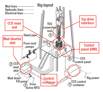
The main CCS elements (Fig. 1) comprise:
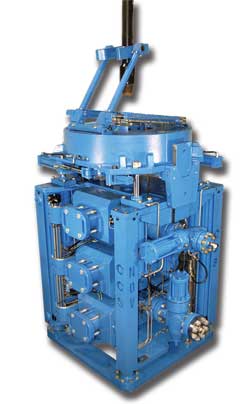
• The Main Unit (Fig. 2) is constructed from three 9-in. bore, 5,000-psi working pressure-rated BOP bodies. Pipe rams are located in the top, blind rams in the center and inverted pipe rams in the bottom. A combination make/break power tong/pipe spinner and vertical snubber is attached to the top of the unit by hydraulic jacks. Hydraulically operated drill pipe slips are attached to the bottom.
• Mud Diverter Unit (MDU), connected to the Bypass Manifold located in the delivery line between the main rig mud pumps and the derrick standpipe. The MDU switches the flow of drilling fluid between the top drive and the CCS during the connection process.
• The Top Drive Interface has three components: 1) Top Drive Extension/Wear Sub (“saver” sub), which is about 8 ft (2.5 m) long. The sub is locked to the bottom of the top drive and reaches inside the Main Unit, to position the connection below the blind rams when drilling or running in. When pulling out with circulation, it picks up the open tool joint box inside the Main Unit; 2) Top Drive Connection Tool (TDCT), suspended below the top drive at the level of the saver sub tool joint, and used to make or break the connection between the saver sub and a stand of drill pipe in the derrick; 3) Dual Sided Elevators (DSE), suspended below the TDCT, and used to pick up and handle drill pipe stands in the derrick. They can be opened on one side to latch around a stand as it is being pulled through the system at rig floor level, and opened on the opposite side by the derrickman to rack or pick up a stand in the derrick.
• Control Panel Human Machine Interface (HMI), located at the driller’s position, through which all system functions are controlled via a touch screen interface.
• Control Container, which contains the system’s Hydraulic Power Unit (HPU) and the “black box recorder,” which gathers and stores data on the system’s operation and provides the Internet data transmission link to the NOV “E-drill” center and 24-hr monitoring of system components.
 |
Fig. 1. Main elements of the CCS system.
|
|
 |
Fig. 2. Main Unit of the system, built from three BOP style bodies.
|
|
Control system. The controls are fully automated, enabling trained technical personnel to safely and efficiently operate the system. It has built-in safety alarms, manual interlocks between activities and reverse or undo steps in the operating procedures. Developing the programming involved reiterative checking of each operating procedure, which resulted in the development of a simulator. As well as designing and testing new operating codes and troubleshooting problems, the simulator is used for training and qualifying new operators for the system.
The operating system is controlled from a touch screen, or HMI. It is self-checking, but it can be interrupted at any stage, and the activity can be reversed by the operator. Most important of all, it is safe for all personnel involved. More details can be found in SPE Paper102851.2
APPLICATIONS
The system has been particularly effective when used to drill formations where there is a narrow-pore pressure/fracture-pressure gradient window, where making connections conventionally can be extremely difficult. If the static mud weight is sufficient to control the well, the additional friction pressure generated when circulating (ECD) is often sufficient to exceed the formation fracture pressure gradient and create losses. Regaining circulation, by reducing the static mud weight and drilling ahead with the ECD, creates problems when circulation is again interrupted to make a connection. The removal of the dynamic pressure component can be sufficient to induce flow and formation collapse, making connections difficult and time-consuming.
Balanced Pressure Drilling is unique among Managed Pressure Drilling (MPD) techniques, because it maintains uninterrupted circulation during connections to establish a constant BHP regime while drilling ahead. This steady state, circulating condition eliminates the transitory downhole pressure effects experienced during conventional drill pipe connections. In HPHT wells, these pressure surges can be significant, causing wellbore ballooning when breaking circulation, and fluid influx and formation collapse when the pumps are stopped. In these conditions, using the CCS results in improved hole conditions, faster total connection times (the elapsed time from stopping to re-starting drilling) and less chance of stuck pipe.
When open annulus returns can no longer be sustained, drilling can continue, using the system in conjunction with rotating BOP equipment and annulus pressure control. With closed hole circulation drilling, the annular chokes are used to supplement the continuous circulation and control minor annular pressure fluctuations created by small influxes, losses or temperature-related changes to mud density. In the event of major losses, drilling progress has been successfully maintained while injecting mud to the drill pipe and maintaining a “mud cap” in the annulus, with the injection of mud if necessary. The continuous movement of fluid keeps the drillstring free in the hole.
Another potential application is high-angle or extended reach drilling, where the potential hazards of high rotary torque and stuck pipe can be minimized by keeping the cuttings moving in the annulus, thereby reducing the build-up of cuttings “weirs” in the deviated hole section.
WELL PLANNING
It is advisable to plan drilling operations in advance, if intending to apply continuous circulation techniques, as all related drilling information must be considered to establish the drilling parameters required. If previous unsuccessful attempts to drill have been made, knowledge of the mud types and densities employed is important, as are pore pressure and fracture pressure data. MWD/LWD/PWD tools can be used with continuous circulation, and should be run to record real-time ECD measurements and other well data as drilling progresses. This allows mud density and circulation rates to be adjusted, as required. On completion of a hole section, the density of the replacement mud and displacement program are needed to allow the drillstring to be pulled. If a liner is to be run, it can be circulated continuously and rotated after the liner hanger and running tool have been made up on the drill pipe.
The CCS can be used on any drilling unit that is big enough to accommodate the Main Unit on the rig floor and is equipped with a top drive. This includes most modern mobile offshore drilling units, platform rigs and most large land rigs. Before starting operations with the system, an inspection team from the service company checks the rig to determine what is required to install and operate the system. Most important are the provision of an electrical power supply, positioning of the HPU, and the layout of the control cables and hydraulic hoses.
The only structural modification required is the installation of mud bypass and MWD filter manifolds in the delivery line between the pumps and the derrick standpipe. This can be done at a time when regular drilling operations will not be interrupted. Since all the mud flow must pass through it before being diverted to either the standpipe or the Main Unit, the filter manifold must be upstream of the bypass manifold. To minimize exposure to personnel, the routing of the high-pressure mud circulation connection between the MDU and the Main Unit on the rig floor must be carefully planned and the hose, or hard pipe, pre-installed, if possible.
The condition and type of top drive is important, as are the number and condition of the main mud pumps. Ideally, there should be three, because two pumps will normally run continuously while drilling with uninterrupted circulation. A flexible mud storage system with sufficient capacity to change out, store and treat the mud volume in the hole is advisable, as well as an efficient treatment system to maintain the required mud density in circulation.
When drilling with continuous circulation, a change in well control practices is required and must be addressed prior to beginning drilling. Balanced Pressure Drilling (BPD) calls for a new approach to well control planning, and it is necessary to re-think the well control procedures to be applied. The reasons for drilling with uninterrupted circulation must be remembered, and dynamic well control procedures must be put in place, with the rig crew trained and prepared to apply them.
If using an underbalanced mud column, circulation must be maintained, and the well must be controlled under dynamic conditions to maintain ECD at the correct level. The normal procedure of stopping circulating, picking up off bottom and closing the BOPs to take pressure build-up readings before increasing the mud weight and circulating out an influx, cannot be done while drilling with continuous circulation. It will lead to the loss of the BPD condition and a return to the loss/flow situation of normal drilling. Against this background, well control procedures specific to the well and the rig employed will need to be prepared and the crews trained in their application.
RECORDS & REPORTING
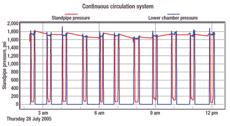
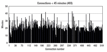
To program the use of a new, innovative system to drill difficult and costly wells, drilling engineers and operations personnel must be confident that the system is designed and operated to deliver the reliability and performance required. To provide this confidence for the CCS, a data gathering and reporting program was developed, for use by both NOV and the oil company’s drilling personnel. The program comprises a Daily Drilling Report, and it includes reports covering each connection made, any issues ensuing, ram seal usage, maintenance record and the spares situation. From these data, graphic reports can be prepared for each stage of each connection sequence (Fig. 3), as well as the standpipe and lower chamber pressures at each stage, Fig. 4.
 |
Fig. 3. A graphic report can be prepared for each stage of each connection sequence.
|
|
 |
Fig. 4. Graphic reports can also be prepared for each stage of the standpipe and lower chamber pressures.
|
|
Separate internal service company reports are not made. One of the aims of this open program was to establish and maintain “jet engine reliability” with the system from the start. This was almost achieved with the first application offshore Egypt and was definitely achieved with the second usage offshore Norway. Supporting the reporting program is the vendor’s E-drill monitoring service run from the Houston technical center. It is manned 24 hr/day and gathers data through an Internet connection to the system’s “black box.” Subject experts can be accessed at any time to consult on equipment malfunctions. In many cases, adjustments to operating programs can be made via the real-time connection. Every effort has been made to ensure the system’s reliability and consistent operation, as well as for its associated equipment.
OPERATIONS
The CCS was first used commercially on the successful re-entry and deepening of the Port Fouad Marine Deep 1 (PDMD1) well in the Mediterranean, offshore Egypt. This exploration well, operated by Eni affiliate Petrobel, had been drilled and suspended above the objective after encountering hole problems related to narrow differences between pore pressure and fracture pressure gradients. Before installation on the Maersk Endurer jackup, the system was tested by Eni on the Pergemine 7 land rig drilling the Monte Enoc 10 well in Val d’Agri field in southern Italy. There, it performed satisfactorily.
PFMD1 was successfully re-entered, and 402 m (1,319 ft) of 8 ½-in. hole were drilled with uninterrupted circulation to 4,991 m (16,375 ft), where a 7-in. liner was run. Rotating BOP equipment was installed, and 5 7⁄8-in. hole was drilled to TD at 5,244 m (17,205 ft), continuously pumping mud to both the drill pipe and the annulus. MWD/LWD/PWD tools recorded formation data and real-time ECD measurements in both hole sections. Re-entering and deepening the PFMD1 well, using continuous circulation, was a great success. The system demonstrated remarkable reliability in its first commercial field application, making 522 connections while drilling and tripping with no interruptions to circulation nor additional rig time attributable to mechanical failure, Fig. 5.
 |
Fig. 5. In its first commercial application, the system made 522 connections while drilling and tripping, with no interruptions to circulation.
|
|
The second commercial CCS was deployed in 2005 on Saipem’s Scarabeo 5 semisubmersible that was drilling for Statoil on the Kristin S-2-H well offshore Norway. The objective was to maintain continuous ECD overbalance while drilling, washing and reaming in an undrilled formation below a depleted reservoir section. With uninterrupted circulation, the ECD was maintained within the required range, and 216 m (709 ft) of 8 ½-in. by 9 7⁄8-in. hole were successfully drilled and under-reamed to TD at 5,362 m (17,592 ft), MD. The system performed reliably throughout, making 151 connections while drilling and reaming, in an average time of 19 min. per connection, with no interruptions to circulation. This more than satisfied the requirements of the drilling engineers. As a result, the CCS is included in the Statoil “tool box” for Managed Pressure Drilling operations.
Details of these operations can be found in SPE Paper 1028593.
SAFETY
The CCS has been designed with a clear emphasis on safety, principally for the personnel involved, but also for the well being drilled. Drilling with the system does not involve any changes to the drillstring. No additional components or connections are required. It is exactly as for normal drilling. No drillstring leaks, or attributable damage, have been recorded during drilling with the system. All connection operations—making up or breaking out tool joints at circulating pressure—take place within the Main Unit.
The Main Unit is constructed from tried and proven blowout preventer components and is regularly tested. The ram seals, which are subject to wear from the drill pipe moving through them while pressurized, are easily changed during the time between connections while drilling continues with the Main Unit in place. The operation of making and breaking connections while continuously circulating does not require manual intervention. The process is controlled from the HMI touch screen, and members of the rig crew are isolated from the Main Unit and ancillaries, and are protected from any possibility of injury.
CONCLUSION
The CCS has proven to be a safe, reliable system that allows operators to successfully drill HPHT wells and wells with narrow pore pressure/fracture pressure gradient windows that were previously difficult to drill, time-consuming and expensive. It can also be used with Closed Hole Circulation Drilling to drill reservoirs, where formation damage and impaired production can be reduced, maintaining continuous circulation and controlling the ECD overbalance. The system has proven to be safe and reliable to operate, and has successfully achieved its programed drilling objectives.
LITERATURE CITED
1 BG, BP, Eni E&P, Shell UK, Statoil and Total.
2 Calderoni, A., et al, �The Continuous Circulation System�From prototype to commercial tool,� SPE paper 102851, presented at the SPE Annual Technical Conference and Exhibition, San Antonio, September 2006.
3 Calderoni, A., et al, �Balanced pressure drilling with continuous circulation using jointed drill pipe, etc.,� SPE paper 102859, presented at the SPE Annual Technical Conference and Exhibition, San Antonio, September 2006.
|
THE AUTHORS
|
|
Rod Vogel is director, Global Rental Operations, for National Oilwell Varco. He began his career with Marathon in the US, where he held various positions in reservoir, operations and drilling. In 1993, he left Marathon to found a horizontal drilling company specializing in short-radius horizontal and underbalanced drilling. Mr. Vogel joined Weatherford in 1997 and held several international positions managing underbalanced drilling operations and projects. He joined National Oilwell Varco in 2003. Mr. Vogel holds a BS degree in petroleum engineering from Penn State University and an MBA degree from the University of Texas.
|
|
| |
Jim Brugman is chief engineer of National Oilwell Varco's Pressure Control Group in Houston. He has led the new product development efforts for this group (formerly the Shaffer division of Varco International) since January 1994, and has been responsible for new product R&D engineering since that time. Prior to that, he spent 21 years developing new products for Varco Oil Tools and Varco Drilling Systems in Orange, California, where he was responsible for the development of the Iron Roughneck, Top Drive Drilling System, Pipe Handling Machine (PHM), Star Racker and the Pipe Transfer System. He received a BSE degree in Mechanics and Structures from UCLA in 1975.
|
|
|


