Intelligent Well Completions
Multi-zone, multi-sensor intelligent WAG injector
Offshore Norway well uses optical flowmeters and downhole flow control valves.
Espen S. Johansen, Weatherford
 |
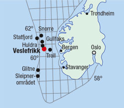
Fig.1. Statoil’s Veslefrikk platform is in block 30/3 in the Norwegian North Sea.
|
|
In May 2004, Statoil installed a Water Alternating Gas (WAG) injector in well 30/3 A-11 B on the Veslefrikk platform in the Norwegian North Sea, Fig. 1. The intelligent completion covers four formations: Ness 2, Etive, Oseberg 2, and the Intra Dunlin Sands (IDS). It includes two 3-1/2-in. and one 4-1/2-in. optical, single-phase, flowmeters set at 2,561, 3,138, and 3,340 m.
To control the zones’ injection rates, the completion uses three variable downhole inflow control valves (ICV) and one on/off valve. The well’s injection rates reached 40,000 bpd of water and 60 MMcfpd of gas during maximum injection.
The optical monitoring equipment and valves are functioning well after nearly two years of water and gas injection. For Statoil, the equipment combination allows reservoir pressure management and production optimization by monitoring and controlling injection rates for each zone. The company estimates that the Downhole Instrumentation and Control System (DIACS) will account for half of the well’s value creation over the well’s life.
VESLEFRIKK FIELD
The Veslefrikk field is in the North Sea on Norwegian block 30/3 and is developed as a combination platform and floating production facility. The fixed wellhead platform has 24 slots with estimated recoverable reserves of 226 million bbl. The field began production in 1989 and was expected to produce that oil over a 20-yr span. To date, it has produced 283 million bbl with another 63 million bbl remaining.
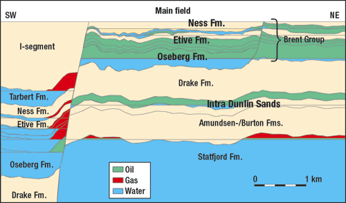
Each reservoir has a different fluid system. The Ness 2, Etive, Oseberg 2 reservoirs of the Brent Group have pressure regimes independent of the IDS, Fig. 2. Most of the wells commingle production.
 |
Fig. 2. Each reservoir has a different fluid system and the Brent Group reservoirs have pressure regimes independent of the Intra Dunlin Sand.
|
|
Seawater injection supports pressure in the Brent Group. WAG injection reduces residual oil saturation in the field’s water-flooded areas. Statoil recently change the field’s injection strategy. The Statfjord formation is on gas recycling and will be converted to WAG, which will allow the Brent Group to receive more WAG. IDS has been using WAG for several years.
One of the field’s challenges is opening well slots for new infill or multilateral wells. By installing DIACS completions, injectors will become more efficient and need fewer slots. This will open more slots for producing wells.
COMPLETION DESIGN
An intelligent completion is needed to direct water and gas injection selectively into different zones and to monitor injection rates. It needed to close zones where gas injection was not helpful and choke back zones that drew too much water. Additionally, Statoil wanted to monitor and remotely control sleeves and sensors from onshore. Production engineers also needed the flow and pressure/ temperature (P/T) data to be easily accessible.
 |
Fig.3. The downhole instrumentation and control system allows reservoir pressure management and production optimization for each zone.
|
|
Reservoir temperature was a major challenge. Equipment needed to operate at 125°C during shut-in with rapid temperature drops to 15 – 30°C during water injection. Another challenge was to find flowmeters that could measure water and gas flow rates over a wide range without hardware changes. The monitoring equipment selected for Veslefrikk was Weatherford’s optical single-phase flowmeter with integrated optical pressure and temperature sensors. Three flowmeters were placed between the four zones to monitor the flow rate to each of the zones. Zonal flow rates are determined by differencing.
The flowmeters are connected to surface instrumentation with a single fiber optic cable requiring only one wellhead penetration. The optical cable has three single-mode fibers. Each pair of flowmeter and P/T gauges share one fiber and are interrogated using wavelength division multiplexing. The P/T gauges are located optically below each flow meter.
For Veslefrikk, three 3-1/2-in. direct, hydraulic-control, variable valves and one 5-1/2-in. on/off valve control downhole flow into each of the four zones. The ICVs employ four hydraulic closing lines and one common opening line. The valves produce a small pressure differential in their fully open position.
The completion equipment includes: a 10,000-lb christmas tree, a seven feed-through tubing hanger, a five feed-through tubing head, 5-1/2-in. slim-design downhole safety valve, one 5-1/2-in. on/off direct hydraulic control valve, three 3-1/2-in. direct hydraulic variable control valves, three 3-1/2-in. optical flowmeters, three annulus optical pressure and temperature gauges, three tubing strings (5-1/2-in., 20-lb; 5-1/2-in., 23-lb; and 4-1/2-in. 12.6-lb) and a 7-in., 29-lb liner, Fig. 3.
OPTICAL FLOWMETERS
The optical flowmeter can measure liquids and gasses without changing the flowmeter hardware or software. The tool has no intrusions and no exposed sensors, it produces no permanent pressure loss and resists erosion. The meter has no downhole electronics, no moving parts, and no nuclear sources, so crews can workover, perforate, or hydraulically fracture with the flowmeter in place. The device is rated to 160°C with a maximum pressure rating of 1,000 bar and can be configured as single-phase or as a multiphase flow measurement system.
The meters use dynamic pressure sensors to measure turbulent flow pressures, Fig. 4. The sensors track the propagation of eddies as they convect through the pipe. In single-phase flow, this system has shown accuracy of ±1%. The flowmeter is bi-directional and gives both flow rate and direction. This feature is useful during shut-ins, where inter-zonal cross-flow has been observed.
 |
Fig.4. Flowmeters use a dynamic pressure sensor to correlate turbulent flow pressures with the fluid convection velocity in the pipe.
|
|
INSTALLATION
Beside well control and contingency procedures, the focus during installation was on reducing the length of assemblies.
With overbalance mud in the tubing, 46 m of the well was perforated using 4-1/2-in. TCP guns. A clean-up run removed debris, while drifting the liner and casing. Then, a kill pill covered the perforations and completion fluid was circulated.
Pre-made valve and flow meter assemblies of varied in length from 8.0 m to 15.6 m. Dedicated tubing joints were installed in the completion string for space-out and fiber optical cable was pre adjusted to fit between each zone. After a function test, the control lines were attached. After running 3,400 m, engineers used a wireline casing collar locator/ gamma ray tool to locate the completion string position.
The seven control lines were threaded through the tubing hanger and the completion string was landed. After displacing with packer fluid, a production packer was set and the three isolation packers were pressurized. Lastly, the control lines were connected to surface control system.
COMMISSIONING
Statoil’s installation represents a number of “world’s first” for optical flowmeters: first intelligent well, first flowmeter integrated with ICVs, and first high-rate WAG injector.
During commissioning, at low to moderate injection rates all the flowmeters functioned properly. While the P/T sensors were fully functional at all injection rates, with increasing injection rates flowmeter functionality was lost. The non-functioning flowmeters were examined and their optical integrity was verified.
Using a structured step-rate test program, engineers determined that the flowmeters lost functionality due to high acoustic-noise generated by the ICVs. High velocity fluid was generating noise by exiting the ICV radially and hitting the casing. This observation led to a re-design of the optical demodulation software.
These problems were not observed in producing wells in the past. With the upgraded software, the system can now tolerate extremely high acoustic noise levels.
MEASURED DATA
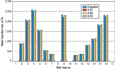
There is excellent agreement between downhole measured rates and surface injection rates, The deepest zone, IDS, was step-rate tested. The four flowmeters show very little deviation from the surface flowmeter, Fig. 5.
 |
Fig.5. The Intra Dunkin Sands were step-rate tested with the four flowmeters showing agreement between downhole measured rates and surface injection rates.
|
|
Veslefrikk A11-B requires limited water injection into zone 2 coupled with gas injection for optimal reservoir management. Water injection is done through zones 1, 3, and 4. The well injected over 10 million barrels of water between June 21, 2004, when injection began, and May 30, 2005. The development strategy for individual reservoirs can be refined from the well’s online accessible data.
CONCLUSION
Statoil can now manage its reservoirs better, since it has real-time access to pressures, temperatures, and injection rates for each of the zones. The real-time flow rates are integrated to calculate total injection volumes for each of the zones. Downhole flow control allows for selective zonal tracer injection. The online pressure sensors are also used to verify downhole zonal isolation and flow control integrity.
Without this intelligent completion, a frequent and costly wireline-logging program along with at least one additional $10 million well would be needed to gain the present reservoir management. Using a multi-zone injector saved 1-2 well slots that are now available for a producing well. 
REFERENCES
B. Sandøy,; T. Tjomsland,; D. T. Barton, G. H. Daae, E. S. Johansen,; G. Vold; Improved Reservoir Management with Intelligent Multi-Zone WAG Injectors and Downhole Optical Flow Monitoring, SPE 95843 presented at SPE Annual Conference, Dallas, Texas, USA., October 9 – 12, 2005.
|
THE AUTHOR
|
 |
Dr. Espen S. Johansen is the global product line manager for optical flow measurement at Weatherford International Ltd. Johansen has been with Weatherford for four years. He holds a Ph.D. in Aerospace Engineering from Texas A&M University, where NASA and the Air Force Office of Scientific Research funded his research on unsteady aerodynamics.
|
|
|


