|
Vol. 227 No. 1 |
| |
 |
TSBR, an alternative solution to bundled hybrid riser designs
Top sliding bundle riser eliminates submarine flexible risers for HP/HT offshore wells.
Pierrick Sauvage, Remy Menu, and Benjamin Rousse, DORIS Engineering, Paris
Doris Engineering pioneered the design and realization of riser towers at the end of the 1970s with the Cosmos Project for the Commissariat a l’Energie Atomique. The concept of bundled hybrid risers (BHR) was then derived in the Gulf of Mexico (1988 and 1992) for deepwater offshore applications in West Africa’s benign environment. This led to the installation of three riser towers on Angola’s Girassol field offshore.
Since then, the company has conducted a study for the French Ministry of Industry on the applicability of hybrid riser towers to HP/HT environments. This study, funded by the Comite d’Etudes Petrolieres et Marines (CEPM) was initiated in 2004 and is being detailed in 2005 with the support of FMC.
DESIGN OUTLINE/ ELEMENTS
The Top Sliding Bundle Riser (TSBR) is a bundled riser with a flexible joint at the bottom and a vertically-sliding, pinned connection along the Floating Production Unit (FPU) riser porch, Fig. 1. The tower is composed of six parts, from bottom to top:
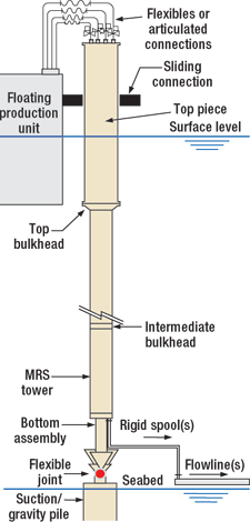 |
Fig. 1. The TBSR has six parts: suction anchor, flexible joint, bottom assembly, rigid spools, main riser section top piece and spools.
|
|
- Suction pile anchor
- Flexible joint
- Bottom Assembly (BA)
- Rigid spools at the tower foot to the flowlines
- Main Riser Section (MRS)
- Top Piece (TP) from the top of the MRS up to the top spools, guiding the TSBR to the FPU side
- Spools from the MRS to FPU top flanges.
Anchor. A suction pile anchor holds the tower in place at the seabed. The typical range for uplift force to resist the suction pile is 1 to 5 million Newtons (MN): 5 MN maximum if all risers are empty, 2 MN in normal operations, and 1 MN as a minimum. The design’s vertical up-tension is smaller than that for standard BHRs, since the buoyancy foam only needs to be adjusted for tension control (there is no buoyancy tank with redundant flotation).
Depending upon the lifting capabilities of installation spreads and soil data, the suction pile holding capacity can be supplemented with additional, separately installed gravity weights on the pile’s top.
Flexible joint. Due to the environmental loads and FPU motion, it is necessary to allow rotational motions of the tower around its anchored point. A flexible joint located between the tower and the anchor permits this, while maintaining the axial load connection to the seabed.
The movements at the top of the tower follow the excursions of the FPU, a maximum 5 – 8% of the water depth. The behavior of the MRS is similar to Girassol’s tower (similar diameter, mass and stiffness). Therefore, the movements at the tower’s bottom are similar and the same flex-joint system is applicable. During the installation phases, the flex-joint accommodates about 10° inclination for TSBR parking during FPU mooring.
Bottom assembly. The BA fulfills several functional requirements, Fig. 2. Using a transition piece, it transfers loads from the MRS current section to the foundation. It guides the risers at the bottom of the TSBR at the end of the MRS (upper guide support) and supports the connector tools for installation of the spools (lower guide frame). The BA protects the riser ends behind the guide frames during tow and provides flotation of the TSBR’s end for surface tow with a buoyancy module (this can be removed before upending or left in place).
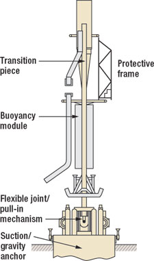 |
Fig. 2. The bottom assembly provides anchoring and guidance at the bottom of the TSBR for pulling down and docking of the bundled hybrid riser in the foundation.
|
|
The BA provides anchoring and guidance at the bottom of the TSBR for pulling down and docking the BHR in the foundation. Lastly, it allows landing and jacking-up of the spools prior to transfer to the riser/ spool connectors.
Rigid spools. Rigid spools connect the bottom of the risers to the flowlines. The spools compensate for rotations of the BHR at the bottom and allow the elongation and displacements that are induced at the end of the flowlines from Poisson and thermal effects. For the rigid spools connections, vertical collet connectors or flanged connections can be adapted. The bottom spools can be installed after the MRS locking and prior to TP/FPU arrival, avoiding the schedule’s critical path.
Main riser section. The MRS extends from the bottom assembly to the transition piece at about 15 m under the water’s surface. The MRS, Fig. 3, is made of a buoyancy foam matrix, risers, core pipe forming the structural back-bone (typical 20-in. diameter, 1-in. thick, air-filled steel pipe), and bulkheads at the top and at intermediate sections. The riser bundle typically includes: one 16-in. oil export line, one 6-in. gas import/ export line, two insulated Pipe-In-Pipe (PIP) production lines formed of one 8-in. pipe inside one 12-in. pipe, two 10-in. water/ gas injection lines, and/or two 3-in. gaslift lines. The outer diameter of the bundle riser is 1.5 to 2 m.
 |
Fig. 3. The main riser section is made of buoyancy foam, risers, core pipe and bulkheads.
|
|
The buoyancy foam matrix is made of syntactic buoyancy blocks 5 to 6 m long, rated for the design water depth with a foam density of 400-450 kg/m3. The blocks are interlocked, strapped and supported along the MRS risers or/and the core pipe via collars at regular 5 – 6 m spacing. The blocks, surrounded by seawater, will be subject to moderate temperatures from the risers (water and/or gas injection maximum design temperatures). The outer pipe of the PIP system is not warm.
The top bulkhead is crowned by the risers’ terminations with blind flanges for connection to the TP’s top risers. A steel frame protects the flanges to allow guidance and protection from the guided pins of the TP during its lowering and connection to the MRS.
Top piece. Fixed at the top of the main part of the tower, the 20 – 40 m TP makes the sliding pin connection between the FPU ring and the MRS, Fig. 4. It guides the top risers from the MRS to the FPU, accommodating the safety valves at the top. It must be neutrally buoyant to avoid compression in the top of the MRS. In order to ease the upending of the MRS and the hook-up to the riser base on site, the TP is installed once the MRS is in place.
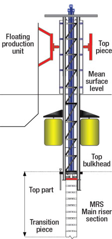 |
Fig. 4. The top piece makes the sliding pin connection between the FPU ring and the MRS.
|
|
The TP is a steel-framed structure with permanent buoyancy. The buoyancy can be syntactic foam or steel cans. Steel cans are used to control the uplift with partial water flooding during different life stages. The frame is circled by disposable wearing sleeves along the path of the connecting ring roller bearings.
The rigid risers are pre-installed in a pattern in the TP guide frame. Quick-lock connectors are used to secure the MRS top ends of the risers. Then, flexible or articulated steel jumpers are connected from the top of the TP to the FPU.
The framed TP allows for diver inspection and intervention atop of the MRS and minimizes steel weights and buoyancy. The design reduces waves and current forces and the sliding FPU connection is a more flexible geometry.
The TP is floated and lowered to the MRS top. Its floatation is designed to keep the TP stable at this interim stage during the lowering and to its fastening to the MRS. The connection mechanism is made of vertical pins of adjusted heights for guidance and four grouted piles for permanent load transfer. The lowering and temporary fastening prior to grouting is done by four tensioning slings and a winch system located at the top working platform of the TP.
The connecting ring is based on a sliding ball joint principle and is similar to the keel joints used for spars. The connection is characterized by moderate load transfer (100 t max), small working angles (+/ – 10°) and a limited vertical maximum sliding course.
The connection system is split into two pieces that allow connection to the FPU, once the tower is in place. Later, it permits inspection and replacement of the wearing sleeve and of the sliding mechanical components. The advantage of the sliding ball joint system is to center the load transfer, minimize the friction and avoid the blocking of the sliding tube.
Circular access at the top of the ring permits intervention, maintenance and replacement of the track bearings from a working platform. At the bottom of the ring, a protection frame allows for temporary guidance of the TP cylinder and avoids damage of the TP on the roller bearings prior to installation. If required, temporary shock absorbers can be installed between the protection frame and the TP cylinder during the offshore connection.
Spools. Spools connect the risers at the top of the tower to the FPU. First, steel risers are connected from the MRS bulkhead to the top platform of the TP. These are capped with an emergency shut down valve operated from the TP platform. Then the spools, hanging from the FPU, complete the riser connections to the flanges above the TP platform.
The steel risers are guided in the TP riser frame, are lowered, and then connected in place with quick lock connectors after TP/MRS installation. The spools accommodate the relative movements between the FPU and the TSBR.
Standard flexibles are proposed as a base case for all the risers’ spools. These are supported from the FPU riser hanging platform on the side of the topside module. Each is hung by a standard riser tensioning system (cables, sheaves and counterweights). The system accommodates relative motions and avoids extra vertical weight loads on the top of the TSBR.
For the high temperature production lines, a specific combination of high-design, inner fluid temperature and pressure occur during initial production stages. For these spools, dedicated pantograph articulated risers are chosen.
To allow pigging of the production loop, 8-in. temporary flexibles may be installed, in addition to the articulated riser spools, via a T-connection above the TP platform. These lines can also be used in lieu of the pantograph, once the inner fluid temperature ranges have dropped below the allowable operating values.
BUOYANCY TANK
For current BHRs, the most critical design aspect is in the Buoyancy Tank (BT) to MRS connection, particularly during tow. Up to half of the fatigue life is used during these temporary conditions. Thanks to the BT tension, the core pipe is subject to limited compression. In return, the amount of MRS buoyancy is governed by the tow and the BT provides the uplift force to carry the weight of the inner fluids in the risers and part of the jumper loads.
Since the MRS is towed and upended alone, before being connected to the TP, the top connection for the TSBR must follow the horizontal motions of the FPU.
DYNAMIC BEHAVIOR
Conceptual dynamic analysis estimated the dynamic behavior of the TSBR along its full height, and then derived the stress distribution of the riser tower for ultimate and fatigue limit states. Caladyne/ ADYF3D software was use for the analysis of the TSBR coupled to Diodore for the hydrodynamic analysis of the FPU and for a non-linear spectral analysis in place of time domain simulations.
For the MRS, the core pipe is modeled with its attached buoyancy and equivalent risers are added in both directions, laterally restrained with sliding guides at quad joints spacing. Intermediate bulkheads are included.
The BA is modeled as a structural beam linked by a flexible joint element with equivalent stiffness at ground level. The TP is modeled as an equivalent cylinder with adapted mass, inertia and buoyancy properties.
Modal analysis derived the 2 x 3 first modes for 89-, 44- and 29-second periods, which represents an 85% cumulated modal participation, Fig. 5.
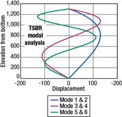 |
Fig. 5. Modal analysis derived the 2 x 3 first modes for 89-, 44- and 29-sec periods.
|
|
The spectral dynamic analysis allows coupling the full motion response of the FPU to the top connection of the tower with the environmental loadings applied along the TSBR body. The TSBR exhibits moderate displacements under max FPU offset and 100-yr conditions are moderate, Fig. 6.
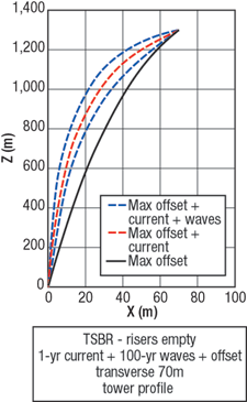 |
Fig. 6. The TSBR exhibits moderate displacements under max FPU offset and 100-yr conditions.
|
|
STRUCTURAL DESIGN
The key issues for the TSBR design included: components resistance to HP/HT conditions, the upper connection design for extreme and fatigue, the transition zone design (top of MRS), and compression reduction in the core pipe.
HP/HT conditions occur along the production risers’ path. At the bottom, the rigid spools are insulated according to flow assurance requirements with temperature resistant materials. Along the current section of the MRS, PIP is used. Above the TP, off-the-shelf solutions can be adapted for valves and risers, such as double pantograph systems with swivel joints.
The MRS section is always in tension to maintain the equilibrium of the tower. However, during limited phases of riser water-filling for hydrotest or at the end of production stages with high water cuts and degraded buoyancy properties, the MRS submerged weight increases and reduces the overall tension, such that core pipe compression might occur. This is exacerbated when the buoyancy is attached along the core pipe using stop collars at regular intervals. For the TSBR application, all the tension is derived from continuous buoyancy and not by the BT at the top of the BHR.
On standard BHRs, the compression can be cancelled by increasing the top tension through enlargement of the BT. This solution is not cost effective. An alternative is to remove the stop collars and design the buoyancy foam as sliding blocks up to the top bulkhead. But, as the foam column is now in compression, it will induce lateral buckling loads.
Finally, the load path can be optimized by implementing bulkheads at key elevations; at a minimum two are required, one at the top and the second near the bottom of the MRS. The longitudinal loads are then distributed pro inertia between the core pipe and the risers, Fig. 7.
 |
Fig. 7. The ultimate normalized combined stress (effective tension plus bending moment) in the core pipe can occur during limited phases of riser water-filling or at the end of production stages.
|
|
The critical locations are the transition pieces between the MRS sub-assembly sections, particularly at the upper transition zone under the TP. For the remaining sections, thanks to the flexibility of the riser tower, the bending of the MRS allows it to safely carrying the wave and current lateral loads by longitudinal loads in the core pipe, which acts as a curved backbone. The core pipe diameter/ thickness is increased in the first quad joint, as are the risers, to ensure smooth attenuation of the bending loads in the longitudinal pipes.
The size, quantity and arrangement of the bearings is critical. An estimate of the contact load distribution through the service life is required for PU track bearing sizing. Pre-tension is calibrated to maintain bearing contact for the TP under 100-yr extreme conditions with a contact load range of 0 – 0.6 MN per bearing, with 0.3 MN as the static pre-stress load.
INSTALLATION
The TSBR can be installed prior to FPU arrival with minimum hook-up time after FPU arrival prior first oil. The installation sequence includes:
- Build and install the suction pile and the receiving part of the flexible joint
- Build the MRS current section onshore
- Tow the MRS is to the site; the tower is designed to have a net buoyancy of 50 – 80 kg/m
- Upend and connect the MRS to the suction anchor via the flex-joint
- Install and connect the bottom rigid spools to the flowlines
- Install the TP on top of the MRS.
Once installed, The TSBR can be parked onsite, while the FPU is being installed onsite.
Once the FPU is towed to the site, the TSBR is connected. With the FPU mooring onsite, the connecting ring (ring opening, installation of temporary shock absorbers, cables and fastening lines to half of connecting ring) and other installation aids are prepared. Next, the TP is pulled inside the connecting ring and secured, Fig. 8. The top spools are connected, so that final hydrotesting and commissioning can occur.
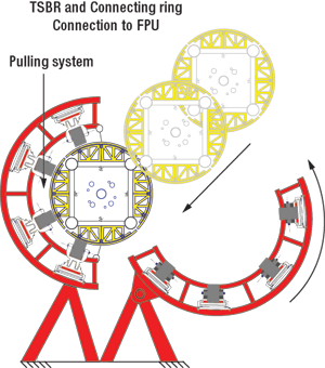 |
Fig. 8. With the FPU moored onsite, the TP is pulled inside the connecting ring and secured.
|
|
CONCLUSION
The TSBR is an alternate solution to BHR designs adapted to HP/HT. The TSBR is an attractive alternative and an improvement to other riser concepts, because it eliminates the need for costly and technically challenging submarine flexibles with high temperature and pressure requirements. The design allows for easy access from the FPU to riser tops for valve operations, riser isolation and for coil tubing interventions.
The TSBR minimizes load impacts on the FPU for hull sizing and mooring design, since there is no vertical tension and minimum horizontal loads compared to flexibles or steel catenary risers. The TSBR can also be disconnected from the FPU for maintenance or intervention.
Future work continues on connection piece validation with fatigue and ultimate excursion resistance for FPUs. Additional work will further adapt the pieces for variable draft floaters such as FPSOs. The MRS section will be further optimized to reduce buoyancy requirements, seeking to remove the core pipe in mid-subsections and optimize the structural participation of risers. This will lead to setting the water depths limits for the concept. 
ACKNOWLEDGEMENT
This article is derived from OTC-17315-PP, which was presentation at the 2005 Offshore Technology Conference held in Houston, TX, U.S.A., May 2 – 5, 2005 and is reprinted with permission.
REFERENCES
1 F. Thiebaud, V. Alliot and S. Hatton, “A cost effective concept for deepwater insulated flowlines and risers,” DOT 1998, New Orleans, 1998.
2 F. Thiébaud, S. Luteyn and D. Perinet; “Design Drivers of Hybrid Riser Tower,” Draft for OMAE 2005.
3 Rapport, “Tour Riser Pour Fluide HP/HT,” M.7556/02, Comite d’Etudes Petrolieres et Marines.
4 J. L. Legras, S. Hatton, “Restrained Hybrid Buoyant Riser Tower for Deepwater Developments,” DOT 1999.
THE AUTHORS
|
| |
Pierrick Sauvage is a field development manager and has 15 years with Doris Engineering involving deepwater flowlines and riser applications for West Africa’s offshore. Sauvage earned a chartered engineer degree in mechanical construction, shipbuilding hydrodynamics and offshore engineering from E.N.S.M. D.E.A. with emphasis in fluid mechanics and thermal transfers.
|
|
|
Remy Menu earned a marine engineer degree from the Engineering Institute of Science in Toulon ISITV and has specialized in deepwater technology in the SURF department for Doris Engineering. Menu is currently involved on the riser tower design verification on behalf of Doris Engineering for the ROSA D/E field development project.
|
|
|
Benjamin Rousse is a riser engineer for Doris Engineering specializing in riser design for West African deepwater projects.
|
|
|
|


