Coiled Tubing Technology
Coiled tubing drilling improves oil recovery in Gannet field, North Sea
Dynamic Annulus Pressure Controlled (DAPC) drilling develops stranded reserves.
A. Laird, Leading Edge Advantage, Ltd., K. McFadzean, Leading Edge Advantage, Ltd., J. Edgar and
I. Harty, Shell Exploration and Production
Infill targets have regularly been identified in the North Sea’s offshore fields and novel techniques have been
implemented to access these targets. Due to the small reserves volume of the targets, engineers need inexpensive drilling options to economically access these stranded
reserves.
Unique logistical and drilling complexities, combined with the limited number of candidates on each platform, have
generally hampered any prolonged campaign of wells. These, in conjunction with the shakedown problems and learning curve associated with implementing different
technologies and teams of personnel, result in limited success for both Through Tubing Rotary Drilling (TTRD) and Coiled Tubing Drilling (CTD). TTRD has become the
primary candidate for slimhole drilling, however, there are circumstances where CTD provides clear benefits.
Drilling into depleted mature fields has a number of risks, primarily, the compromise between maintaining borehole
stability and minimizing overbalance while drilling. The majority of North Sea wells have suffered by compromising differential sticking and wellbore stability, and many
have experienced early termination from these drilling hazards.
Dynamic Annulus Pressure Control (DAPC), or managed pressure drilling, provides a solution for minimizing the risks. If
proven successful, it provides a solution for many stranded targets.
The Gannet ‘A’ field offered significant scope for sidetrack drilling. Five of the initial oil producers are
watered-out, and more are expected to water-out in the coming few years. Learning from the first few sidetracks would make the drilling of future sidetracks easier. In
addition, wells in the central part of the field offered the possibility for a second sidetracking campaign, because there is a shrinking gas cap and continuous upward
movement of the remaining oil rim.
THE CHALLENGE
The Gannet “A” wells were drilled and completed horizontally in the middle of the oil rim. The positioning aimed
to maximize production by minimizing gas and water coning during production. Due to excess gas production throughout the field life, the oil rim migrated into the
original gas cap location, eroding the accessible reserves. The oil movement led to water migration, watering-out the wells in the northern part of the field.
The strong water drive, coupled with a lack of reservoir pressure seals minimized pressure depletion across the formation.
The reservoir pressure has only dropped 300 psi from the original 3,250 psi to 2,950 psi. Using a 200 psi pressure margin over pore pressure results in an effective mud
weight of 435 pounds per thousand foot (pptf).
Purely increasing the production from the existing wellbores would increase water and gas coning and be detrimental to oil
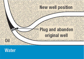
production. Therefore, the team proposed exiting the existing wells at the heel in the reservoir section to target the stranded reserves at the top of the sand, Fig. 1.
 |
|
Fig. 1. The team proposed exiting the existing wells at the heel in the reservoir section
to target the stranded reserves at the top of the sand. |
|
Drilling options. The original Gannet wells were drilled in tender assist mode using the Sedco 704
semisubmersible, which provided the power generation and drilling fluid system. The derrick equipment set consisted of: a derrick and sub-base with 500 bbl mud tank,
draw-works and top-drive, BOPs and other pressure control equipment and other miscellaneous drilling sub-systems.
When the vessel departed in 1997, the topdrive was removed and the remainder of the drilling package was mothballed. This
meant that any infill drilling would require either reinstatement of the original drilling facilities, or an alternative approach.
An investigation of how the targets could be reached was performed in 2001 and 20044,5. The options and
relative costs are presented in Table 1. The only two options that were technically and economically viable were options 6, a temporary rig, and 7, CTD. Of these two, CTD
was the most attractive.
| TABLE 1. Cost comparison for the different
drilling techniques |
 |
|
STUDIES AND DESIGN
The basis of design and the drilling program outline were developed, based on CTD, and the project team assembled. The
core team for the project consisted of: project manager, project/ operations engineer and two lifecycle well engineers, with support from the asset and subsurface
departments. The team split the work into three sections:
- Project: contracts, safety case review and resubmission, risk assessments, peer reviews, trials, personnel, training
- Surface: platform reviews and modifications, change process review and implementation, integration with platform safety processes (e.g.
fire and gas), temporary equipment requirements and new build equipment, logistics
- Subsurface: upfront well preparation, targets, detailed well design and drilling program, equipment procurement.
A long time was spent in setting up the main CTD contract, which had an effect on the other project services. A
substantial amount of work was performed prior to in-depth supplier involvement, leading to a reduction in the project input. Future projects would benefit because the
contract process is completed prior to concept selection, thereby ensuring that the suppliers are involved more in the detailed design phase.
Wellbore stability. The Tay sand section is divided into discrete units by shale horizons. The target for the
sidetrack was to reach a depth as high in the reservoir as possible. From the highest exit position, this still required the well to climb from the casing exit to TD and
required the wellbore to pass through the shales between the sand units D and E. A stability study from an offset well determined that a 570 pptf equivalent mud weight
was required for borehole stability, compared to the 435 pptf needed for well control.
Wellbore restrictions. The original wells were drilled with the 9-5/8-in. casing landed into the top of the Tay
reservoir. Some of the wells, including GA-03, had long tangent sections at 55° – 60° inclination from approximately 3,000 ft to the top of the reservoir
at 11,000 ft along-hole-depth (AHD). This, along with a lack of rotation, compounded hole cleaning.
The 4-1/2-in. x 5-1/2-in. completion in the wells and the associated jewelry resulted in a number of 3.313-in. and
3.250-in.restrictions. The team assessed the restrictions and decided that these would be milled out to 3.4 in. The maximum size was related to the size of the side
pocket mandrel at 8,643 ft AHD.
All restrictions, including the 11.5 ft wireline entry guide, were milled ahead of mobilizing the CTD spread. This ensured
that the work was performed offline with a cheaper equipment spread, so that any difficulties could be handled with a low dayrate and a larger window of opportunity,
reducing time and cost.
ECD effects. Milling the completion restrictions to 3.4 in. meant that the openhole could be drilled using a
concentric 3-3/8-in. bit or enlarged using a bi-center bit. A concentric bit was selected, since this was the first well to be drilled in this formation using CTD and due
to the large dogleg severity required to reach the target horizon without entering the water leg.
A comparison was performed using two different mud weights. The first system was designed at 435 pptf, satisfying the 200
psi overbalance criteria required for conventional drilling. The second mud system was designed at 570 pptf for borehole stability.
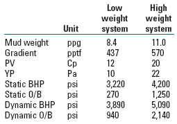
The mud weight required for borehole stability results in a static overbalance of 1,250 psi, Table 2. Pumping this fluid
at the rates required for hole cleaning increases this value to a dynamic overbalance of over 2,000 psi. Historically, CTD wells drilled with overbalances of more than
1,500 psi have experienced differential sticking and hole loss.
| TABLE 2. Mud weight modelling comparison |
 |
|
To avoid this, a number of methods were investigated to reduce the effective circulating density (ECD). The paper by Kara
et al.1 described a potential solution. The team desired an automatic, rather than a manual, system.
DAPC system. During the feasibility phase of the project, the Shell R&D facility at Rijswijk, The Netherlands,
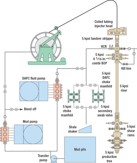
was developing an automated system for controlling the surface back pressure, while drilling, to maintain a constant BHP. The DAPC system consists of three main
components, Figure 2: an electric automated high-pressure fluid pump, an automated choke manifold and a computer control system.
 |
|
Fig. 2. The DAPC consists of an electric automated high-pressure fluid pump, an automated
choke manifold and a computer control system. |
|
An automated choke is run in parallel to a conventional well-control choke manifold to control the wellhead pressure (WHP)
during the operation. This is controlled by a process logic control system that automatically adjusts the pressure at the choke depending on mud properties, flowrates,
and the BHA depth. To maintain optimum flow through the choke, an additional dedicated pump boosts the flow through the choke whenever the flow at surface is reduced
below 42 gpm.
The system uses a hydraulics modeling program, EzClean, to determine the system pressures while circulating and alters the
surface pressure to accommodate for system pressure losses by monitoring wellhead pressure (WHP), circulating pressure, choke setting, CT depth and amount at surface, mud
parameters, flowrate in and out, and real-time BHA pressure while drilling.
When the well is being circulated using the mud pumps, the system adjusts for friction pressure by controlling the choke
position. If the rig pumps are stopped, the system recognizes the flow reduction and the pump automatically kicks-in. This increases the fluid flowing across the choke
manifold and maintains the choke in the optimum operating range to ensure accurate WHP is maintained.
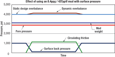
Fig. 3 shows the advantage of using DAPC to minimize BHP while drilling. The static mud weight was designed to be 200 psi
over the pore pressure to provide adequate well control. To provide sufficient stability to the shales while drilling, a backpressure of 950 psi was imposed while the
well was static. This provided an equivalent BHP of 570 pptf.
 |
|
Fig. 3. When circulating, the wellhead pressure is reduced by a pressure equivalent to
the dynamic annular frictional pressure. When circulating is stopped or reduced, the reverse occurs. |
|
When circulating, to ensure that the BHP remains the same, the WHP is reduced by a pressure equivalent to the dynamic
annular frictional pressure. When circulating is stopped or reduced, the reverse occurs, and pressure is increased at surface to make up for the loss in annular
frictional pressure.
Mud design. Due to the need for a low weight, low rheology, low solids mud, for shale stability and fluid loss,
water-based systems were not appropriate. Because of the limited mud facilities, the team anticipated that a water-based mud would result in excessive time and cost
maintaining the mud properties, higher friction and inadequate compatibility properties, unless an exotic (and expensive) system was used. Though environmental risks were
higher, design efforts concentrated on oil-based mud to provide:
- Adequate overbalanced weight for well control
- Adequate wellbore stability
- A non-damaging fluid
- Excellent fluid loss for prevention of differential sticking.
Zonal isolation. With the available casing exit locations, the planned wellpath could not avoid drilling closer to
the water leg than desired. Due to coning effects and a continued rise of the oil-water contact throughout the field, zonal isolation was necessary. The team investigated
cement and swelling elastomer packers.
After an initial review, cement was not recommended. Swelling elastomers were recently used successfully on a TTRD for
Shell EPE, but it is a passive system that took 35 days to expand to the required size. Ultimately the swelling elastomers were used due to the simplicity of operation
and minimization of risk.
Sand control. Sand control is required for Gannet field. The specification was for a sand control mechanism of
250-micron (0.010 in. equivalent). The main issue was how to get a reasonable size of liner into the openhole. Options reviewed included:
• Pre-packed screens: not applicable for this purpose as the high dogleg severity would crack the resin, rendering
the screen ineffective
• Wire-wrapped screens: expensive and there was no evidence that the wire would be effective across the high doglegs
• Slotted liner: the likelihood of straight 0.010-in. slots plugging was high, however, research determined that
keystone slots could be cut at this size.
Production. The maximum anticipated production from the wells was 5,000 bopd. Modeling was performed to check the
choking effects of 2-3/8-in. and 2-7/8-in. tubing. At these flow rates, there is little difference in production between the two sizes. Erosion was also modeled, but the
rate was low, providing a 25-year well life. The 2-3/8-in. size was used to minimize running difficulties.
OPERATIONS
Operations began in February 2005. The CT reels were shipped to the platform once platform space was available, as ideal
weather conditions were required to lift them onto the platform. The remainder of the equipment had to wait until the mobilization date. Rig-up was affected by weather,
taking 15 days rather than the 10 days anticipated.
After isolating the perforations at the heel of the well, and prior to milling the window, the well was displaced to 435
pptf mud and a leak-off test performed to ensure the formation could withstand a 570-pptf mud system.
The window and rathole was milled from 10,900 ft to 10,927 ft without the use of DAPC, to minimize complexity, as there
were no shales at the casing exit location. The 570-pptf mud was transferred onto the platform during this phase and subsequently failed the PST. Operations were
suspended for six days while the mud was cleaned.
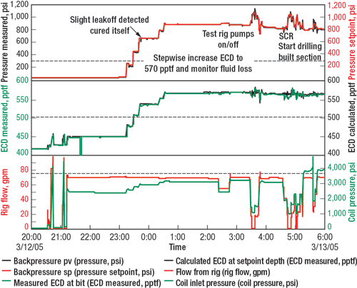
Once the window was milled, the DAPC system was checked. The pressure was slowly increased to provide an equivalent mud
weight (EMW) of 570 pptf, Fig. 4. The second channel shows the theoretical BHP values, along with the measured values from the pressure-while-drilling sub in the milling
BHA and shows a consistent correlation.
 |
|
Fig. 4. Once the window was milled, the pressure was slowly increased to provide an
equivalent mud weight of 570 pptf. The second channel shows the theoretical BHP values along with the measured values from the pressure-while-drilling sub. |
|
Once the desired EMW had been reached and the system checked for losses, checks were performed. These included stopping
and starting the rig pumps and pumping at various rates. As can be seen on the chart’s right-hand side, the downhole pressure varies considerably with flowrate
changes. The crews were still becoming familiar with the system and altering the pump rates too quickly for the DAPC system to react adequately.
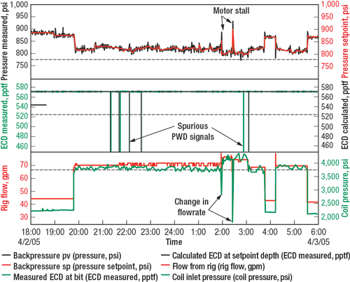
Drilling. The build section was drilled through the Tay reservoir from 10,927 ft to 10,982 ft with a maximum
dogleg of 43°/100 ft to a inclination of 93°. The DAPC system provided an EMW of 570 pptf during this time. Fig. 5 shows a sample of the drilling data.
 |
|
Fig. 5. The events shown in the plot are (left to right): Circulating while tripping in
to tag bottom, commencing drilling, including: wiper trips and stalls, change of flowrate to optimize drilling rate and reaming pass to clean part of the hole
section. The vertical lines on the measured BHP chart are anomalies in the PWD data, rather than measured values. |
|
Although the flowrate changes continuously and over a wide range depending on the operation, both the calculated and
measured BHP remained constant throughout.
The BHA was changed out and the tangent section drilled from 10,982 ft to 11,055 ft. On picking up off bottom the assembly
became stuck. After several days of attempting to free the BHA, the electrical disconnect was activated and 45 ft of fish were left in the hole.
Drilling progressed slowly to this depth. Weight transfer problems were experienced throughout the drilling that prevented
more than a couple of feet being drilled before the tubing locked up. Weight transfer to the bit was possible with the pipe moving at greater than drilling speeds, but as
soon as the feed rate slowed to below 30 ft/hr, the coil locked up. No weight could be transferred downhole, as seen by either the WOB sub in the BHA or by an increase in
differential pressure across the motor.
The issue with weight transfer and subsequent pipe movement across the open hole led to a deterioration of the filter cake
in the build section. The team decided to sidetrack at the contingency kick-off point rather than attempt to fish and continue with the existing hole.
A second whipstock was set at 10,870 ft and, after milling the window, the build section was drilled to 10,984 ft with a
maximum dogleg severity of 43°/100 ft. The tangent section was then drilled uphill at 98° inclination until sticking at 11,109 ft. At this stage, the team
completed the well.
The well was circulated to the 570 pptf completion mud and the 2-3/8-in. keystone slotted/ blank liner run. Although
running it was one of the highest risk operations, the liner was run without incident and set on bottom. The well was then displaced to base oil and after rigging-off the
CTD equipment, the well was shut-in for 35 days while the packers swelled.
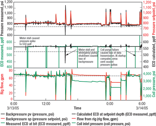
Unplanned events. As anticipated, there were unplanned events with the system. Fig. 6 shows a couple of motor
stalls. The DAPC system reacted quickly to the loss of flow, and the maximum loss of pressure was around 20 pptf, EMW downhole.
 |
|
Fig. 6. Unplanned events occurred. The system reacted quickly to the loss of flow, and
the maximum loss of pressure downhole was about 20 pptf, EMW. |
|
At approximately 15:45, a motor stall resulted in the primary mud pump shutting down. In this instance, the fluid pump
should automatically kick-in to replace the flow across the choke. Unfortunately, the fuse in the pump’s power supply failed. The choke manifold attempted to close
as quickly as possible to make up for the decreasing WHP, but due to the lack of flow, it was not able to retain any pressure. The BHP dropped to 435 pptf, EMW. Although
a shale section had been exposed in the open hole, the depressurization did not affect the quality of the borehole.
Further, the air purge system failed in the CT control cabin. The DAPC system lost a large proportion of the data being
sent. Because the mud pumps continued to run at the same flowrate, the system provided a stable BHP until the purge issue was rectified.
DAPC events. For the DAPC system, there were six discrete events that caused a loss of BHP. These events did not
cause catastrophic wellbore failure but would have contributed to wellbore weakening. The first sidetrack was terminated early after getting stuck. The incident appeared
to be related to hole debris.
The casing exit for the second leg was higher in the well, resulting in the window placement across a shale section.
Control of the BHP was vital while milling the window. During the second leg, the DAPC system did not suffer any failures.
The amount and proportion of downtime the system experienced during the complete operation can be seen in Table 3. The
reliability of the system was good. However, failure in a well of this type can lead to catastrophic failure of the wellbore. The reliability of the system can be
improved.
| TABLE 3. Non-productive events |
 |
|
Benefits. The DAPC system showed that it can be successfully applied to slimhole operations offshore. The system
provided a reduced overbalance on the formation during the operation that was consistently stable. The system eliminated the high potential of differential sticking while
drilling with a 2,000-psi overbalance.
The automated system provided a stable BHP and removed the complication of a manual choke. Both unexpected and planned
events were handled automatically without adversely affecting the BHP.
The reduction in weight of the base drilling fluid allowed for a much simpler mud system. This had dual benefits: a much
cheaper system and less effort to maintain mud properties.
PROJECT ACHIEVEMENTS
The project implemented CTD and DAPC successfully onto the Gannet platform, which had not seen drilling operations for
almost a decade. All of the work was performed with zero HS&E incidents, a considerable achievement considering the new personnel and the use of oilbase mud. There
was excellent integration with the platform, enabling numerous issues to be solved.
The project proved that CTD and DAPC could be used to access stranded reserves and almost tripled the original dry oil
production, achieving the P90 expectations, while reducing the BS&W from 70% to 7%.
The project proved the majority of the technical expectations by delivering:
- Two dual-casing exits, one unsupported
- Sections up to 43°/100 ft and tangent sections up to 98°
- DAPC proof-of-concept
- Uphill running of the 2-3/8 in. liner and swelling elastomer packers.
The ultimate reach was unconfirmed. Phase two of the CTD project aims to address this problem through the implementation
of a number of changes, not least by increasing the CT diameter from 2 in. to 2-3/8 in.
The benefits in the successful DAPC-CTD implementation on Gannet wells are two-fold. It shows that the remaining wells on
the Gannet platform can be accessed to recover additional reserves, and it expands the portfolio of drillable wells. 
ACKNOWLEDGEMENTS
The authors thank the management of Shell Exploration and Production and of ExxonMobil for permission to publish
this article. The contribution of the operational personnel involved is greatly appreciated. The authors also acknowledge the contributions made by Raj Fernandez of
Baker Hughes INTEQ; Martin Geddes and Barry Webster of Baker Oil Tools; Ken Hall and Michael Taggart of BJ Services; Egbert van Riet, Bjorn Vandecrean, Don Reitsma and
Russell Morris of @balance; and Paul Hague, Brian Hodgson, Jamie King, Martijn Kleverlaan, Robert Larsen, Toon Weisenborn, Dirk de Clercq, Pete French and Guus van Pelt
of Shell Exploration and Production.
This article was prepared from SPE paper 96404, which was presented at Offshore Europe 2005 in Aberdeen,
Scotland, UK, on September 6 – 9, 2005.
REFERENCES
1 Kara, D.T., Gantt, L.L., Blount, C.G., and Hearn, D.D., “Dynamically
overbalanced coiled tubing drilling on the North Slope of Alaska,” SPE paper 54496, 1999.
2 van Riet, E.J., Reitsma, D., Vandecraen, B., “Development and testing
of a fully automatic system to accurately control downhole pressure during drilling,” SPE/IADC paper 85310, 2003.
3 van Riet, E.J., 2003, “First field test dynamic annular pressure
control system on NAM Pernis well,” EP 2003-5524, Shell International Exploration and Production, Ltd (internal company report).
4 Weisenborn, T, “Gannet DES re-instatement cost estimate by the ISC,”
Shell UK Exploration and Production Ltd (internal company report), 2001.
5 Weisenborn, T., “Close-out of the alternatives for coil tubing drilling
on Gannet,” Shell UK Exploration and Production Ltd (internal company report), 2004.
THE AUTHORS |
| |
Andy Laird joined Leading Edge Advantage in 2000 and is lead engineer for the ongoing coiled tubing-managed
pressure drilling operation on the Gannet platform. Laird graduated from the University of Liverpool in 1990. |
|
|
Kathryn McFadzean is a CTD engineer with Leading Edge Advantage. McFadzean graduated from Strathclyde
University in 1998 and has worked for Read Well Services and Deutag before moving to her present position. She has worked on a number of underbalanced drilling and
coiled tubing drilling projects, including the Gannet coiled tubing-managed pressure drilling project. |
|
|
Jimmy Edgar is senior well engineer of completions for Shell UK’s Ormen Lange project offshore Norway.
Edgar was project manager (senior well engineer) for the duration of the Gannet coiled tubing drilling project. |
|
|
Ian Harty is offshore drilling supervisor with Shell UK and was part of the planning team for TTRD & CTD
wells, prior to moving into his current role. Harty earned an MSc degree in petroleum engineering from Imperial College in 1997. |
|
|


