Drilling Report
Codifying fracture closure stress and lost returns practices
Rock mechanics concept increases integrity by widening fractures.
Fred E. Dupriest, ExxonMobil
In the mid-1990s, lost returns mitigation practices were aligned with a simple, but robust, rock mechanics concept describing how lost circulation materials build integrity. The model held that integrity is increased by creating and widening a fracture, and the greater the fracture width achieved the greater the resultant integrity. Two critical requirements were established for all products: they must 1) achieve and sustain fracture tip isolation as wellbore pressure is used to widen the fracture, and 2) permanently prop the fracture with sufficient width, so the closing stress exceeds the circulating pressure needed to drill ahead. The manner in which various common products were used was changed to enhance their ability to achieve these two objectives, which resulted in a 100% worldwide success rate in permeable formations in 2003 (Fig. 1).
 |
Fig. 1. One year of lost returns data shows high success in permeable formations with enhanced practices and limited increase in FCS in low permeability formations. Many losses are treated by cutting mud weight.
|
|
For reasons discussed below, the success rate in building significant integrity decreases in low or damaged permeability. The fundamental rock mechanics requirements remain the same, but the two critical objectives are more difficult to achieve in low permeability. This article presents the development of the rock mechanics perspective and the resulting Fracture Closure Stress (FCS) treatments used across ExxonMobil’s global organization. A field-proven treatment selection guide, applicable to all fracture propagation losses, is also presented.
FRACTURE BEHAVIOR MODEL
The first step in selecting a treatment is determining the nature of the loss. Losses may be vugular, seepage (matrix), or fracture propagation. The subject of this paper is fracture propagation losses, which account for 90% of the operator’s major lost returns events. A fracture is opened when the wellbore pressure overcomes the sum of the stresses holding the hole closed and the tensile strength of the rock.4 Sedimentary tensile strengths are usually quite low and do not contribute greatly to the force required to open the wellbore. In contrast, the stress holding the borehole closed is often 75 – 85% of overburden, which is a very large value relative to the tensile strength. Though terms such as “weak zone” are often used in the industry, integrity is almost entirely a function of stored stress. Lost returns zones have low stress, not low strength. Therefore, most lost returns treatments function by changing the stress holding the fracture closed, which is referred to as the Fracture Closure Stress.
Operationally, it’s useful to view the rock stress holding the fracture closed as two components. The major component is the minimum principle far field stress created by the overburden.5 However, a second stress component – a near-wellbore stress riser – must also be overcome. When a hole is cut in a stressed material, this additional compressive stress develops in the immediate face of the hole due to tangential strain as the wellbore attempts to collapse. This stress was described in boreholes by Miles and Topping, 1949,10 and analyzed by Hubbert and Willis, 1957.1 The total compressive stress holding the opening to the fracture closed is the sum of the large far field stress and the additional smaller hoop stress riser in the near wellbore region. The total stress is the FCS. When losses begin to occur and hydraulic pressure acts on the face of the fracture, the near wellbore stress riser declines, and the FCS falls to equal the minimum far field stress.
BUILDING FCS
Nolte defined the FCS as equal to the fluid pressure required to open the fracture3 and field data shows this opening pressure to be reliable and repeatable.4 In order for the wellbore to sustain higher pressure, the closing stress on the fracture must be increased. The great majority of lost returns treatments achieve this by widening the fracture, not by “healing” or simply “plugging” it. In order to widen the fracture the adjacent, elastic rock must be compressed by a distance equal to the width. They greater the width, the greater the compression and increase in closing stress (Fig. 2). This stress is transmitted around the circumference of the wellbore and increases the opening pressure in other directions, though to a lesser degree than in the immediate area of the fracture. When the FCS treatment concept was developed in the mid-1990s, it was counterintuitive to believe that widening the fracture might be the main objective of a treatment scheme. The process had previously been described primarily in terms of fracture tip plugging.7 However, plugging of the tip alone does not prevent fracture growth, if the wellbore pressure is able to further widen the fracture because the plugged tip is bypassed as the fracture widens (Fig. 3). Recent numerical modeling and lab experiments now support the principle that width and the associated increase in closing stress determine the new integrity (fracture opening pressure).7,8,9 Engineers believe that virtually all common lost returns treatments operate on this principle, including conventional lost circulation materials (LCM), crosslinked polymers, cement, adhesive solids and Stress Cage treatments.
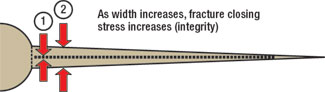 |
Fig. 2. Fracture closure stress is increased by widening the fracture to compress the adjacent rock. Closing stress determines opening pressure. Losses cannot occur if FCS > ECD.
|
|
 |
Fig. 3. Losses are not stopped by simple plugging. Effective treatments must simultaneously isolate the tip and achieve adequate width so that FCS > ECD.
|
|
The challenge in creating fracture width is building pressure within the fracture to compress the adjacent rock. As a fracture initiates, filtrate will begin to flow into the opening. If the wellbore pressure is high enough, the opening will be driven to a width capable of accepting the solids in the drilling fluid and whole mud will begin to flow into the fracture. Since barite particles are 0 – 100 microns in size, the required fracture width for losses to occur with a barite-laden mud is assumed to be around 100 – 200 microns. At this point, fluid can travel into the fracture to the tip. Because tip propagation pressures are usually quite low (20 – 30 psi), it is not possible to build pressure if mobile mud is in contact with the tip.
This assumed progression of events suggests that any successful treatment must achieve two objectives simultaneously:
- The material must achieve and maintain isolation of the tip as the fracture widens
- The pressure build up must achieve a final width corresponding to a closing stress greater than effective circulation density (ECD).
Differing approaches, such as conventional LCM, cement, adhesive solids, viscous setting systems, and Stress Cage treatments achieve these objectives in different ways, but both objective must be met in all cases.
There are a number of practical operational implications:
- Fracture growth is not stopped by plugging the tip. The width at the extreme tip will always be zero, so the increase in closing stress at the extreme tip cannot be positive.
- The fracture is not a fixed gap width. The blocking mechanism must shift or deform to maintain tip isolation as the fracture widens under increasing pressure.
- The greater the required increase in FCS, the more difficult it will be to achieve, because the blockage must withstand differential pressure across a wider fracture.
- It’s difficult to maintain tip isolation in very short fractures, if a significant increase in width is required. This may pose logistical problems for schemes to arrest fracture growth quickly by pre-treating the mud with LCM.
THE IMMOBILE MASS
LCM is believed to isolate the fracture tip by becoming immobile due to the loss of its carrier fluid (Fig. 4a – 4c). Initially, there is very little resistance to flow down the fracture. While the slurry is mobile, it does not isolate the tip and the width is only that required for the barite-laden mud to travel down the fracture.6 It is assumed immobility develops due to the leak-off of carrier fluid from the LCM into the permeable rock face. The solids remain in the fracture and at some point they lack the carrier fluid required to be mobile. As the resistance to movement increases, pressure can be supported to further widen the fracture. The loose particles in the immobile mass then shift to maintain tip isolation, as the width increases with increasing wellbore pressure.
 |
Fig. 4a – 4d. Width is built by isolating the tip with an immobile mass, so that pressure can be applied, and/or by depositing material in layers.
|
|
Field experience supports the belief that particle size is relatively unimportant. Any pill will become immobile if it loses sufficient carrier fluid. Materials with a D50 of 400 microns are used for all treatments, because it can be pumped reliably without tripping to lay down LWD and motors that may plug with larger solids. Increases of 0 – 3,800 psi have been achieved, and numerical modeling has shown that the fracture width required to achieve these stress levels greatly exceeds 400 microns. High fluid loss, and not larger LCM, is needed.
In the mid-1990s, practices were created to maximize the development of the immobile mass. These are often referred to as FCS treatments, though it is important for the industry to understand all treatments of fracture propagation losses are “FCS treatments” in that they build FCS. Any material or process the operator is using today may be made more effective if modified to better achieve the two critical objectives discussed above. In general, the manner in which LCM is used is more important than the type or size. Research and field trials lead to the following conclusions:
- The first step in treatment selection is to determine whether the losses are due to matrix or fracture propagation. Materials smaller than barite (0 – 100 microns) tend to reduce leak-off and should not be used in fracture propagation treatments where high fluid loss is needed to create the desired immobile mass.
- LCM should not be mixed in whole mud except in very high permeability or severe drawdown. Drilling fluids contain fluid loss control agents that inhibit leak-off and the development of the immobile mass.
- LCM particle size may be unimportant with the operator’s treatment methodology.
- In barite-laden mud, LCM serves as a fluid loss enhancer and not necessarily as a blocking agent. When a larger particle is mixed with a barite-laden mud, the fluid loss increases. Fig. 5 shows the effect of mixing 100 ppb of 400-micron LCM into a 12.0-ppg pill containing 200 ppb of barite. The fluid loss increased from 9 cc to 17 cc.
- An alternative approach to enhancing fluid loss with LCM is to remove the small barite particles inhibiting filtrate loss and the development of the immobile mass. Fig. 4 shows that, when the fines below 30 microns are removed from barite, the fluid loss increases 10-fold. Pills constructed of low-fines barite alone and no LCM have proven to be as effective as those containing LCM.
- The effect of barite fines on fluid loss may be reduced by using suspension agents that do not viscosify the water phase. Fig. 5 shows the spurt loss from a pill suspended in attapulgite may be extremely high, whether API or low-fines barite is used.
- LCM size should be as uniform as possible to maximize fluid loss (Fig. 7). Blended LCM sizes are useful for matrix seepage losses because they allow a range of pore throats to be blocked. In contrast, uniform particle sizing and shapes with poor packing efficiency are preferred to maximize fluid loss in FCS pills.
- The type of LCM used is unimportant. Any material will become immobile when it loses its carrier fluid. The successful wells shown in Fig. 1 used materials as diverse as nut hulls, graphite, frac sand, coarse barite and sawdust with apparent equal effectiveness.
- Pills should maximize the starting solids content by percent volume, up to the limit of pumpability. LCM should be chosen by its density, and content should be specified by percent solids, not pounds per barrel.
- The percent volume of larger particles in a given pill is increased by using dense LCM such as coarse barite (specific gravity 4.3) or calcium carbonate (s.g. 2.7) rather than lighter material such as nut hulls (s.g. 1.2).
- The compressive strength of the LCM is relatively unimportant. The immobile mass is built of material that is already exposed to a high crushing force, first from hydrostatic head and second from point loading during the squeeze process. There is little gross volumetric change after the fracture closes on the solids.
- Because there are no agents for suspending LCM in non-aqueous fluids (NAF) that do not also reduce fluid loss, water-based pills are used in non-aqueous fluids. There have been no borehole stability problems in the last nine years of experience. It is believed the oil-wetting surfactants used in NAF remain attached to the formation surface and continue to prevent water uptake during the brief period of the squeeze operation.
 |
Fig. 5. LCM functioned as a 2X spurt loss enhancer in the 12.0 ppg mud by diluting the plugging effect of barite fines. Elimination of the fines below 30 microns was more effective, and created a 10X increase.
|
|
 |
Fig. 6. Barite fines inhibit fluid loss, but only if suspension agents are used that viscosify the water phase.
|
|
 |
Fig. 7. Pressure increase during initial placement indicates permeability in the fracture face, rapid development of immobile mass, and increasing NFP and FCS.
|
|
HESITATION SQUEEZING
Severe losses are treated by hesitation squeezing (Fig. 4a – 4d). If the well will not stand full, the annulus is stabilized with a Hydrostatic Packer. When the treatment is bullheaded it is followed with a similar drill string Hydrostatic Packer to prevent overdisplacement.11 Treatments are not effective if the LCM is over displaced. The use of Hydrostatic Packers is essential to prevent this, so sufficient LCM is retained above the loss zone in the wellbore to enable several squeezes. If the well can be circulated with full returns, the pill is balanced rather than bullheaded and packers are not required. In a typical hesitation treatment, 20 bbls of LCM are displaced into the fracture and 60 – 80 bbls are held back in the wellbore. Any initial squeeze pressure achieved is held to prevent backflow of the pill.
The annulus pressure is recorded continuously throughout the job. Any change in surface pressure is a direct indication change has occurred in fracture closure stress while squeezing, or while shut-in. After the initial volume is placed into the fracture, the well remains shut-in until the carrier fluid in the fracture has had time to leak-off, leaving the solids behind in the fracture. When the next 20 bbls are squeezed, the original material is assumed to be held in place along the fracture faces by differential pressure in the same manner as a filter cake, and the new material is deposited alongside it. Pressure is again held until leak-off of the carrier fluid has occurred and the process is repeated. The fracture width is built in layers. The fracture tip is never truly isolated because the required immobile mass does not develop. The treatment succeeds when the accumulation of layers provides enough fracture width to create a FCS greater than the ECD.
INTERPRETING FIELD DATA
The pattern of pressure response while squeezing LCM is usually similar to one of the three examples shown in Figs. 7, 8 and 9. These are interpreted as high permeability, low permeability and impermeable responses. The interpretation is important and determines the next step to be taken if the initial treatment is ineffective. If a low-perm pattern is seen, the use of conventional LCM is discontinued immediately and low-perm products are shipped to location.
Fig. 7 shows data from a successful treatment in a permeable drawdown zone with a high fluid loss, high solids pill. Pressure was monitored on the annulus as the FCS built steadily as the first 20 bbls were pumped into place at a low rate. The rate and character of increase in surface pressure during the squeeze is a direct reflection of the rate at which the immobile mass is developing, the resulting build-up of NFP and width, and the increase in FCS achieved. In this case, the zone is judged to be permeable because of the rapid development of the immobile mass. After waiting two hours, the second 20 bbls were squeezed. The fracture’s opening pressure was 17.5 ppg. The increase in opening pressure from 15.9 ppg to 17.5 ppg occurred because the starting position of the fracture width is now greater. The adjacent rock is now compressed to yield a closing stress of 17.5 ppg. Subsequent squeezes did not increase the FCS beyond 17.8 ppg because this is the opening pressure of the adjacent shales. The integrity in the sand is now higher than its original pre-depletion value. There are no documented cases where the integrity while drilling ahead was less than the increased fracture opening pressure observed during hesitation squeeze operations with LCM (the same cannot be said of viscous systems). The FCS holds the immobile mass in place, and the immobile mass prevents loss of width and closure stress indefinitely. Integrity has only been lost when the applied wellbore pressure inadvertently exceeded the enhanced closing stress, allowing the solids to remobilize as new mud entered the fracture.
Fig. 8 shows an example of a squeeze in low or NAF-damaged permeability. The fracture opening pressure on the initial squeeze was 300 psi. After the fracture was reopened, the entire initial 20-bbl squeeze was pumped with little change in pressure. This pressure plot character is an indication the leak-off rate is too slow for significant immobility development during placement. Because there is very little change in fracture pressure, there is little change in width during placement. After shut-down and holding pressure for two hours, the second hesitation was pumped, increasing the opening pressure to 500 psi. The increase in opening pressure indicates the solids layer deposited during the first squeeze is held in place. The fracture must now grow to a greater width before additional LCM can enter beside the layer that is already in place. Again, the opening pressure continued to increase as more layers were deposited until the FCS exceeded the stress in the boundary shales.
 |
Fig. 8. Small or no increase during placement indicates low permeability and poor development of immobile mass. Fracture width and FCS are built in layers, by hesitation squeezing. Final FCS equals the boundary shale integrity.
|
|
Fig. 9 shows an unsuccessful squeeze in an impermeable formation. The key diagnostic for a lack of permeability is the fracture opening pressure at the start of each hesitation. If the pressure is not changing, the width cannot change. For the fracture to accept new material without a change in width, the previous solids must still be mobile and traveling down the length. This indicates the permeability is low and there is inadequate differential pressure into the rock face to hold previous material in place.
 |
Fig. 9. Fracture opening pressure is not changing with each new hesitation squeeze, indicating inadequate permeability for LCM to be effective.
|
|
IMPERMEABLE OR NAF-DAMAGED FRACTURE FACES
There are no observed cases where LCM was effective in a truly impermeable formation such as shale, although successful treatments have been achieved in ideal conditions in permeability as low as 0.1 md. Because LCM has not been effective, impermeable formations are treated with specialty products that do not require leak-off. Each is evaluated according to the same criteria established for conventional LCM: the ability to achieve and maintain tip isolation, and the ability to achieve the desired width. These include crosslinked polymers (Fig. 10), and adhesive solids. The success of these treatments has been limited. Repeated treatments are often required, and the maximum integrity increase achieved has been in the range of 200 – 300 psi. While this is adequate to stop many ballooning fracture losses, significantly greater increases are needed in some situations. One proprietary viscous material with higher extrusion resistance has been used successfully to achieve greater increases in FCS, but its use has been limited by displacement problems when the loss zone is located well below the shoe.
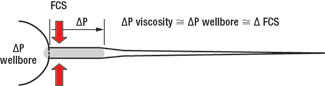 |
Fig. 10. The FCS that can be achieved with a viscous system equals the differential pressure the material can resist before extruding to transmit pressure to the tip.
|
|
TREATMENT SELECTION GUIDE
The Treatment Selection Guide (Fig. 11) is used by ExxonMobil to match the lost returns response to the need. The graphic reflects the issues that determine the difficulty in treating a particular loss event. If little increase in FCS is required and the formation is very permeable, the immobile mass develops rapidly and treatment is not difficult. Simple treatments may be effective.
 |
Fig. 11. Losses are characterized according to the difficulty in obtaining leakoff from the LCM material, which depends on permeability, the required increase in fracture width and FCS, and the differential pressure between the pill and formation.
|
|
As the permeability declines or the required fracture width increases, field practices are enhanced through the use of high fluid-loss pills and hesitation squeezing. In the most difficult low permeability cases, all of the FCS treatment enhancements may be employed. The guide also shows stress is more easily built in drawn-down pays where high differential pressure aids the dehydration process, and a less aggressive treatment may be selected.
Finally, if the formation is impermeable, or if data analysis from the first attempt with an LCM pill shows a lack of permeability, the use of LCM is abandoned and specialty products are used. At least 40% of the ExxonMobil’s lost returns events are not treated at all (Fig. 1). They are resolved by cutting fluid density so the ECD is less than FCS and losses cease.
CONCLUSIONS
FCS treatments were developed based on the belief that integrity is built by increasing the fracture width, regardless of the product used. The concept applies to industry practices as diverse as conventional LCM, cement, crosslinked polymers, adhesive solids and Stress Cage treatments. To stop lost returns, all effective treatments must achieve two objectives: maintain isolation of the tip as pressure is applied to widen the fracture, and achieve a final blocked width sufficient for the closing stress to exceed ECD.
Field procedures were modified in the mid-1990s to allow common LCM materials to achieve these objectives, either through the more rapid development of an immobile mass or layering of materials with hesitation squeezing and Hydrostatic Packers. A treatment selection guide was developed based on these factors. The success rate with common LCM is close to 100% in permeable formations. Additional progress is needed in low or damaged permeability.
This article is based on SPE/ IADC 92192, which was prepared for presentation at the SPE/ IADC Drilling Conference held in Amsterdam, the Netherlands, February 23 – 25, 2005. 
ACKNOWLEDGMENTS
The perspectives discussed in this article came from years of analysis and continuous redesign of field practices. Literally hundreds of engineers and rig supervisors have contributed. The author acknowledges the hard work required to plan, execute and analyze lost returns operations, and the rigor of the drill teams in aligning the field practices with the rock mechanics concept.
REFERENCES
1 Hubbert, M. K. and Willis, D. G., “Mechanics of Hydraulic Fracturing,” Petroleum Transactions, AIME (1957), vol 210, pp. 153 – 166.
2 Jaeger J. C., Cook N. G. W., Fundamentals of Rock Mechanics, Halsted Press, New York City (1976)
3 Nolte, K. G., “Fracture Design Considerations Based on Pressure Analysis,” SPEPE (February 1988), pp. 22 – 30.
4 Bratton, T. R., Rezmer-Cooper, I. M., Desroches, J., Gille, Y-E., McFayden, M., “How to Diagnose Drilling Induced Fractures in Wells Drilled with Oil-Based Muds with Real-Time Resistivity and Pressure Measurements,” SPE 67742 presented at 2001 SPE/ IADC Drilling Conference, Amsterdam, February 27 – March 1, 2001.
5 Kunze, K. R. and Steiger, R. P., “Accurate In-situ Stress Measurements During Drilling Operations,” paper SPE 24593 presented at 1992 SPE Technical Conference, Washington, DC, October 4 – 7, 1992.
6 Morita, N., Black, A. D., Fuh, G-F, “Theory of Lost Circulation Pressure,” SPE 20409 presented at 1990 Annual SPE Technical Conference, New Orleans, September 23 – 26, 1990.
7 Fuh, G-F, Morita, N., Boyd, P. A., McGoffin, S. J., “A New Approach to Preventing Lost Circulation While Drilling,” SPE 24599 presented at 1992 SPE Technical Conference, Washington, DC, Oct. 4 – 7, 1992.
8 Sanad, M., Butler, C. Waheed, A. Engleman, R. and Sweatment, R., “Numerical Models Help Analyize Lost-Circulation/ Flow Events and Frac Gradient Increase to Control an HPHT Well in the East Mediterranean Sea,” IADC/ SPE 87094 presented at 2004 IADC/ SPE Drilling Conference, Dallas Texas, March 2 – 4, 2004.
9 Alberty, M. W., Mclean, M. R., “A Physical Model for Stress Cages,” SPE 90493, presented at SPE Annual Technical Conference and Exhibition, Houston, Texas, September 26 – 29, 2004.
10 Miles, A. J., Topping, A. D., “Stresses Around a Deep Well,” Transaction AIME (1949) 179, p. 186
11 Dupriest, F. E., “Fracture Closure Stress (FCS) and Lost Returns Treatments,” SPE 92192, presented at 2005 IADC/ SPE Drilling Conference, Amsterdam, February 23 – 25.
THE AUTHORS
|
 |
Fred E. Dupriest earned a BS in mechanical engineering from Texas A&M University in 1977. He has 29 years with ExxonMobil in various operational, engineering, and technical drilling assignments. Dupriest is assigned to Drilling Technical in Houston and supports the worldwide organization with trouble event response, emerging technologies, and operations and engineering training. He may be reached at fred.e.dupriest@exxonmobil.com.
|
| |
|
|

