Developing a subsea compressor for marginal field production
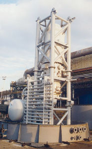
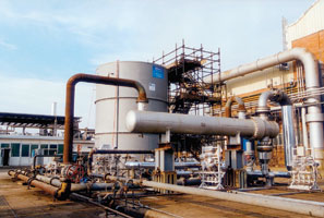
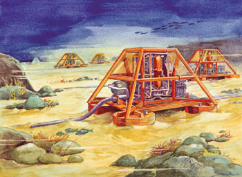
Production TechnologyDeveloping a subsea compressor for marginal field productionA project to build the first subsea centrifugal compressor module has passed its first battery of tests and is ready for field testingLeonardo Baldassarre, Stefano Terzi and Sabrina Tasselli, GE Oil & Gas Nuovo Pignone, Florence, Italy Certain subsea fields in water depths up to 500 m are not profitable because the cost of conventional platforms is too high for the expected return; so, these fields remain marginal and thus, unexploited. A breakthrough technology solution is a subsea centrifugal compressor module, installed on the seabed, that transports the wellstream to a central platform or onshore. A typical application is gas boosting, but it can also be used in re-injection service. Reliability is an essential requirement of module operation. To validate the design and minimize field risks on future units, thermodynamic and mechanical performances must be verified throughout their operating ranges in test facilities. Norway and other countries are funding and leading programs to develop systems aimed at economically exploiting marginal subsea resources. DEMO 2000 is a program for qualifying deepwater technology by pilot demonstration. It was launched in 1999 by the Norwegian government to finance projects deemed to represent a technology breakthrough. An operator committee comprising several major oil companies selected the Subsea Centrifugal Compression Module Development among the projects to be hosted under the DEMO 2000 umbrella. Introduction The project started with refurbishment and testing of a 850-kW prototype, originally developed in 1992 by GE Oil & Gas Nuovo Pignone and Kvaerner Eureka, to validate the concept and to identify technology gaps before completing the detailed design of a new module, Fig. 1. The two companies are co-developing a 2.5-MW subsea centrifugal compressor module comprising a package and a compression train (BLUE-C compressor line). The construction and testing program of the 2.5-MW prototype will be completed by a pilot installation and final qualification in the North Sea, offshore the Norwegian coast.
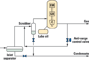
Module Configuration The compressor train, vertically arranged, comprises a centrifugal compressor, a planetary gearbox and a variable speed electric motor; a separator can be included, as an option. One of the main features is that all the three casings (centrifugal compressor, gearbox and electric motor) are directly bolted together. The planetary gearbox allows alignment on the same axis as compressor and gearbox shafts, thus greatly simplifying the casing connections. The entire compressor train is internally pressurized at the reference pressure, which is the compressor suction pressure, Fig. 2.
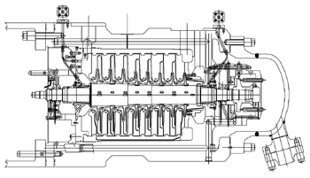
Subsea Compressor The 2.5-MW subsea compressor, complying with API 617, is barrel type, with six in-line 2D impellers, an architecture that is standardized and well proven. The machine is designed to compress 900 m3/hr of natural gas (with a molecular weight close to 19) to 130 barA from 65 barA. Casing design pressure is 200 barA. The machine is equipped with standard oil tilting pad journal and double side leveling plate thrust bearings. Reliability is one of the most important considerations in development of the subsea compressor. Therefore, only proven and well-referenced solutions and components are selected. It is important to design a machine with a safe lateral behavior and very low vibration levels to avoid any possibility of seal damage, with consequent extra maintenance. To achieve this goal, attention was given to maximizing rotor stiffness by using few stages and large rotor-shaft diameter. Except for the different number of stages and the power, the 2.5-MW unit design was derived from the tested 850-kW unit. Some improvements in the end-seal design and oil system have been introduced to optimize lubrication and further reduce oil consumption, Fig. 3.
All subsea module components are pressurized at the compressor suction pressure. In principle, no differential pressure exists at the shaft end, so there is no need for end seals. However the compressor is equipped with buffered end-labyrinth seals to prevent oil flow from the journal bearings to the process gas. Oil consumption is a critical aspect of the project, because the oil tank is filled during commissioning and refilling must wait until the next planned maintenance – not during module operation. Abnormal oil consumption could determine the need for unscheduled maintenance, with important impact on field productivity. The differential between buffer gas and suction pressure can be maintained to minimum values (down to 0.2 bar) to reduce, as much as possible, buffer-gas consumption that affects overall compressor efficiency. The absence of mechanical seals represents an important simplification in machine architecture, improving reliability and maintenance intervals, with a positive impact on rotor-bearing span. The presence of CO2 in the gas requires materials able to withstand general corrosion. In fact, even if no liquid water exists in the gas during normal operation, during transients or pressurized shut downs, the presence of cold water around the compressor casing can cause water to condense in the gas. For this reason, all static compressor components are made of stainless steel. Impellers are also built with materials able to withstand wet CO2. Special materials are available in case of gas containing H2S, without any reduction in machine life / reliability. The thermo-fluid-dynamic design of the machine must take into account the effect of heat exchanged between the process gas and the external cold water (down to – 1°C) surrounding the module. In practice, gas coming from one stage is cooled before going to the next, as if compression would be inter-refrigerated. If correctly evaluated, this results in an efficiency increase of the machine compared to onshore applications. Upstream of the compressor flange, there is a gas-liquid separation system followed by a cyclone scrubber. The purpose of this system is to protect the compression module against potential liquid intrusion in an efficient and reliable way. As already remarked, the risk of having liquid particles inside the compressor has to be avoided as for any conventional applications. Further steps are envisioned in development of the subsea module, such as:
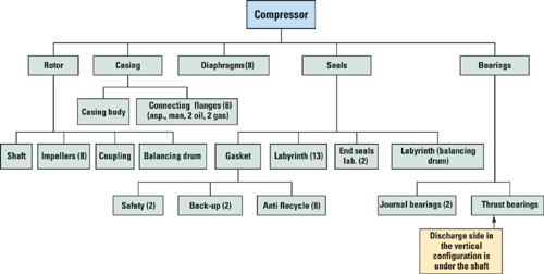
Compressor Reliability Approach Centrifugal compressor reliability is an essential requirement to guarantee machine performance. On one side, the reliability design comprised a preliminary Flow Down, which was realized starting from the preliminary Process & Instrument Diagram (P&ID). All the main components and subsystems, i.e., compressor , auxiliaries (seals, lube oil and anti-surge systems, sensors) are to be taken into account to avoid misinterpretation of system working conditions showing in the Reliability Block Diagram (RBD), Fig. 4
On the other side, a Failure Mode and Effects Analysis of each subsea compressor component was performed based on an existing barrel compressor project of the same casing size. Then, due to the particular underwater machine application and configuration, some gauge parameters and additional conditions were introduced to consider the environmental impact in failure situations and the fact that no corrective maintenance actions could be performed. Starting from the Flow Down structure and P&IDs, the RBD was created considering only components whose failure cause the machine to stop, without considering non-critical components. Critical components are described by failure distributions derived from the company’s proprietary reliability database, created from field data from its machines with the support of other reliability databases. RBD realization is very important to introduce data into reliability and availability software, which simulates the life of a system with a monte-carlo method by random numbers generation. While completing the RBD, a number of different conditions and configurations were analyzed to evaluate the preliminary design reliability value. Feedback to the engineering department allowed improving the system reliability figures by means of redundancy strategies, or by using components with higher reliability. Reliability and availability simulations were performed by means of three software programs that are fundamental to studying such systems, since it would be too expensive and time consuming to perform an accelerated life test. Availability figures are not the main aspect of this study because, due to the subsea location, no corrective maintenance actions should be considered (zero failure is envisioned) to guarantee operator expectations. Full Load Module Testing The new designs applied in the subsea centrifugal compressor module needed to be validated to minimize failure risk in the field on future units. This led to refurbishing the 850-kW prototype, introducing on it the technological improvements dictated by experience from the first testing program that was performed in the early 90s. The purpose of the tests was to confirm thermodynamic and mechanical performance of the machines over their operating ranges, and to verify that the design would work properly in the subsea environment; all of which was accomplished before starting detailed design and construction of the new units (2.5/5.0 MW). A complete test campaign was performed, based on a full-load underwater string test of the complete compression train, including the most critical auxiliary systems. During this test, an API 617 mechanical running test, an ASME PTC10 Class 1 test and a 500-hr endurance test were performed. The subsea compressor module with its auxiliaries was installed under-water in a dedicated testing facility consisting of a special tank. A process gas closed loop was set up with all the necessary shop auxiliaries (throttling valves, water / gas heat exchangers, process flow measurement devices, safety valves, gas analyzer) and including transfer and filling system for process gas mixture (natural gas and CO2). In these types of tests, the process conditions are reproduced very closely: process gas characteristics (flows, pressures, temperatures), machine speeds, power absorbed, etc. These tests allow a thorough analysis of the thermodynamic and mechanical behavior of the entire module, including compressor performance curves, surge limit, machinery vibrations both in steady state and transient conditions, power absorbed and efficiencies. In addition, auxiliary systems were also fully verified, Fig. 5. By means of a few additional devices and instrumentation inside the compressor, it was possible to analyze the whole lube-oil system integrated on the module, as well as to verify the flow direction under the labyrinth seals to avoid the risk of oil flow from bearing to gas path.
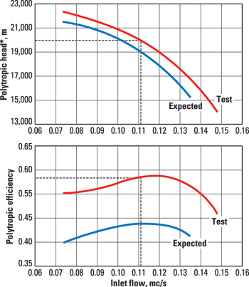
Test goals included checkouts of the mechanical behavior of the complete train by means of measurement of vibration, of bearing babbit temperature and lube-oil system parameters. Vibration diagrams were plotted (frequency analysis at 100% speed, run down and run up diagrams) with a shop vibration data-acquisition system. The characteristic compressor curves measured during the test were reported and compared to those predicted during the engineering phase. During these tests, special care was taken to examine the mechanical behavior of the compressor after the 500-hr endurance test. In particular, the vibration level of the rotors was very low and in accordance with API specs. The results confirm that the compressor satisfied the performance requirements, Fig. 6. Auxiliary systems also performed properly under all operating conditions. The testing data was collected to validate the final technical solution for the new generation of subsea compressors based on 2.5 and 5.0-MW drivers, Fig. 7.
Conclusion The first subsea module will follow a technological qualification process under real operational conditions on a subsea gas field. Initially, the module will be installed on a platform to perform pre-qualification tests. After that phase, it will be submerged to a 300-m depth, and the qualification protocol will be continued. Meanwhile, feasibility studies with some oil companies have already been performed for potential opportunities in the North Sea, for both gas boosting and gas re-injection. Looking at future offshore and deepwater field assets, current technological developments are focusing more on the seabed rather than on the platform. This is clearly a tough challenge, but it can represent the real breakthrough for years to come. Acknowledgment The authors thank the following contributors to the development of this paper: Kjell-Olav Stinessen, Kvaerner Eureka Development Manager-Subsea Rotating Equipment; and Mehdi Navidi, Kvaerner Eureka Project Manager of the Subsea Centrifugal Compressor Module.
|
||||||||||||||||||||||||||||||
- What's new in production (February 2024)
- U.S. operators reduce activity as crude prices plunge (February 2024)
- U.S. producing gas wells increase despite low prices (February 2024)
- U.S. oil and natural gas production hits record highs (February 2024)
- Dallas Fed: E&P activity essentially unchanged; optimism wanes as uncertainty jumps (January 2024)
- Mixed outlook for activity on the UK Continental Shelf (December 2023)

