Well remediation using expandable cased-hole liners
Oil Country Tubular GoodsWell remediation using expandable cased-hole linersSolid expandable tubulars as openhole and cased-hole liners (CHL), and expandable liner hangers have proven effective in field operations, as illustrated by two CHL case historiesRandy M. Merritt and Rune Gusevik, Enventure Global Technology; and William Buckler and Nick Steinsberger, Mitchell Energy Co., L.P. This article briefly describes the technical concepts on which Solid Expandable Tubulars (SET) are based and gives an overview of their applications. The paper then focuses on two recent field installations in which cased-hole liners were used to help increase well productivity. Even with rapidly evolving technology, important issues that continue to challenge the oil and gas industry include conservation of hole size, hydraulic isolation of selected zones, maximization of well life and economic feasibility. Addressing these issues with conventional tubular technology became more difficult – especially in deep-drilling and extended-reach applications – in wells using liner hangers, and in aging wells containing deteriorating casing. SET, a revolutionary technology, successfully addresses these issues in commercial applications. The basic piece of equipment underlying SET technology is a mechanical expansion device known as an expansion cone that is propagated through downhole tubulars using hydraulic pressure. Cone movement expands the tubulars to the desired internal and external diameters in a plastic-deformation process known as cold drawing. In drilling applications, a specially designed, expandable liner hanger conserves hole size by eliminating need for a conventional liner hanger / liner hanger packer, and provides a superior pressure seal, compared to conventional technology. In cased wells, expandable casing is clad to existing casing to repair or strengthen the existing casing, with minimal decrease in wellbore inside diameter (ID) and flow potential. SET solutions have been successfully installed in more than 60 wells globally, both in deep offshore water and onshore in the Gulf of Mexico, in U.S. inland wells, as well as in large-scale field trials. Technology Overview Previously published papers have discussed the concepts of SET technology1 and effect of the expansion process on the system’s tubulars2,3 and connectors.4 In this light, the basics of the technology will be reviewed, and the emphasis will be on how this technology was applied to remediate wells to increase productivity from subsequent operations. As noted, the underlying concept of solid expandable casing is cold drawing steel tubulars to the required size downhole – a process that is mechanically very unstable by its nature. Thus, there are many technical and operational hurdles to overcome when taking the cold working process and accomplishing it in a downhole environment.
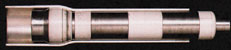
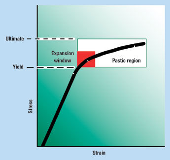
An expansion cone mechanically deforms the pipe permanently, Fig. 1. The cone is propagated through the tubular by a differential hydraulic pressure across the cone itself and/or by a direct mechanical pull or push force. The differential pressure is applied by pumping through a workstring connected to the cone, and the mechanical force is applied by raising or lowering the workstring. Progress of the cone through the tubular deforms the steel past its elastic yield limit into its plastic deformation region, stopping short of its ultimate yield strength, Fig. 2. Expansions of more than 25%, based on pipe ID, have been accomplished – most applications require less than 20%.
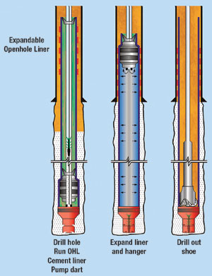
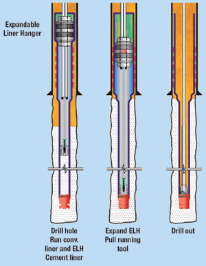
At the bottom of the system is a canister containing the expansion cone. This canister is called the launcher, which is constructed of thin-wall, high-strength steel, with a wall thickness less than the drift of the previous string of casing. This design enables the launcher to be tripped into the hole through the previous casing string. An elastomer-coated hanger joint is positioned at the top of the expandable system – just above the launcher for cased-hole applications. The difference in OD of the expanded tubular and ID of the base casing allows the elastomer-wrapped expanding pipe to be "clad" (sealed) to the previous casing string. After expansion, the result is expanded pipe with an OD greater than the OD of the launcher (due to the small wall thickness), while the ID of the pipe expands to the same ID of the launcher. Solid Expandable Tubular Products The following expandable products are derived from SET technology; 1) Expandable Openhole Liner (OHL) system; 2) Expandable Cased-Hole Liner (CHL) system; and 3) Expandable Liner Hanger (ELH). Expandable Openhole Liners. The OHL system is used to overcome operational problems associated with borehole instabilities, pore-pressure / fracture gradient issues, and effects of salt or subsalt formations. The OHL is run through the existing casing or liner and positioned in the openhole. The expandable OHL is then expanded from the bottom up. When the expansion cone reaches the overlap between the expandable OHL and the existing pipe string, the cone expands an elastomer-wrapped hanger joint to provide a permanent seal between the two strings. OHLs are expanded from the bottom up due to the shortening of the liner during expansion and because it is easier to generate greater forces by pumping through and pulling on the workstring than it is by adding weight to the workstring. Liners are often difficult to position at their planned total depth and, consequently, may be positioned somewhat higher. A top-down expansion would first anchor the expandable liner in the previous pipe string, and the ensuing expansion would shorten the liner from the bottom up. The shortened, expanded liner may not cover an adequate interval at the bottom of the hole. A bottom-up expansion first anchors the expandable liner at its lowest depth, and the subsequent shortening experienced during the remaining expansion occurs in the overlap. Liner coverage at the bottom of the hole is thus ensured. Because the workstring is already being pulled out of the hole as a part of the bottom-up expansion operation, additional tensional forces can be added to the workstring, if necessary, to serve as a secondary force to drive the expansion. With a top-down expansion, downward force or additional weight to the workstring would serve as the secondary expansion force, placing the workstring (drill pipe) in compression. Drill collars and heavyweight drill pipe would be needed as part of the workstring to supply additional weight. This would only add time to workstring makeup, with minimal compressional forces being added in comparison to the tensional forces available. For example, propagation forces in expandable operations when expanding 13-3/8-in. casing can approach 300,000 lb. The casing’s size and mechanical properties typically determine the propagation forces required to expand the liner. The following steps outline the running sequence for the installation of the expandable OHL, Fig. 3.
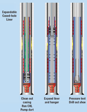
Expandable Cased-Hole Liners. The CHL system is used to repair or reinforce existing casing. The system is mechanically similar to the expandable OHL system, except that the elastomer-wrapped hanger joints are located at both the top and bottom of the assembly. The CHL system can be run in two modes: open-ended or bull-plugged. In the open-ended system, the latch-down dart is pumped after the system has been run into the well and positioned. In the bull-plugged mode, the system is run into the well and positioned with the latch-down dart in place. In the latter mode, the liner is filled with fluid when run to prevent collapse. Because the bull-plugged mode eliminates one operational step, thus reducing time on location, this mode may be preferred in shallow and low-pressure environments. The following steps outline the running sequence for installation of the expandable CHL, Fig. 4:
Expandable Liner Hangers. The ELH system is run when a conventional liner is used. Machined from a single bar stock, the ELH joint does not have the threads, slips, J-slots and weep holes found in conventional liner-hangers. A wiper-plug system or a subsurface-release plug kit is attached to the bottom of the joint. Inside the joint, a toroidal expansion cone, mounted on a mandrel, runs the length of the joint. Collets lock the mandrel to the bottom of the joint, supporting the liner’s weight and allowing the liner to be rotated and reciprocated during installation. Tests have indicated that the ELH system provides a better pressure seal when compared to conventional liner hanger systems with packers. The following steps outline the running sequence for the installation of the ELH, Fig. 5:
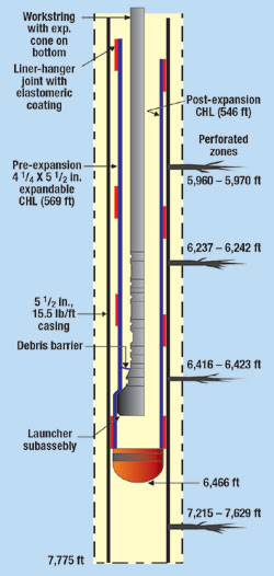
Expandable Applications Probably the most significant advantage of solid expandable products is its enabling technology. Currently, certain critical wells cannot be drilled to their objectives without SET technology. An example of this would be ultra-deepwater wells (over 5,000 ft TD), where the operator uses every casing string available in the well design, yet the drilling environment requires more casing points than there are casing sizes. Cost-effective well remediation. The first step in any well remediation plan is to fully evaluate and understand the condition and make-up of the casing in the well. Often, wells that were drilled in the 1940s and 1950s have very little data on weight / grade of casing installed. In fact, because API casing standards did not come into existence until later, the variation of casing sizes (IDs and ODs) and weights was extensive. Because casing "wear" can originate from erosion either inside or outside of the casing, electric wireline logs must be run to evaluate the current condition. Knowing the casing’s condition allows for effective placement of the Expandable CHLs. It is critical to have the elastomeric-sealing elements of the CHL expanded onto pipe of good integrity, both inside and out. Placing the liner over casing with a hole or leak path in it does little good if there is severe casing "rot" from the outside, just beyond the end of the expandable solution. The resulting expenditure will only be a temporary remediation. Using electric wireline logs, such as those generated by an ultrasonic acoustic pipe inspection tool, casing can be evaluated to determine inside / outside integrity, ID, wall thickness and ovality. At the same time, cement bond quality can be evaluated to determine if remedial action is needed to achieve the necessary hydraulic isolation over the interval. Use of these logs greatly improves the chance for an effective expandable solution. Alternatively, if the casing’s outside condition is known, a multi-fingered caliper can be used to accurately determine the ID within 0.05 in., and the casing’s inside condition. The following wells used SET technology to address significant operational downhole challenges that demanded the utmost of the mechanical, metallurgical and physical properties of the post-expanded tubulars.5,6 These applications required expanded tubulars hundreds of feet in length, with collapse ratings similar to conventional oil-country tubular goods (OCTG), and with enough mechanical integrity to allow the operator to either drill through or traverse the string without incurring significant damage. Case history 1. The William Miller Gas Unit No. 2, Well 4, was drilled in 1989, to a TD of 7,768 ft and completed with 5-1/2-in., 15.5 lb, K-55 casing. Zones originally perforated in the dual-completed well included three in the Boonsville (Bend Conglomerate, Gas) field, 5,960 to 5,970 ft; 6,237 to 6,242 ft and 6,416 to 6,423 ft; and zones in the Newark East (Barnett Shale) field, 7,416 to 7,629 ft. The three Atoka Conglomerate zones were tested and commingled, producing up the casing-tubing annulus. The well produced as such until a workover plan was initiated to re-stimulate the Barnett Shale and test additional zones below the upper completions. The workover plan called for covering or abandoning the shallower zones to adequately stimulate and produce the entire Barnett Shale interval from 7,215 to 7,629 ft. A frac job was needed to restimulate production from the original Lower Barnett Shale zone and stimulate additional perforations in the Upper Barnett Shale. However, calculated rates and necessary pressures were too large to use a standard tubing / packer arrangement. The existing 5-1/2-in. casing was used as the fracture conduit to achieve desired rates / pressures. One scenario considered for isolating the shallower perforations was a cement squeeze. However, due to the expected high pressure required for the frac job, a more robust solution was needed. An expandable CHL was developed that was used to isolate the shallower perforated zones. The CHL installed was 569 ft long before expansion, Fig. 6. The CHL measured 4-1/4-in. OD (10.7 lb/ft) and was clad inside the 5-1/2-in., 15.5 lb/ft well casing. The expansion resulted in a 16% ID increase and a decrease of 4% in length (post-expansion length was 546 ft). Mechanical properties of the expanded casing included: internal yield 6,840 psi; collapse 3,770 psi; and ID 4.349 in.
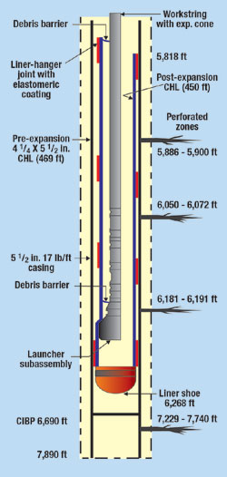
Installing four elastomer hanger joints, using one between each zone, isolated the three perforated zones. Isolation of each perforated zone allows for later re-completion of one or more of the zones, if desired. Following successful installation of the expandable CHL, the well was fraced down the 5-1/2-in. casing with the liner installed opposite the upper completion. A maximum frac pressure of 3,637 psi at 65 bpm successfully stimulated the lower zone. The resulting production increased to 1.5 MMcfd from 100 Mcfd, an increase of 1,500%. Case history 2. The W. A. Askey Well 1 was drilled in 1989 to an 8,010-ft TD and completed with 5-1/2-in., 17.0 lb/ft, K-55 casing. After perforating from 7,514 to 7,740 ft and acidizing, the Barnett Shale was abandoned. The well was initially completed in three Atoka Conglomerates from 5,886 to 5,900 ft; 6,050 to 6,072 ft and 6,181 to 6,191 ft; in the Boonsville (Bend Conglomerate, Gas) field. Like the William Miller well, the workover strategy for the Barnett Shale consisted of covering the higher zones to stimulate and produce deeper zones in the wellbore, 7,229 to 7,740 ft. The CHL solution was selected to address expected high frac pressures / volumes. The CHL installed was 469 ft long before expansion, Fig. 7. It was 4-1/4-in. diameter (10.7 lb/ft) that was expanded and "clad" inside the 5-1/2-in. well casing. The expansion increased ID 14.3% and decreased length 4% (post-expansion length 450 ft). The resulting mechanical properties of the expanded casing included: internal yield, 6,960 psi; collapse, 3,940 psi; and ID, 4.287 in.
Again, installing four elastomer hanger joints, one in between each zone, isolated the three perforated zones. This isolation allows for later re-completion of one or more of the zones, if desired. Following successful CHL installation, the Barnett Shale formation was successfully fracture stimulated down the 5-1/2-in. production casing. A frac pressure of 3,890 psi at 58 bpm successfully treated the lower zone. A second frac stimulation was performed on the previously untested Upper Barnett Shale from 7,229 to 7,317 ft with a maximum treating pressure of 3,943 psi at 55 bpm. Following the stimulations, commingled Upper and Lower Barnett Shale production was established at an average 650 Mcfd. Application evaluation. Expandable products are not a panacea for all operational problems involving downhole tubulars, and little more than a novelty if cost-effective applications are not the end result. The economics of SET products must work for the long-term benefit of the operator. Careful consideration must be given to the economics when evaluating candidates for well remediation. Factors such as well replacement cost, lost production, indirect costs such as site remediation, and direct costs of the intervention, all must be weighed against the benefit of extending well life. Situations that lend themselves to economic feasibility include: 1) larger hole size and/or greater mechanical properties for additional production and/or production enhancement; 2) marginal wells that develop leaks – expandable products are a viable alternative when other remedial techniques such as cement squeezes fail and production does not justify running a full steel liner; and 3) isolating zones in an openhole completion to reduce production of water. Rather than leave behind recoverable reserves when the oil/water ratio becomes unfavorable, expandable products can be used in conjunction with cement to isolate viable producing intervals from those producing water. Acknowledgment This article was prepared from the paper, "Well remediation using expandable cased-hole liners – summary of case histories," written by the authors and presented at the Southwestern Petroleum Short Course, Lubbock, Texas, April 24 – 25, 2002 Literature Cited 1 Filippov, A., et al., "Expandable tubular solutions," paper SPE 56500, presented at the 1999 SPE Annual Technical Conference and Exhibition, Houston, October 3 – 6, 1999. 2 Lohoefer, C. L, et al., "Expandable liner hanger provides cost-effective alternative solution," paper IADC/SPE 59151, 2000 IADC Drilling Conference, New Orleans, Louisiana, February 2000. 3 Haut, R. C. and Q. Sharif, "Meeting economic challenges of deepwater drilling with expandable-tubular technology," 1999 Deep Offshore Technology International Conference and Exhibition, Stavanger, Norway, October 1999. 4 Brock, J. et al., "An expanded horizon," Harts E&P, February 2000, pp. 115 – 118. 5 Mack, R. D., T. McCoy and L. Ring, "How in-situ expansion affects casing and tubing properties," World Oil, July 1999, pp. 69 – 71. 6 Mack, R., et al., "In-situ expansion of casing and tubing – Effect on mechanical properties and resistance to sulfide stress cracking," paper 00164, Corrosion 2000, March 2000.
|
||||||||||||||||||||||||||||||||||
- Coiled tubing drilling’s role in the energy transition (March 2024)
- Using data to create new completion efficiencies (February 2024)
- Digital tool kit enhances real-time decision-making to improve drilling efficiency and performance (February 2024)
- E&P outside the U.S. maintains a disciplined pace (February 2024)
- Prices and governmental policies combine to stymie Canadian upstream growth (February 2024)
- U.S. operators reduce activity as crude prices plunge (February 2024)

