Technology at Work: Important basic facts regarding riser tension and mud weight
TECHNOLOGY AT WORKImportant basic facts regarding riser tension and mud weightJack Bayless, Consultant, West Hou, Inc., Houston, Texas
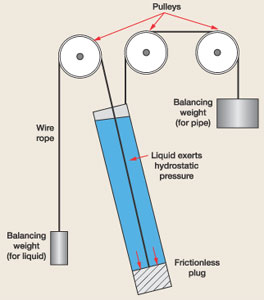
This is important because correct application of hydrostatic pressure must be done as a basis of all drilling riser analyses, i.e., the basics must be correct, or all of the riser analysis is incorrect. When it is realized that top tension to support horizontal components of mud weight is transmitted to the flex joint, then correct analysis can be done. When the bending moments on the stack are correct, then correct risk analysis can be done, and operational variables can be tightened to result in safer deepwater drilling. Basic hydrostatics. Fig. 1 illustrates that pipe weight and liquid weight are independent. Only unbalanced forces are shown on the schematic scales (weighing devices). Thus, a riser pipe at an angle cannot lift or support liquid in a vertical direction, except for a very minor part, which amounts to (1 – cosine) of the angle. If the pipe angle is 10°, then (1 – cosine 10) is 1.5%, and 98.5% of the mud weight is supported by unbalanced projections (diameter reductions such as casing hangers in the subsea wellhead) and the bottom of the hole.
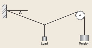
A major oil company’s drilling manual recognizes this fact and makes the point that mud weight does not affect actual riser tension; thus, tension at any point along the riser will be the same, regardless of internal mud weight. It notes, further, that because of this, a riser could have a large actual tension at the emergency disconnect above the BOP when using a heavy mud, and both of these factors should be recognized and corrected before disconnecting the riser. How does tension work. From Shortley and Williams (Basic Physics, 1950), we note that tension applied to a horizontal string will support a perpendicular load/2 according to the sine of the angle created by that load, Fig. 2. Note that the tension supports half the load because each end of the string shares 50% of that load – this becomes obvious as the angle approaches 90°. For example, calculate the tension required to support 10 lb of weight if Angle A is 10°, and the pulley is 10 ft from the wall. Answer: 10/(sine 10)/2 = 28.8 lb. For 1°, the answer is 286 lb. This example illustrates the fact that large tensions are required to support small perpendicular loads, especially at low angles.
Now turn the diagram 90° so that the wall is at the bottom and a perpendicular load is horizontal. This represents a riser system where an internally generated horizontal load is supported by tension in the riser wall. The horizontal component of the weight of mud in a riser tube can be approximated by the sine of the riser angle times the summation of mud weight (others may prefer to use equations presented in API 16Q). Thus, if the riser has a net mud weight of 1 million lb, and the riser is at 4° at the flex joint, the horizontal load is about 70,000 lb. To support this horizontal load, the riser must be tensioned by 70,000/(sine 4) = 1,000,000 lb. Thus, the tension approximates the mud weight, not because it is lifting the vertical component, but because the tension is supporting the horizontal component. Since basic tension equations divide the result by two, further refinements may reduce tension requirements somewhat in the real case. Why is this important. The above discussion illustrates that top tension in a riser is transmitted to the flex joint and, thus, must be considered by vector analysis to calculate the horizontal load at the flex joint, and to calculate bending moment at the BOP stack connector. In the above example, the bending moment at the connector of a 60-ft-high BOP stack is 70,000 x 60 = 4,200,000 ft-lb. The pressure capacity of the BOP can be estimated from API Technical Report 6AF. This report indicates that the pressure rating of the BOP is reduced by more than 50%. Other loads may reduce the rating even more, such as the vertical component of the riser tension, less weight of the BOP stack. Also, internal pressure of the BOP is higher by the amount of the new mud weight at the water depth times the hydrostatic gradient. In summary, what must be considered?
Further, wave action and currents at the top of the
riser may generate additional tension requirements, but top tension already applied for high mud weights may
be sufficient. And remember, riser analysis must be based on physical reality, not fiction.
|


