Technology at Work: 3-D modeling decreases CAD time for drilling system design
TECHNOLOGY AT WORK3-D modeling decreases CAD time for drilling system design
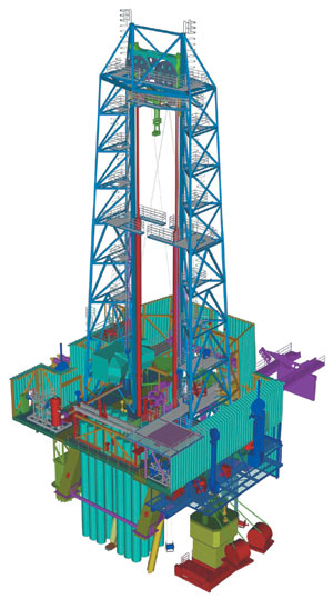
When changes to the design were needed, they were done on the 3-D model instead of modifying individual drawings. After the design was finalized, fabrication drawings were generated automatically. Time saved was the result of several factors, such as the ease of making changes on the model vs. revising drawings by hand, and the speed of generating isometrics automatically. The lack of clashes was the result of the superior visualization 3-D modeling provides, as well as the ability to include components from all design disciplines into one model. Aker’s RamRig concept for drilling / workover packages can be used for both fixed and floating installations, Fig. 1. It is available as single, double or triple stand rigs, with capacities from 150 to 1,000 t. Hoisting and lowering is done by two cylinders instead of the conventional drawworks and derrick. Hoist lines are fixed length, parallel lines with one end anchored at the drill floor, the other at the top drive. The lines are run over the yoke sheaves, thereby transforming the push from the rams to upward lifting force to the top drive. Main benefits are lower weight and cost, greater efficiency, and improved safety over conventional packages.
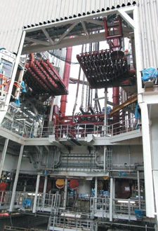
Tight space. The Snorre B project involved installation of a RamRig system on an offshore platform in the North Sea. This project was a joint venture between Aker Maritime and Kvaerner Oil & Gas. It involved design / construction of a semisubmersible drilling / production platform for Norsk Hydro ASA. In addition to the rig supplied by Maritime Hydraulics, the platform features combined cycle power generation units (gas turbines and steam) and an undersea power cable linked to Snorre A for import and export of excess power. Snorre B exports oil to Statfjord B and gas to Snorre A. The total RamRig weight was 1,400 mt, with dimensions of 20 m x 20 m (66 ft x 66 ft). This was a very small area in which to fit a great deal of equipment, including manifolds, cabins and tensioning system, as well as all the mud and hydraulic piping. A RamRig uses high-pressure hydraulics to lift the drill string. There is very high flow on those lines, many of which are 8 in. in diameter. All piping for the drill system had to fit within the rigs dimensions. Height was limited by the low drill floor and the BOP height, leaving less than 5 m of effective height, Fig. 2.
The Snorre B was Maritime Hydraulic’s first use of advanced 3-D modeling. In previous projects, engineers had used 2-D AutoCAD to place equipment, pipes, structural steel, and so on. Routing pipe this way was particularly difficult in 2-D because it required piping engineers to imagine elevations and indicate with elbow symbols whether a pipe went up or down. They had to maintain consistency with other drawings as they worked, visualizing the Z component of those other views as well. Each 2-D drawing was actually an exercise in piping design. Another drawback to working in 2-D was the difficulty of detecting interferences when only two dimensions were visible. This was true within a single discipline, such as piping. Designers used plan, section and elevation views to try to spot clashes, but if pipe heights on two drawings did not match perfectly, it was possible for an interference to go unnoticed. It was also difficult to detect interferences between different disciplines because they typically did not share a common base like a 3-D model. A third drawback to the previous 2-D method was that once a design was done, it was necessary to produce, from scratch, all of the isometrics and other drawings needed for fabrication. A typical project required hundreds of isometrics, and this could be one of the most time-consuming aspects of a project. Finally, when changes to the design were needed, it was necessary to make modifications on the drawings. This was time-consuming since one change could affect many drawings. It also compromised accuracy because it was possible to overlook a drawing that should have been changed. These drawbacks, combined with the tight space limitations of the Snorre B project, led Maritime to consider upgrading to 3-D plant design software. The search was limited to programs that ran on top of AutoCAD since this program was so widely used, both within the company and in the oil / gas industry. Maritime chose AutoPLANT because – in addition to being an AutoCAD add-on program and providing full 3-D modeling capabilities – it included modules for specific design disciplines. This would make it possible to exchange 3-D models between disciplines and automate more of the design process. For example, rather than sketching crude representations of mechanical equipment, a structural engineer could place existing equipment models into his design. Maritime purchased five sets of AutoPLANT Piping, one set of AutoPLANT Equipment, two sets of the intelligent piping and instrumentation diagram (AutoPLANT P&ID) application, five sets of the AutoPLANT Structural steel design module, and four sets of AutoPLANT Isometrics, which produces isometric drawings automatically from the 3-D model. The company also purchased the necessary import / export utilities from Regis for transferring AutoPLANT data to AutoPIPE and ISOGEN. The software was purchased from Mandal Engineering Co., which also provided implementation support. Team design. Fifty engineers worked on the Snorre B project, with about 20 working concurrently in AutoPLANT. Some had previous experience working in 3-D, but the company also provided two- and three-day training sessions to familiarize everyone with the new software. On this project, the mechanical, piping and structural engineers worked in AutoPLANT, while those in the electrical, architectural, and HVAC disciplines used plain 3-D AutoCAD. Mechanical engineers used the Equipment module to model and place pumps, tanks and other vessels in the model. This module automated much of their work by providing a library of parametrically defined components. With the library, an engineer simply entered a few values representing the equipment specs, and the software drew the model. Piping engineers used the Piping module to route the pipe. To do this, they drew lines indicating where pipes should be placed, as they would in 2-D. But rather than simply having geometric representations, the digital model of each pipe was actually an object containing additional information from the database, such as performance and material specs. And because the engineers were working in 3-D, they were able to include the Z dimension in the model – routing a pipe 10 m horizontally, for example, then up 5 m, and then horizontally another 10 m. Another benefit of building a 3-D model of the piping was that entire lines were visible, compared to drawings that showed only pipes in a certain section of the rig. When an engineer finished routing a line, he could see the impact of his work immediately, rather than flipping through 2-D drawings and trying to follow it. All these features helped speed the process of routing pipes; but what made this approach significantly faster than 2-D was that, with the 3-D model, piping was designed only once, instead of over and over again on each individual drawing. Structural engineers originally used plain AutoCAD to design the structural framework of the Snorre B rig. Then they realized how easy it would be to convert their work to 3-D using the Structural module. This application provides the functionality needed for: placing 3-D structural steel, including drawing setup and creation; 3-D grid placement; steel placement and database management; steel editing and display options; steel annotation; and access way (stairs, ladders, platforms and handrails) placement. Similar to the Equipment module, Structural Modeler has a library of standard shapes. When an engineer wants to run a beam from one location to another, he simply chooses beam shape and indicates desired location. The software draws the model of the beam automatically. On this project, engineers simply selected lines from the AutoCAD drawings, indicated in a dialog box the type of members they were, and the software drew the 3-D shape. Although electrical, architectural and HVAC engineers used plain AutoCAD, everyone’s work contributed to creation of the 3-D model, since geometry created in AutoCAD could be referenced into the 3-D model by means of the AutoCAD "x-ref" feature. This made it possible for engineers to reference each other’s models and be aware of other design changes that affected their work – this was one way that the company was able to eliminate clashes. But Maritime also used AutoPLANT’s Explorer module after the entire design was complete to perform a thorough evaluation for clashes. The software recognized all one-, two- and three-dimensional AutoCAD entities for viewing and interference detection, including lines, polylines, 2-D surfaces, meshes, 3-D faces, ACIS solids, and blocks, as well as any custom 3-D objects created with AutoPLANT. Some interferences were found during this operation. The changes necessary to fix those problems, as well as others, perhaps requested by the customer, went much faster compared to those done in 2-D. This time, changes were made by modifying the 3-D model. It was not necessary to alter any individual drawings because drawings are associative to the model and are updated automatically when the model changes. This was much faster than going back and modifying many drawings to reflect a change; it was also more accurate. When the team worked strictly with drawings, it was possible to miss some that were affected by a change. That did not happen, because drawings were "spun off" from the model. Isometrics were the only form of piping drawing used on this project. They were not produced by hand, but generated automatically from the model. Engineers simply selected the views they wanted and commanded the software’s Isometrics module to create the drawings. Only a few minutes were spent on each drawing, doing minor touchup such as adding a special number required by the customer. All the other information was automatically extracted from the model. The drawings had elevations and dimensions tagged and located, for example, and materials for purchasing were automatically derived from the database. Drawings produced in this manner required minimal checking because the software ensured that they were consistent with the 3-D model. The RamRig was installed on the Snorre B platform in
May 2000. Though it was clear to Maritime that working in 3-D significantly reduced design / documentation
time, the company was even more pleased with the new approach when the rig was assembled and there were no
clashes.
|
- Applying ultra-deep LWD resistivity technology successfully in a SAGD operation (May 2019)
- Adoption of wireless intelligent completions advances (May 2019)
- Majors double down as takeaway crunch eases (April 2019)
- What’s new in well logging and formation evaluation (April 2019)
- Qualification of a 20,000-psi subsea BOP: A collaborative approach (February 2019)
- ConocoPhillips’ Greg Leveille sees rapid trajectory of technical advancement continuing (February 2019)


