Technology at work: E&P Case Study examples, other industry technology advances
TECHNOLOGY AT WORKE&P Case Study examples, other industry technology advances
In addition to the special PTTC-contributed report, two additional articles come from international industry sources, including:
Addressing the margin while preparing for tomorrowE. Lance Cole, National Project Manager, Petroleum Technology Transfer Council (PTTC) By the time this is published, the Petroleum Technology Transfer Council (PTTC) will have organized nearly 20 survival-oriented workshops around the country since its Industry Crisis Action Plan was launched in December. Operators attending these workshops are aware that no magical technology solutions exist for today’s crisis. But they have been interested in hearing practical, low-cost information like that summarized below. The cost side. It is important to know "true" costs. In large multiwell projects, knowing when to rework wells is critical. By knowing true well-operating costs and the cost of fixing various field problems, some companies can decide within a matter of minutes whether to fix wells that go down or leave them shut down. These costs should be broken down into meaningful categories for individual wells, which include both direct lifting costs and total costs. This level of analysis allows operators to prioritize which cost-reduction efforts have the most impact. Reducing power costs. Improving efficiencies, such as matching electric motor size and pumping cycle to the volume of fluid to be pumped, can reduce the basic energy charge. Additional savings are possible when demand charges are 50% or more of the total bill. Power factor — the ratio of real power needed to get the job done to total power supplied — is another consideration. If the power factor is less than 95%, operations may be more cost effective with line capacitors.Switching to interruptible service is one option for lowering electricity cost. Controlling when power is used is another factor, e.g., consider both off-peak and seasonal discounts. Using timers and pumping during off-peak periods, an Illinois basin operator reduced power consumption by 25%, and average production was not affected. Timers paid out within a month. Negotiating the royalty rate. It may be worth a try to amend the lease terms. High royalty rates hurt both royalty owner and operator, since they have the same net effect as higher operating costs. A royalty rate that slides with the price of oil reduces the likelihood of negative cash flow. When oil prices are down, the lease remains profitable longer, avoiding premature abandonment. When oil prices are up, royalty rates are higher, but the operator can generally afford to pay more royalties in this case, and still maintain profitability. The revenue side. Look for ways to reduce wellbore damage. There have been encouraging results from a treatment program focusing on removing skin damage caused by near-wellbore organic damage (wax buildup). These successful results depend on thoroughly analyzing the well history and selecting wells that have experienced a production decline that cannot be explained solely by reservoir depletion. If wax buildup is the problem, wells can be treated with solvent / dispersant combinations, followed by a 12-hr shut-in period. Experience from 70 treatments shows that, if candidate wells are properly identified, the economics are attractive for increasing production and cash flow. The well shut-in decision. There are a number of questions a producer should consider regarding reservoir conditions when wells or leases become uneconomic: 1) should individual wells or the entire lease be shut in; 2) what factors affect whether production can be recovered when the wells are brought back on line, 3) what are the risks for formation damage due to wellbore effects; 4) for injection projects, what are the long-term effects on reservoir pressurization and sweep efficiency, and 5) how can one prevent excessive damage to downhole and surface equipment? Since each situation is unique, the prioritization of these questions will differ. Protecting equipment. In some areas, the most critical concern for long-term integrity of shut-in wells is minimizing sulfate-reducing and acid-producing bacteria, and associated corrosion. One should use both corrosion inhibitor and biocide treatments, regardless of known bacteria evidence. The strategy is to distribute the proper chemicals throughout the water phase where corrosion takes place. If tubing is in the hole, it is important for the chemically treated water to contact the internal tubing surface, as well as the exterior surface and casing. Any well returned to production for a short period of time should be retreated before another shut-in. When shutting in surface equipment, the most important actions deal with flushing the system, excluding oxygen, and wrapping critical electrical and instrumentation equipment. Before reactivating, electrical systems and instrumentation should be examined, and equipment should be visually inspected. It is also important to pay attention to purging / start-up procedures. Many steps must be taken to ensure that a facility can be temporarily abandoned and quickly restarted. When facilities are shut in, the duration is uncertain, but producers must balance cost / time commitments of protective actions against potential damage. Maintaining the lease. It is important to know the actual lease terms, including the difference between state regulations and lease requirements. "Producing" oil, in a legal sense, means taking oil out of the ground, not just selling it from a storage tank. Even if a lease has been shut in, operators can take action to show intent for continued operations. For the legal concept of the "reasonably prudent" operator, it is not enough to just show production — it must be "in paying quantities." Fortunately, this does not mean that an operator has to show a profit every month, but during a reasonable period of time. The formula used to calculate "paying quantities" works out to be less than with typical operating costs. Negotiating shut-in payments may be another option. Preparing for tomorrow. In
PTTC’s survival workshops, attendees sent a strong message back — while survival is essential, there
is interest in underutilized or new technologies that are applicable in the longer term, when industry
conditions improve. There is a wealth of useful information that still needs to reach independents, and PTTC
is actively providing the technology connections.
Well diagnosis / control system cuts beam pumping costsJim McCoy, Echometer Co., Wichita Falls, Texas; and Rory Edwards and Artie Coop, Cobra Oil and Gas Corp., Wichita Falls, Texas Bottom line. By installing an improved gas separator and a timer for intermittent operation, Cobra Oil and Gas Corp. increased electrical efficiency in a beam-pumped well from 35% to 59% — cutting power costs in half — while slightly increasing production. Payout is projected to be eight months. Overview. Cobra operates five wells on the Vogtsberger lease in Texas. Vogtsberger field, originally drilled in the 1940s, comprises numerous wells completed in several different zones. Production for the well in this study, RVOGTA8, is from the Caddo formation at about 5,200 ft. In continuous operations, the well averaged 8.2 bopd and 35 bwpd, with 4 Mcfd of natural gas. In January 1999, Echometer Co. completed a well performance analysis, considering well history and diagnostic test data from acoustic liquid level measurement, dynamometer tests and a pressure buildup analysis. Results showed that the downhole gas separator system did not perform properly. Pump fillage was low, even though liquid existed above the pump, which had ample capacity for the well. To resolve the problem, Cobra installed an improved gas separator and a timer so that the beam pump system could operate intermittently — five minutes on and ten minutes off, with a full pump most of the time. Liquid level and dynamometer tests. An acoustic depth measurement indicated that the liquid level was 148 ft over the pump when the well was producing at stabilized conditions (continuous pumping). Casing pressure increased by about 0.1 psi per minute when the casing valves were closed, indicating that free gas was being produced and flowing up through the annular liquid. To determine stabilized conditions, a dynamometer test was run without shutting down the pumping unit. It showed that pump fillage was 27%, Fig. 1. Traveling and standing valve tests verified that the pump was in good condition.
Poor downhole gas separation occurs when a high liquid level is present above the pump and the pump does not fill with liquid on the upstroke. In this case, the pump was set at 5,173 ft, which is above the formation. The completion is open-hole (4-3/4 in.) below the 5-1/2-in. casing from 5,235 to 5,247 ft. The well was shut down for 10 minutes, then restarted with the same result — low pump fillage. Even after a 20-minute shut-down, poor fillage continued. As is often the case, the "poor boy" gas separator was not working effectively. Pressure buildup results. The producing bottomhole pressure was about 94 psi, but reservoir pressure was unknown. To evaluate reservoir characteristics, Cobra performed an acoustic liquid-level pressure buildup test, allowing the well to be shut in for five days. Pressure buildup tests using computerized acoustic liquid-level equipment are cost efficient, since the rods and pumps do not need to be pulled — a primary impediment to running a conventional pressure bomb. Although the well pressure did not stabilize, reservoir pressure (p*) was in excess of 1,000 psi, according to pressure buildup data. This data also showed that the well did not have skin damage, meaning re-stimulation was not necessary. Permeability also was low. Furthermore, the data showed that calculated liquid flow into the wellbore after shut-in was only about 10 bpd of liquid — considerably less than the well’s production, Fig. 2. Low liquid flow into the wellbore may indicate that some cross flow occurs in the formation. This would suggest that the pump probably should be set as low as possible in the well.
The high reservoir pressure (p*) indicated that, even after the gas interference problem was solved, very little additional production would be obtained. Therefore, before doing any further work, Cobra knew that the primary benefits of the project would come from reduced electrical and maintenance costs resulting from less run time and better equipment loading. A substantial increase in production was not expected. Servicing the well. The rods and tubing were pulled and the pump serviced. In addition, a worn pull tube was replaced. It had probably deteriorated from the continuous "pounding" of the plunger when the pump was 20% to 50% filled with liquid. The pump also had two standing valves, but only one was used when the pump was run back into the well. A tubing anchor was in the well when it was pulled, but it had a broken spring and was not run back into the well. As rerun, the tubing string consisted of 167 joints of 2-3/8-in. tubing, a seating nipple and a 2-3/8-in. collar-size gas separator that was six feet long. The bottom of the gas separator was placed 3 ft from the bottom of the well in the middle of the producing formation. A solid-state percentage timer, low voltage transformer and relay were installed in the motor panel. The goal was to reduce the amount of run time, since the 24-hour pump capacity exceeded the well’s producing capacity. The three items were purchased for $110. Post-service testing. After pumping the well overnight, the liquid level was at the seating nipple, 166.9 joints from the surface. Without shutting down the pumping unit, a dynamometer test was conducted, with the pump card showing about 30% fillage. With the liquid level at the pump and partial pump fillage occurring, the gas separator was operating efficiently. The well was shut-down for nine minutes, then restarted and run for about ten minutes. The first 36 strokes indicated full pump fillage (Fig. 3, stroke 2 of 60). The next seven strokes showed that the well was being pumped down and, from stroke 43 to the final stroke 60, pump fillage was relatively stable at around 35%. The collar-size gas separator was working effectively. A percentage timer was installed and set to run one-third of the time.
Results. Liquid level and dynamometer tests were important for diagnosing well problems, but it was necessary to review the downhole equipment to get the full picture. The pressure buildup analysis helped determine whether the well needed to be re-stimulated, and what production level to expect. The beam pump now operates five minutes on and ten minutes off, with a full pump until near the end of the on cycle. While there has been only a slight increase in oil, water and natural gas production, the overall electrical efficiency was improved from 35% to 59%. Power costs are approximately $108 per month, about half of the earlier level ($203 per month). With smoother operation and less stress on equipment, lower maintenance costs also are anticipated. Payout for the total well work is expected after about eight months.
The authorsJames McCoy is president of Echometer Co., where he has been involved with research and development, product testing of the computerized Well Analyzer and teaching seminars. McCoy purchased the company in 1962. Contact: 5001 Ditto Lane, Wichita Falls, TX 76302; tel 940-767-4334; fax 940-723-7507; e-mail jim@echometer.com. Rory Edwards is a production supervisor for Cobra Oil and Gas Corp., where he has been employed for the past 61D2 years. Edwards earned a BS in geology from Midwestern State University. Contact: PO Box 8206, Wichita Falls, TX 76307; tel 940-716-5100; fax 940-716-5180. Artie Coop is field foreman over the Vogtsberger lease. He has been employed by Cobra Oil and Gas Corp. for 20 years. Contact: Route 2, Box 39, Wichita Falls, TX 76301; tel 940-723-9626.
Controlling water channeling with low-cost plugging optionWaylan C. Martin, Landra Co. and Martin Water Laboratories, Inc., Monahans, Texas; and Robert M. Orr, Owner-Operator, Monahans, Texas Bottom line. Using sodium hydroxide to cause selective deposition can decrease high water production and, with diversion of injection water, lead to a modest production increase. A $6,000 treatment, intended for mature marginal waterflood operations, paid out in seven months. Overview. Water channeling can be a serious problem in injection projects, particularly with attendant low oil recovery and high operating costs from cycling injected water. Several different treatments, most commonly gel polymer, have been used to control water channeling with varying degrees of success. The new "Water Flow Obstruction Process" causes scale to selectively form in situ in the water channel. Since the process helps scale or plug offending channels, it is intended as a last resort for mature injection operations — those situations in which there is not much to lose. Selective deposition occurs through injecting a strong alkaline compound — preceded and followed by fresh water pads — followed by injecting field brine. As the treatment moves down the water channel, a mild alkaline influence is left behind, which is picked up by the subsequent injection water. This process causes a calcium carbonate scale to form. Scaling continues as the water moves away, until the channel is obstructed some distance from the injection well, diverting subsequent injection water from the channel. Working with operator Robert Orr, the Landra Co. treated an injection / disposal well in a mature waterflood where severe water channeling was evident. The treatment selectively plugged the water channel and extended the economic life of this mature injector-producer pair. The significant reduction in produced water in the offset well confirmed this result, along with indications of response in area wells and positive injection rate and pressure data. Additional experimental work and field data show that the process should be tailored to individual situations, which can be done. Controlling water channeling. The wells are in a mature Yates sandstone waterflood in Winkler County, Texas, developed on 10-acre spacing. The mature Crenshaw 1 well has produced 112,000 bbl of waterflood oil. Prior to the treatment of Clapp 1, the offset injection well, Crenshaw 1 produced 5.5 bopd and just over 400 bwpd. The stabilized injection rate in Clapp 1 was 570 bwpd at 560 psi. With the high water production, operations were considered marginal. Other offsets included an unaffected producing well (south), a plugged and abandoned well (west) and a well that was experiencing breakthrough from Clapp 1 (north). It also was found that Crenshaw 1 was affected only slightly, if at all, from other disposal / injection wells. Since there was not a uniform injection pattern area, the operator did not expect much incremental oil recovery from the treatment — it was planned primarily for water control. Treatment of Clapp 1. The Clapp 1 well was treated with a 100-bbl freshwater pad and 200 bbl of 20% sodium hydroxide, followed by a 100-bbl freshwater pad, all injected at 570 bpd. Following treatment, the well was shut in until injection wellhead pressure dropped to zero. This allowed backflow of the water and chemical into the more permeable intervals. Injection was initiated at a low rate and increased to 520 bpd at 820 psi over a two-week period. The rate and pressure varied before stabilizing at 620 bpd and 840 psi after six weeks, where it remained for three years. Before, during and after the treatment, Crenshaw 1 was kept completely pumped off to allow all of the water and chemicals to selectively move through and react in the water channel. Treatment effectiveness. Injection pressures in Clapp 1 remained steady at over 800 psi, demonstrating that the selective plug was holding. Water production in Crenshaw 1 was cut in half within two to three months, from just over 400 to 200 bwpd. Fig. 1 shows injection rates and pressures in Clapp 1 and water production from Crenshaw 1.
Water production continued to decrease, falling to 100 bwpd after five months, where it remained through 15 months. While water production fell, oil production increased from 5.5 to 6.9 bopd two years after the treatment. Considering its low cost, the treatment was considered economical, paying out in seven months. Additional experience. Differences in the involved waters also need to be considered in the treatment process. Brines with high magnesium concentrations present unique challenges, since they tend to neutralize the injected alkaline slug. Operators in another field application helped to evaluate selective deposition in waters with high magnesium content (3,000 to 4,000 mg/l). In this instance, the objective was to selectively plug the connate water zone. The high calcium concentration actually aided the selective plugging process. The treatment was applied in the same way as was used on the Clapp 1 well, with one ton of hydroxide equivalent per 100 mg/l. The increased injection pressures and reduced water production rates in the producing well demonstrated success, although the selective plugging took time to develop, Fig. 2. When greatly increased pad volumes were used, the fresh water, which contained 142 mg/l calcium, scaled the channel prematurely, Fig. 3.
Scaling not a problem. The tests clearly demonstrated that when an obstruction forms in the water channel, any excessive alkaline chemical present is directly in front of the obstruction and will permanently stall in this position, preventing excessive chemicals from reaching the well. Scaling in the producing wells has not been a problem. During the 3-1/2 years after the treatment in Clapp 1, no alkaline influence reached Crenshaw 1. Field observations, results. Field data showed that the selective deposition process can be effective in plugging water channels. Additional data indicate the process can be tailored for brines having higher magnesium concentrations. Although the process has not been widely field-tested, it has been successful in limited applications. Results to date have confirmed its low-cost potential for solving water channeling problems, making it a viable last resort alternative for selected mature injection operations.
The authorsWaylan Martin, in addition to his affiliation with the Landra Co., is president and CEO of Martin Water Laboratories, Inc., an oil field water analytical laboratory that he has owned since 1964. He earned a BS in microbiology and chemistry from Baylor University and an MA in microbiology and chemistry from the University of Texas at Austin. Contact: Landra Co., P.O. Box 1687, Monahans, TX 79756; tel 915-943-5420; martinl@ultravision.net. Robert M. Orr has been an owner-operator and consultant since 1971 and is vice president of engineering operations for Transpetco Engineering. He previously was chief engineer for George L. Buckles Co., where he oversaw more than 30 waterfloods. Orr earned a BS in petroleum engineering from the University of Texas at Austin and is past president of the Permian Basin Petroleum Association. Contact: P.O. Box 176, Monahans, TX 79756; tel 915-943-3251.
Improving sweep with injection well polymer gel treatmentDavid F. Bishop, True Oil Co., Casper, Wyo., and Julie Smith, TIORCO Inc., Englewood, Colo. Bottom line. A large gel treatment in a sandstone injector improves waterflood sweep, recovering an additional 80,000 bbl of oil to date at an incremental cost of $1.00 per bbl. Overview. Polymers long have been used to combat mobility ratio and reservoir heterogeneity in Tyler sandstone waterfloods in northeast Montana. Initial water injection in Breed Creek Unit’s Well 43-10 caused an oil response starting six months later. The water-to-oil ratio (WOR) with the initial response was 0.4. Eight months later, water rapidly increased, indicating injection water breakthrough to wells in the south end of the field. To remedy the situation, a large MARCIT gel treatment was placed in the injection well to restrict flow of water in high permeability channels deep within the formation. The response in offset producing wells was noticeable six months after the gel treatment. Reservoir characteristics. Northeast Montana’s heterogeneous Tyler sandstone, Pennsylvanian in age, has some vertical permeability and little or no natural fracturing. The Breed Creek Unit produces at an average depth of 4,875 ft. Producing sands are erosional channel sands deposited in paleo-river channels, with trapping both structurally and stratigraphically controlled. The paleo-river deposits alternate with shale and limestone, and are bounded on the top and bottom with unconformities. The Tyler pay consists of medium- to coarse-grained sandstone that is fairly well sorted and slightly finer toward the top. Conglomerates are sometimes present at the base of the interval. While there is limited core data, permeability varies significantly — ranging from 1 md to 3.9 D. This reservoir heterogeneity can lead to inefficiencies in waterflooding. Porosity at Breed Creek averages 14.3%, with connate water saturation averaging 34% of the pore volume. Original oil in place (OOIP) in the C sand is 7.45 million bbl. On primary, 22.1% of OOIP was recovered by solution gas drive. Expected additional secondary recovery by waterflood is 10.5% of OOIP, for a total of 32.6%. This translates to a secondary:primary ratio of 0.48. The bottomhole oil viscosity at 173°F was 1.9 cp, leading to a reasonable mobility ratio for waterflooding. The expected waterflood recovery was mainly limited by the reservoir’s heterogeneity. Fig. 1 shows a project map. Wells are on approximately 40-acre spacing along the channel, with no uniform pattern.
Rapid waterflood response. In May 1994, a waterflood was started in Well 43-10 in the south end of the field. Fig. 2 shows a time-rate curve for the combination of the three nearest offset producing wells. Oil response, which began after six months of injection, was combined with connate water so that the WOR averaged about 0.4. Eight months later, water began to increase rapidly, indicating injection water breakthrough to the producing wells. Comparing the WOR to cumulative oil recovery curve (Fig. 3), the moveable pore volume in the most permeable channel was estimated at 60,000 bbl. This estimate was based on cumulative oil production from the first response to waterflooding to the first water breakthrough. Injection well polymer gel treatments. When properly applied in appropriate reservoir conditions, polymer gel treatments are effective for reducing high water production and improving oil recovery. The gels move into highly permeable, water-saturated zones and severely reduce permeability to water so that oil can be produced from tighter rock. These gels can be applied to both injection and producing wells. For injection wells, the goal is to improve volumetric sweep so that oil recovery at offset wells increases and water production decreases. In the Breed Creek Unit, True Oil applied an injection well treatment using a medium molecular weight, water-soluble, partially hydrolyzed polyacrylamide and chromium acetate crosslinker, based on MARCIT technology, which was developed by Marathon Oil Co. Early in waterfloods, gel treatments have a stronger impact on pattern performance when applied from injection wells, as opposed to producing wells. Other options for controlling water channeling include cementing off the offending zone or treating it with other water shut-off agents, such as resins or other gels. These options are effective only in close proximity to the injection well, since the chemicals or materials cannot be placed deep in the formation. In the case of Breed Creek, where the Tyler formation has some vertical permeability, a near-wellbore treatment would cause injection water to leave the wellbore from the proper zone, then cross-flow back into the highly permeable channels near the injection well. The resulting decrease in water production would be minimal, as would the incremental oil response. On the other hand, MARCIT gels can be placed deep in the formation, allowing a maximum impact on pattern performance. Treating the injection well. A large gel treatment was placed in the 43-10 injection well in May 1996. The gel volume of 18,000 bbl was about 30% of the moveable pore volume in the channel. Injection well response is the first indicator of gel effectiveness. Prior to the treatment, Well 43-10 took injection on a vacuum. Immediately following gel treatment, surface pressures ranged from 500 to 700 psi at the pretreatment injection rate. This pressure held for three months, then dropped to 200 to 500 psi, where it remains. Pressure buildup from the injection well shows that the gel is forcing subsequent flood water into tighter, unswept rock. Production response. Six months after treatment, a response was seen at the offset producing wells, and was sustained for the next 26 months. Fig. 2 shows a decrease in the oil decline rate and an end to water production increases. Fig. 3 plots WOR versus cumulative oil recovery and clearly shows a breaking over of the increasing WOR trend. These changes indicate that oil was moving from 43-10 (previously unswept rock with higher oil saturations) toward the three offset producers following the gel treatment.
Considering WOR trends through September 1998, incremental oil recovery was 80,000 bbl. This was estimated by extrapolating WOR before and after gel treatment to an economic limit of 20. The gel polymer cost for this project is $1.00 per incremental bbl of oil. The incremental oil production amounts to 1% of OOIP field-wide, or 2% to 4% of OOIP in the southern area of the field affected by the gel. Factors contributing to success. The reservoir at the south end is fairly well confined, making definition of the problem and response to the gel treatment more straightforward. Excellent operating and record-keeping by the operator also have been essential in verifying response to the gel treatment. In addition, the project area was maintained with as few changes as possible following the gel treatment. Finally, the timely placement of the gel resulted in a stronger, more defined treatment response. With less water-saturated rock between the injector and offset wells, more incremental oil was recovered when gel was placed earlier in the life of the waterflood. Lessons learned. Generally, successful injection well gel treatments occur when several factors apply. First, channeling from the injector to one or more producing wells should exist. Second, producing WORs need to be high or increasing, with production still economic and significant quantities of recoverable oil in the pattern area. Third, the injection well must have the capacity to accept a gel treatment, build pressure and maintain a desired injection rate following the treatment. Finally, and perhaps most important, the gel volume should be large relative to the estimated volume of the channel, or to the permeability of the rock conducting the water. Results of injection well gel treatments are typically evaluated over a one- to two-year period. During this time, it is important to avoid changing any pattern that could affect WOR or production rates. By maintaining a consistent pattern — as was done at Breed Creek — results of the gel treatment are definable.
The authorsDavid Bishop has been superintendent at True Oil since 1977, where he is in charge of the company’s producing operations. Before joining True Oil, he worked for Conoco in engineering and operations. A registered professional engineer in Montana and Wyoming, he earned a BS in petroleum engineering from the University of Wyoming. Contact: PO Drawer 2360, Casper, WY 82602; tel 307-237-9301; fax 307-266-0252. Julie Smith began her career in 1978, joining TIORCO as an IOR lab technician. She is currently the company’s department manager for chemical engineering and applied chemical IOR technology. The author of 15 technical papers, Smith earned a BS in chemical engineering from the Colorado School of Mines. Contact: 1795 West Warren Avenue, Englewood, CO 80110; tel 303-935-0046; fax 303-935-1514.
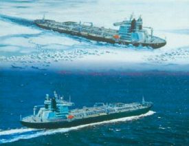
Better icebreakers: New opportunities for Arctic oilKvaerner Masa-Yards Inc. (KMY) looks at Arctic navigation and icebreakers as one of its core business areas. The company’s Helsinki shipyard has built more than 60% of the world’s icebreakers, and the company’s Arctic Technology Centre (MARC) in Helsinki, the only research center of its type run by a private company, plays an important role in helping it develop new technologies. Many shipowners, international oil companies and research institutes rely on these technologies, among them the Krylov Shipbuilding Research Institute in St. Petersburg, which has bought equipment and methodology from MARC for its ice model tests. Recent clients include oil companies like Exxon, Shell, Mobil, Conoco, Statoil, Gazprom, Fortum and China’s Bohai Oil. At the beginning of the 1990s, KMY initiated a program to develop new competitive solutions for the Arctic tanker trade. As part of this, scientific expeditions have been mounted regularly in cooperation with Russian partner organizations. During the winter of 1997–1998, expeditions were made to the Pechora Sea, the Gulf of Ob and the waters around Sakhalin. New information was also obtained from the North Caspian, where close to one-meter ice thicknesses were measured. This year, "hundred-year" conditions have been recorded both in the Caspian and Pechora Seas. A new propulsion system. Another important project has been development of a new azimuthing electric propulsion system. The first prototype of this system, today marketed under the Azipod brand name, was built and installed in 1990. The first production unit, rated at 11.4 MW, was installed in 1993 on the Uikku, a 16,000-dwt Finnish tanker. This was followed two years later by a second unit in the sister ship, the Lunni. To date, these two ships have put in some 40,000 hr of successful operation. And the system has already been installed on two new icebreakers. The newest of these, the Botnica, a multipurpose icebreaker / offshore construction vessel delivered to the Finnish Maritime Administration, is fitted with twin 5-MW units.
The double-acting ship. Combining the advantages of electric propulsion with superb maneuverability and valuable savings in machinery space, Kvaerner’s podded drive concept represents a major step forward in ship propulsion — whether in the ice packs of the North-East Passage or the balmy waters of the Caribbean. It has also provided the inspiration for a totally new concept — the double-acting ship. Baltic icebreakers typically have a power distribution potential, fore and aft, ranging between 40% and 75% of the total power in bow propellers. Comprehensive full-scale tests over the years have shown that ice resistance decreases as power is increased to the bow propellers. Minimum ice resistance can be achieved when 100% of an icebreaker’s power is directed to its bow propellers. Against this background, an Azipod-equipped ship could be expected to offer very good performance when running astern in ice. Full-scale tests in ice on the first ships bore this out, and showed a potential to cut ice resistance by as much as 50% when running astern. The astonishing performance of the Lunni in severe ice conditions clearly showed that it is possible, and even desirable from a performance point of view, to design an Azipod ship to run astern on a regular basis. Different mode of operation. Traditionally, all ships, and particularly conventional Arctic ships intended for independent operation, are sums of compromises. When designing a bow, the designer has always had to balance the needs of open-water and ice operation requirements. If the focus is on good icebreaking capability, the result will inevitably be poor open-water performance and bad seakeeping properties, and vice versa. The emergence of the Azipod concept changed all that. It gives the designer a unique possibility to design the bow of the ship to be good in open water, and the stern to break the ice. The result — a "double-acting" ship. The bow design of the double-acting tanker (DAT) concept incorporated experience built up with conventional vessels, and it is an efficient, ice-strengthened, open-water bow. This gives open-water performance that is some 10 to 15% better than that of a conventional icebreaking bow. The stern is designed to break the ice. Utilizing the full potential of the bow propeller effect, the vessel can attain the required icebreaking capability using only 60 to 70% of the power required by the best conventional icebreaking hull forms. In a DAT design, the mode of operation is completely different from normal penetration based on ramming. A DAT vessel enters a ridge field at slow or moderate speed and lets its pulling propeller chew up the ridge and slowly pull the vessel through. Less engine power, lower cost. Due to the high icebreaking performance of the DAT concept, costs are lower than those of conventional designs, mainly due to the need for less engine power. The flexibility of the machinery also offers a number of benefits. Operating costs will also be lower, as the efficiency of the vessel in open water is higher than that of a conventional design. The company has signed a letter of intent with RAO Gazprom and Fortum Shipping for the construction of a 90,000-dwt DAT tanker for trade in the Baltic and Pechora Seas. The vessel is expected to enter Arctic service in 2003. The first two icebreaking supply vessels for the Caspian Sea incorporating the new concept were recently delivered. Named Arcticaborg and Antarcticaborg, these two vessels, ordered by Wagenborg Shipping of the Netherlands for the OKIOC consortium led by Shell, feature two propeller units totaling 3 MW. This will give them the capability of navigating in ice of up to one meter in thickness in continuous mode, and reaching a platform stern-first through ice formations around a drilling platform, a performance never before experienced. The concept has been developed further by Masa-Yards in some related applications. The oblique escort tugboat is able to break a channel up to 40-m wide for big tankers, and the bow-propeller-only-driven seismic vessel with an air bubbling arrangement will make seismic work in icy waters possible, thus extending the operational season several months. Navigating the Arctic. To build up its hands-on experience in Arctic navigation, KMY acquired a 50% stake in Uikku and Lunni in 1993. Both tankers now have five years of successful experience in the Arctic trade. In 1997, Uikku made maritime history as the first foreign-flag merchant vessel to sail along the entire North-East Passage, taking only 12 days from Provideniya to Murmansk. Last year, the vessel carried out an experimental midwinter demonstration
voyage to the Gulf of Ob as part of the ARCDEV project, partly funded by the European Commission, and
effectively showed that year-round navigation in Arctic waters is both technically and economically viable.
Despite the worst ice conditions in the Pechora and Kara Seas in 30 years, the tanker achieved an average
speed of 9 kt. Last December, it visited the remote port of Pevek on the Chukhotka Peninsula later than any
other ship.
Wellhead / horizontal trees for Val D’Agri fieldMario Schiatti, Mechanical Engineer, Technical Director for wellheads, valves and control systems, Breda Energia Sesto Industria S.p.A., Milano, Italy Breda Energia Sesto Industria, an Italian manufacturer of drilling equipment, wellheads and valves for onshore / offshore wells, suggests a new horizontal completion model which — compared to "standard" vertical wellhead completions — shows advanced engineering solutions and a wide range of applications. The proposed horizontal tree has been completely designed and is in the advanced stage of manufacturing. The new system will be installed in ENI-Agip’s Val D’Agri field development located in southern Italy, in response to challenging requests issued by the operator, such as:
Additionally, the system must provide lower operation costs than conventional completions, and present low environmental impact, allowing assembly installation below ground level. Horizontal tree advantages. In new petroleum developments, continually updated technology, together with the ability to develop new solutions for equipment / service used in drilling / production are strongly required. That is why major worldwide manufacturers are engaged in a constant evolution of their products to comply with demanding oil company requirements. Reduction of costs and operating time, and defending operational security / safety, are more than ever challenging goals of the industry, as oil prices are expected to remain low for some time. The horizontal tree completion brings considerable economical, operational and security / safety benefits, as noted here. Production tubing running and related completion and workover phases occur after the BOP system is installed directly on the tubing spool vertical bore. In both phases, tree and flowlines remain connected to the tubing spool. These advantages are among the most promising:
Tubing hanger size allows the suspension of large-size production tubing and annulus access. For pumping wells using an ESP, a secondary tubing can be suspended for venting the gas discharged from a downhole separator located below the submerged pump inlet. By this method, the production casing is protected from possible corrosion from vented gas. With this system, formation oil, before entering the pump, goes through a rotating separator in which gas is diverted into the tubing / casing annulus and vented through a secondary tubing string. As the production tubing access is independent from the tree, less-expensive, reduced-bore valves can be used on the tree for the production line. The relatively large-diameter tubing hanger increases the system’s operating flexibility, allowing passages of downhole power connectors for ESPs, hydraulic control lines for SSSVs (subsurface safety valves), as well as injection lines for chemicals needed to maintain productive capacity, while suspending tubing of medium sizes. Where severe service conditions could jeopardize the reliability of elastomeric seals to isolate the horizontal oil flow, a metal-to-metal seal system can be incorporated. The horizontal tree significantly reduces vertical encumbrance and offers particularly advantageous layouts, including well disposition, manifolds and flowlines. The possibility of operating several wells in a reduced area increases operating flexibility during drilling / completion and reduces infrastructure fixed costs.
Compact wellhead design. The project being developed includes the horizontal tree installation on a compact wellhead to maximize the simplified system’s advantages. The wellhead has been designed so as to minimize components and tools. Use of mechanical connectors instead of standard flanges has noticeably reduced installation time. In the configuration of an oil well with a casing / tubing program using, in sequence: 30 in. 24-1/2 in. ´ 18-5/8 in. ´ 16 in. ´ 13-3/8 in. ´ 9-5/8 in. casing, and 3-1/2 in. production tubing, height reduction of the entire wellhead and horizontal tree assembly approaches 50% of that of conventional systems, i.e., 3.5 m vs. 7.0 m. The restrained overall dimensions of the wellhead system with the horizontal tree allows the operator to arrange wellhead positioning in efficient, enhanced clusters, stressing the following possibilities:
The above-mentioned features lead the developer, and operators it works with,
to believe that horizontal trees, mainly employed for subsea activities will, in the near future, find a wider
range of applications on onshore production wells and offshore fixed platform wells.
Copyright © 1999 World
Oil |