Field developments/operations highlight new technical advances
OFFSHORE REPORTField developments / operations highlight new technical advancesSix ongoing projects illustrate new applications for deepwater / isolated fields, service / production vessels and drilling / production platforms
Here's a sample of what has been recently announced as new developments, through various publications, releases and technical conference presentations. As shown below, these advances include:
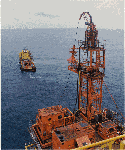
Successful workovers prove concept of boat-based CT operationsCrane and deck loading limitations impose constraints on the ability to perform coiled tubing (CT) workovers in the North Sea. Thus to minimize platform equipment requirements, increase economic value and allow a campaign style work program, Maersk Oil and Gas decided to test a new method of conducting CT interventions from a supply vessel to a platform. This concept was described in a recent technical paper.1 The technique involves placing the CT reel and other associated equipment on a supply vessel while installing the minimum required intervention control items on the platform. The long term goal is to position only the CT injector head, tower frame and control items on the platform while locating all other related equipment on the supply vessel. Applications. Maersk had two potential North Sea applications for the concept. In Dan Bravo field, wells were drilled from early-generation, four-legged wellhead platforms that confine available footprint size and equipment weight to about 18,000 lb. Most wells are horizontal multi-zone producers and injectors utilizing sliding side door completions. Currently, coiled tubing or other "stiffline" techniques are used to perform well interventions, which normally include production log surveys or the manipulation of sliding sleeves to improve reservoir management. The second application involves the unmanned "Star" platforms, which have no facilities nor capacity to lift or accommodate CT equipment. Until now a jack-up has been required to perform CT operations at these locations. Initial tests. Maersk and Schlumberger Dowell initiated a feasibility study of the vessel-based CT technique and structured a development plan. The first phase included planning related to the logistical and technical requirements of the project. To confirm theoretical values, calculations and procedure and equipment applications, a full-scale operational test was performed in a harbor before committing to an offshore operation. After the harbor trials were successfully completed, a complete HAZOP was performed to evaluate equipment procedures and overall safety. These trials were performed on a larger scale at an offshore manned installation. Major findings of the HAZOP covered three main areas:
The normal CT disconnect procedure that was established during planning included bleeding off pressure on the CT prior to breaking any connection or cutting the tubing. A time of 20 min was considered a realistic minimum for a planned disconnect, depending on the nature of fluids in the CT. An emergency disconnect procedure was established such that a disconnection would be completed within about 20 sec, and would only be performed in a crisis situation. And since there is not time to bleed off the CT before the cut, additional analysis was required. The HAZOP identified two types of hazards associated with cutting CT under pressure:
Since the emergency disconnect was a necessity, these hazards were investigated further so as to minimize or negate potential risks. An action plan was implemented in which a documented sequence of events was planned, and restrictive access to all areas that could be affected by an emergency disconnect was enforced.
Vessel type. The HAZOP team concluded that a dynamically positioned vessel should be used for the first operation. The vessel would need to be positioned precisely to minimize loads on the static structures and forces on the CT. To prevent overloading the platform tower structure, consistent position would have to be held in order to maintain the correct angle of elevation between the CT and fairlead entry points. A DP vessel would be able to work in poor weather, thus providing a wider window for CT work and lowering the likelihood of a potentially hazardous emergency disconnect. The DP vessel would avoid problems of deploying anchors around pipelines or platforms. And unlike an anchored vessel losing an anchor, it should not need to be re-oriented, which would overload the gooseneck and cause a failure in the gooseneck or jacking frame. Job execution. The operation began with the initial rig-up of equipment in the harbor and Danish Energy Agency (DEA) approval of the vessel before sailing for the North Sea. All major equipment was placed and welded to the deck of the vessel, ensuring that sufficient space was available for escape routes and for an area allowing personnel transfers by basket. The DEA required three alterations before a permit would be issued. A deluge system was specified for protecting the aft section of the vessel's accommodation from a potential fire; the deck was classified as a Zone II area for all operating equipment and procedures; and provisions were implemented to allow the captain the ability to implement the platform emergency disconnect function from the bridge. Placement, welding and construction of equipment on the vessel took 18 hr. Platform rig-up was conducted concurrently with vessel preparation. A standard CT package was assembled on the platform, the only difference being the orientation of the lower frame toward the sea and the use of a cantilever frame incorporating the platform fairlead and disconnect. Total time for platform rig-up was 48 hr. When the vessel arrived on location, wind was gusting at 31 knots and wave height was about 11.5 ft. Key personnel were transferred from the vessel to the platform and a safety meeting was held to clarify all lines of responsibility, communication and contingency and emergency procedures. The transfer of personnel and safety meeting took 4 hr. Once vessel-based personnel were transferred back, the vessel was positioned near the platform to hook up communication, data and transmission cables. Next, the wire cable positioned in the bottom of the tower frame was fed through the injector head, over the gooseneck and through the fairlead systems to the vessel. This cable system was used to facilitate the transfer of the CT from vessel to platform. As cables were fed out, the vessel established a position 300 ft from the platform. CT was pulled from the vessel, through the fairlead and into the injector head with an average load of 1,810 lb. A maximum load of 5,300 lb occurred as CT entered the platform fairlead. Once through the fairlead system, CT was pulled into the injector head chains and the skate system was activated to take over control of CT movement. Both of the cable systems used for conveying the transmission lines and CT contained weak points to ensure an automatic disconnect if tensile loads became too high. Conveying the transmission lines and CT from vessel to platform and related operational checks took 7 hr. The next stage involved making up toolstrings and conducting well interventions. Before the toolstring was connected, it was confirmed that both a 5/8-in. and 7/8-in. steel ball could be pumped from the reel inlet on the vessel to a ball catcher attached to the downhole end of the CT. This ensured that the catenary did not affect the ability to pump balls, and that either size of release tool could be activated while performing well intervention. The two well interventions consisted of a clean-up run to ensure a clear wellbore path, followed by a sliding side door manipulation. Operations within the wellbore did not deviate from standard intervention practices from the standpoint of tool operation or control. Throughout the intervention, gooseneck loads were monitored closely and combinations of vessel positions, distances, orientations and CT running speeds were attempted in order to view the resultant effect on the catenary and gooseneck loads. Gooseneck loads varied from 2,100 to 4,410 lb, with running speeds of 30 to 55 ft per min and vessel distances of 250 to 500 ft. Sea and weather conditions changed during the operation, allowing for a variety of circumstances to be tested. No incidents occurred during well intervention operations, and the initial areas thought to be of concern relating to gooseneck load and vessel-to-platform spooling operated smoothly and efficiently. All communication, data and transmission equipment also operated flawlessly, ensuring that changes in tubing direction and running speeds were manually synchronized from vessel to platform. Total operating time for making up toolstrings, pressure testing and conducting two well interventions to 10,700 ft was 26 hr. Once the final run was conducted, with the toolstring at surface and the swab valve closed, a trial emergency disconnect was initiated. The gripping rams on the platform disconnect were engaged before the shear / seal blades were activated. The cutting procedure on the platform was activated from the bridge on the vessel using the data transmission lines. The CT was then dropped freely into the sea without interfering with any part of the platform structure. It was then spooled onto the vessel-based reel without damage. Implementation of the planned disconnect took 2 hr. The vessel was then released and sailed for harbor. The total operating time to conduct a vessel-based CT operation from rig-up to release of the vessel was 87 hr. Evaluation of operations. The vessel-based CT operations were successful under the varying conditions expected in a North Sea environment. The 87-hr operation included 39 hr of actual CT work and 48 hr of rig-up time on the platform and vessel. Both well interventions proceeded without problem, and no anomalies were caused by the CT reel and related controls being located on the vessel. However, it is worth noting that running and pulling speeds for each intervention were kept slightly lower than normal. While connecting the CT and transmission lines to the pulling lines, it was necessary to situate the vessel very near the platform, which makes weather and sea conditions much more critical. When the vessel takes its station about 300 ft away from the platform, weather becomes less critical and proper monitoring of the CT catenary ensures a natural form of heave and roll compensation. Contrary to the HAZOP findings, which identified vessel position as an important factor in gooseneck loading, actual experience was that position had minimal effect on this load as long as the catenary was maintained. When the CT is connected, the vessel is free to move within a window of 150°, provided the aft end of the vessel always points toward the platform fairlead receptacle. Distance between vessel and platform also did not prove critical, and 200 to 400 ft proved optimal. Literature Cited
Due diligence surveys and rig inspectionsDavid Robin, DIS/CON International, Inc., Lafayette, Louisiana Seeing a Minerals Management Service (MMS) helicopter land on your rig is like seeing blue lights in your rearview mirror. However, like the policemen who are protecting us, MMS rules and regulations are designed to protect the safety of personnel and our environment. In order to be proactive, Chevron USA elected to have outside mock MMS inspections from a third party company. The operator also implemented a daily structured routine inspection designed to eliminate the possibility of routine occurrences of violations of MMS rules and regulations. Outside mock MMS inspections are performed every six weeks or at the start-up of a new well, whichever comes first. A due diligence survey is an inspection or audit of a field or lease that is for sale. It is conducted to determine if there are any hidden liabilities or potential problem areas which may exist and that are not readily evident to the purchaser. The survey should be conducted by individuals or teams who are knowledgeable about day-to-day field operations, and all of the equipment necessary for those operations. Equally important is a complete knowledge of regulatory rules, regulations and operating procedures imposed by governmental agencies. Procedure. An inspection tour of the facility is conducted, noting the general structure information. A few of the items inspected are: structure condition; lifesaving equipment; pipeline working pressures and operating pressure range histories; production equipment and its condition; compressors and their capacities; types of product metering; and engines and their maintenance histories. Potential problem areas concerning the above are realized by intense scrutiny of past records — this is by far, the most important area of concern. Without the availability of these records, a quality due diligence survey cannot be accomplished. For example, a due diligence survey was conducted at the request of Stone Energy on a prospect under consideration. The following areas of concern were noted in the review of the structures involved. Area 1. While making a visual inspection of the structure and associated production equipment, it was noted that extensive patchwork had been performed on the underside of the water clarification unit (precipitator). A review of the structure and maintenance records revealed a report by an X-ray company which had been contracted to do an evaluation of the production process vessels. The report indicated, in part, that due to the patchwork that was performed and lack of documentation on the repair being performed by a code welder, the precipitator could no longer be considered a coded vessel under the ASME boiler and pressure vessel code. The discovery of these records indicated that a replacement of this vessel would be required. Aside from replacement cost, the production downtime associated with the replacement could be substantial. Area 2. A bent and broken structural member near the boat landing was noted in the course of the inspection. A replacement of this structure member would require mobilization of a construction and welding crew; and a substantial outlay of resources would be required. Area 3. Excessive corrosion on structural support beams on the upper portion of the structure was noted. Damage to the supports indicated an in-depth evaluation of the weight load requirements. These requirements are a factor in determining the size of a workover rig that could be supported by the structure. Area 4. As per CFR 250.142, a Level 3 inspection is required of the underwater structural members every six to ten years. During the review of required MMS documentation, it was discovered that the Level 3 inspection was due. Because of the magnitude and cost of this type of inspection, a bid price could have been renegotiated, resulting in a significant cost savings. The above review indicates that a properly executed due diligence survey is a valuable tool designed to expose hidden flaws and give the prospective purchaser an in-depth knowledge of the properties being offered for sale. Inspection need examples. Due to the increased activity in the Gulf of Mexico, some drilling contractors are experiencing a shortage of trained personnel. Consequently, unfortunate accidents have occurred, which could have possibly been avoided with properly trained personnel. In one example, after having accomplished required testing / calibration of the atmospheric gas detectors on a Chevron USA rig, an MMS inspection took place. Armed with the knowledge that the gas detection equipment had been tested the previous week, the company representative felt confident of positive inspection results. However, during the inspection, the gas detectors in the mud pit room were found to be inoperable. After investigating this incident, it was found that newly hired roustabouts had unknowingly directed a high-pressure water stream onto the gas detector sensor head, rendering it inoperable. This helped the Chevron personnel involved realize that an outside mock MMS inspection would be a valuable tool in their efforts to stay in compliance with MMS rules and regulations. In another case involving a different operator, during a mock MMS inspection of a snubbing operation, it was discovered that a diesel-engine-driven pump was being used as one of the accumulator pumps. During the inspection of the automatic air intake shutdown on this engine, the engine shutdown caused a fireball to be projected from the exhaust piping. Under close scrutiny, it was discovered that this engine was not equipped with a required spark arresting muffler. An extreme hazard existed in that the unit was located within ten feet of a producing well. Aside from the obvious benefit of staying in compliance with regulatory rules and regulations, other benefits derived from mock MMS inspections include: 1) the additional emphasis placed on safety; 2) freeing the contractor and company representative to devote more time and energy to the actual drilling process; and 3) the peace of mind derived from knowing that you have gone that extra mile to assure a safe, accident- and incident-free work environment. With today's rig day rates at all-time highs, every effort should be taken to assure that the drilling process goes uninterrupted. In conclusion, mock MMS rig inspections, performed by outside independent inspectors that
are not influenced by company policy, have proven to be beneficial tools in the
identification of occasionally overlooked problem areas. However, a daily structured
checklist of commonly neglected items that could cause accidents or the issuance of an MMS
incident of non-compliance should be instituted. This task should be given to a team of key
personnel on the rig. A checklist would create an awareness of imposed government rules and
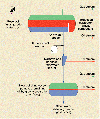
regulations on a daily basis. The author Terra Nova development, new FPSO turret mooringIn mid-February, the Terra Nova owner companies announced their decision to proceed with development of the field, located 225 mi ESE of St. John's Newfoundland, in the Grand Banks area, in 300- to 330-ft water. Hibernia field lies about 25 mi to the NW. PetroCanada is the operator, on behalf of itself and six other owners: Mobil, Husky, Norsk Hydro, Chevron, Murphy and Mosbacher. Terra Nova has three principal structural blocks: the Graben, the East Flank and the Far East. As reported in Atlantic Petroleum, March 1998, the Graben and the East Flank will be developed first, utilizing up to 24 subsea wells, including 14 producers, 7 water injectors and 3 gas injection wells. The Far East block could see 12 wells, including six injectors. Development overview. The subsea wells will be drilled from a semisubmersible rig and be completed in glory holes to prevent iceberg scouring. They will flow to the vessel location through buried flowlines and onto the FPSO through flexible flowlines connected to the riser base. Water and gas injection, and subsea well control will be directed from the FPSO via umbilicals. The field is estimated to contain more than one billion barrels OIP, with more than 370 million bbl recoverable. The 950-ft long FPSO can handle 125,000 bopd, plus 180,000 bpd water injection (which is expandable), plus 125 MMcfd gas. Peak production of 125,000 bpd is expected, to be stored in 14 cargo tanks with 960,000-bbl capacity and exported to shuttle tankers. In an early schedule published by the operator, vessel construction is underway with float-out in early 2000. Topsides construction started early this year. Drilling is to start in summer 1999, using the Transocean Explorer semi, with six wells to be completed by late 2000. Drilling will be preceded by glory hole and template construction. Terra Nova Alliance. The massive construction effort will be made possible by a major contractual structure involving: Petro Canada (PC); Coflexip Stena Offshore (CSO); ShawMont Brown & Root (SBR); Halliburton Energy Services (HES); PCL Constructors (PCL); FMC, including SOFEC and Kongsberg (FMC); and Doris ConPro (DC). The principal contribution of these Alliance members is depicted in Fig. 1 Turret mooring system. SOFEC, a subsidiary of FMC Corp., is providing a heavy duty disconnectable turret mooring system to deal with a unique combination of environmental conditions. Terra Nova is exposed to the seasonal presence of sea ice and icebergs; and ability to quickly disconnect the vessel from the fixed mooring and safely move off location is key to the field development concept. The turret design incorporates a 56-ft-dia., 1,300-mt, disconnectable "spider buoy" which supports nine chain mooring legs and 19 flexible risers and umbilicals (14 to be installed in the initial phase). The FPSO can be disconnected from the spider buoy in four hours, for a planned disconnect (including flushing and blow-down of the production and injection lines). In an emergency, the disconnect can be done in 15 minutes. Unlike other disconnectable systems, the FPSO will remain connected in a 100-yr storm condition. Production and injection lines are connected to the turret via the spider buoy, and quick-connect-quick-disconnect couplings, and are routed to the fluid swivels through a versatile manifold system. The swivel stack comprises three high-pressure water and gas injection swivels, six medium-pressure toroidal swivels, two multipass utility swivels, an electric power swivel, fiber optics swivel and electric control swivel. The turret, including the spider buoy, swivels, equipment, piping and structure is about
230 ft tall and weighs more than 4,000 mt. This massive facility, depicted in
Fig. 2, and will be the largest
disconnectable turret mooring system constructed to date.
New chemical improves produced water treatmentChevron and Baker Petrolite have teamed up to develop and successfully apply a new chemical that removes small insoluble oil particles from separated water. For difficult-to-treat production fluids on Chevron UK Ltd.'s Alba platform in the UK North Sea, the operator was able to clarify discharge water to below industry-standard levels using the chemical, in combination with addition of a new polishing vessel to the treating system. Treating requirements, problems. As Durham notes in his 1993 SPE presentation,1 "Governmental regulations applying to produced water discharge in the Gulf of Mexico and the North Sea have become increasingly stringent and have made it difficult for many platforms to remain in compliance with respect to oil content in the overboard produced water. "Most platforms are equipped with water treating systems that could treat the current volume of produced water at pre-1987 specs of 72 ppm. In many cases, however, these same systems are not able to reduce the oil content to post-1987 EPA specs of 48 ppm with the use of conventional water clarifiers. Continued increases in water production are also further taxing these systems. "Because of the changes in EPA specs, many producers in the Gulf of Mexico and the North Sea were facing the possibility of being out of compliance unless new water treating equipment could be installed, which for many platforms would have been very expensive due to space restrictions." In Chevron's case, Alba was the first large-scale oilfield in the North Sea to produce very "heavy" oil, which presents particular processing problems when separating water from produced oil.2 The thick, viscous oil has a specific gravity of 20.6°API compared to a typical North Sea crude of 30°API, and a tendency to form difficult-to-handle emulsions in the main separators. The unconsolidated nature of the Alba reservoir — in which the crude is loosely combined with sand in a highly porous and permeable formation — results in quantities of sand being co-produced with the oil and water. Handling this material presents a further technical challenge. As water production levels have increased since Alba came onstream, the field has produced water with oil content greater than the 40-ppm industry standard. Although scientific studies have shown that Chevron's water discharges posed little threat to the environment, due to natural dispersion and dilution, the company, with the cooperation of the Department of Trade and Industry, has been working on bringing the levels down to below this level. Improved treatment program. In mid-1997, Chevron initiated the Alba program by installing a 20-mt polishing vessel, which uses gravitational forces to clean water separated from the main processing vessels. A new chemical was developed for use in the polishing vessel to help Alba's especially small oil droplets join together and float away from the water in its final clean-up stage. The chemical, W285, is supplied by Baker Petrolite. It was developed with the help of Chevron Petroleum Technology Co. for the Gulf of Mexico. The promised results were realized late last year and additional supplies were shipped to Aberdeen from the U.S. during November and December. Baker is presently manufacturing the chemical in the UK. The operator says conventional hydrocyclone technology was not effective on its own due to the small oil droplet sizes. The original platform design had assumed that larger droplets would be cleaned up at a higher efficiency. What was needed was the combination of a new vessel downstream of the hydrocyclones, together with the new chemical, to clean the water to an acceptable level. With the new chemical, in combination with the new vessel, oil-in-water levels of 35 ppm have been consistently recorded, and the operator believes these can be reduced to below 30 ppm in the longer term.
How it works. The new chemical is a proprietary development of a dithiocarbamate (DTC) water clarifier. The background of the chemical system is presented by Durham, 1993.1 In an internal memo, Baker notes, "Lab and field test data indicate that DTC water clarifiers function by reacting quickly with metals in the produced water to form a floc that removes oil from produced water. The speed of the reaction of the DTC with metal ions to initiate floc formations allows the DTC water clarifier to treat water much faster than conventional systems." In the February 1998 feature in Chevron Today,2 the operator further describes the process, as follows. New dithiocarbamate (DTC)-based water clarifiers were developed to remove insoluble hydrocarbon in offshore water treating systems in which other conventional and first-generation DTC clarifiers were found to be ineffective, create unmanageable side effects, or are less cost effective. The action of the DTC chemicals removes oil and solids from produced water to form a water insoluble paste which takes the form of small particulate flocs. Under correct mixing and application conditions, the chemistry works very fast and flocs are formed typically within one minute from the point of application. As these flocs are very light, they rapidly float to the water surface enabling them to be skimmed off in the produced water degasser vessel. The action of the DTC chemical produces larger oil particles to enhance the efficiency of oil removal in produced water hydrocyclones. The reject oil from the hydrocyclones and skimmed oil from the produced water degasser vessel are recycled into mixed production on a continuous basis, allowing the floc to dissolve or disperse in the oil phase. The operator further notes that, as a field matures and oil reserves deplete, there is a rise in the volumes of water which are produced. And despite the efficiency of the separation processes, produced water will always contain small amounts of residual oil. Chevron has, for several years, supported research into the treatment of water offshore, through the Marine Technology Directorate's program, which is addressing scientific and engineering problems associated with water processing for reservoir injection and treatment of produced water prior to disposal. It is continuing to fund research in this area through participation in the Produced Water Management program run by the new Centre for Marine and Petroleum Technology. And it also funds various other research projects in this area through its U.S. technology company. Acknowledgment
Literature Cited
Accelerated development of Brazil's huge Roncador fieldBased on recent reports in Brasil Energy,1 and three presentations by Petrobras at OTC 1998,2,3,4 the following article overviews present and future programs for the 2.9-billion-bbl development in Brazil's deepwater Campos basin. Located in the northern part of this offshore basin, some 85 miles from the coast, in 4,900 to 6,200-ft water depths, Roncador is Petrobras' newest giant discovery. With only two wells drilled and tested so far, the RJS-436 discovery in October 1996 and the RJS-513 in January 1998, the operator is still making basic reservoir and geology evaluations.2 Yet plans are underway to accelerate first oil and get permanent production facilities installed. Field-wide reserves are now estimated at 2.9 billion bbl,3 and reinforce the country's hydrocarbon resources, of which an estimated 68% lie offshore in deep / ultra-deep water.4 Development will basically proceed in three phases, called Modules. Module I should come onstream in April 1999, only 2-1/2 years after discovery, and peak in mid-2001 at 190,000 bopd. Plans for Modules II and III for northern and southeastern areas, respectively, are highly flexible, depending on forthcoming well / reservoir / productivity data. Conceivably, they could add 180,000 bopd by mid-2003 and bring total production up to 400,000 bopd, plus 250 MMcfd gas by 2004. Presently, four additional exploratory wells are being drilled, the 3-RO-1-RJS, 3-RO-2-RJS, 3-RO-3-RJS and 3-RO-4-RJS, to utilize Peregrine 1, Sedco 707, Noble Leo Segerius and N. R. Eason semis. And as reported,1 Petrobras is ready to charter Reading & Bates' Seillean FPSO for early production from the RJS-436 discovery, and probably one of the four new wells. Presumably, the vessel will operate in DP mode in the 6,100-ft water over RJS-436; well rates are in the 10,000-bopd range. Petrobras is eager to develop Roncador because it is a major development, as well as an exciting deepwater technical challenge that it has been preparing for under its PROCAP (Petrobras Technological Development Program on Deep Water Production Systems) and PROCAP-2000 initiatives.5 The operator also wants to "stake its claim" for Roncador to avoid having it put up for possible privatization under Brazil's new oil law that targets areas not yet onstream.1
Module I. As outlined in the April Brasil Energy feature, Module I will produce through a system that includes 26 wells: 19 producers and seven injectors. The wells are located in water depths of 5,200 to 6,100 ft, and the host unit will be Petrobras 36, the former Spirit of Columbus and Sana semi, presently being converted in Quebec, Canada, for FPS work. It will operate together with the FSO unit, P-47 (Eastern Strength), undergoing conversion in Cadiz, Spain. By the end of 1999, there will be 11 wells onstream, producing about 100,000 bopd. Final connection of the wells to P-36 should occur by May 2001, when production from this module will hit its peak of 190,000 bopd. Subsea wells will flow to the P-36 site via individual flowlines to a gas lift and control subsea manifold under the vessel, and then to the vessel through individual risers; the manifold also provides for flowline pigging.4 Treated crude will be exported from P-36 through three 10-in. pipelines to the FSO vessel, moored in shallower water outside the field. Offloading from that point to tankers will be initiated, until final development dictates field potential and the design of a pipeline, likely in Module II. A gas pipeline to shore is also under study, to define the correct diameter.4 Brasil Energy notes that gas will be brought out through the Namorado platform via a 20-in.-dia., 60-mi long pipeline. Modules II and III. Petrobras has plans for two more development stages in Roncador, the scope of which is being re-evaluated during the course of this year as results from exploration wells become available.1 According to preliminary data, Petrobras is studying the possibility of installing a second module by 2001. Module II could have 28 wells (20 producing and eight injecting), connected to a platform with capacity for 180,000 bopd. For Module III, tentative plans call for 21 wells (15 producing and six injecting), connected to a 100,000-bopd platform, by July 2003. With these and other modules, Roncador production could rise to 400,000 bopd and 250 MMcfd gas sometime between 2003 and 2004. Development costs for Modules II and III are estimated at $2.9 billion and total overall investment estimated through 2005 is in the range of $4.5 billion.1 Literature Cited
Joint industry FPSO research progressAs featured by the Maritime Research Institute Netherlands (MARIN) in its special OTC '98 issue of Marin Report, April 1998, the FPSO Integrity Joint Industry Project is now onstream. The aim of the JIP is to produce a validated FPSO lifetime prediction model and a comparison of existing calculation procedures with real-world data. The 20 companies supporting this work have initiated an open forum for joint research work on FPSOs. The following presentation, based on the above noted feature, describes the FPSO Integrity JIP, an ongoing research project for structural monitoring of a working vessel, and the "next step" into a Joint FPSO Research Forum. Further details by an active member of Conoco's team, and contact information are provided. Joint FPSO research evolution. The present "Integrity" JIP is supported by a large number of leading companies in the field of FPSO research, engineering, approval and operation. This illustrates the current industry demand for FPSO (Floating production storage and offloading) development as well as recognition of the need for cooperation throughout the industry. These companies are participating in the FPSO Integrity JIP: American Bureau of Shipping, Amerada Hess, Astano, Bluewater, Bureau Veritas, Chevron, Conoco, Det Norske Veritas, Exxon, Germanischer Lloyd, Health & Safety Executive, Hyundai Heavy Industries, Lloyd's Register, MARIN, Mitsubishi Heavy Industries, Nevesbu, Petrobras, Shell, Statoil and Texaco. To achieve better market demand, initiation and support of future JIPs in this field, it was proposed to use the existing FPSO Integrity Group as a stepping-stone to the establishment of a Joint FPSO Research Forum. This idea was circulated and received strong support. On January 28, the FPSO Integrity Working Group decided to pursue this initiative and invite other companies to join the proposed open forum. A special function was organized for this purpose on May 8, in Houston, during the Offshore Technology Conference. During this meeting, progress reports were given on several ongoing FPSO JIPs such as FPSO Integrity (MARIN), Shipfat (DNV) and LNG FPSO (Chevron). New proposals for JIPs were identified and discussed. This meeting was the actual launch of the Joint FPSO Research Forum. Further information on this industry effort is presented in the accompanying presentation, see box. Structural monitoring project, system. In August 1997, first oil was produced by the Glas Dowr, an FPSO located in the Durward and Dauntless field in the North Sea. The vessel, operated by Bluewater for Amerada Hess, is equipped with an extensive structural monitoring system. The 3-year monitoring campaign is part of the Integrity JIP. It is designed to provide a firm basis for development of consistent standards and analytical procedures for fatigue, and lifetime predictions regarding tanker-based floating production systems. As part of the JIP, five classification societies are conducting in-house hydrodynamic and structural analysis of the vessel for purposes of both mutual and real-world data comparison. A new fatigue load assessment and lifetime calculation method is to be developed and implemented in software to be delivered to the participants. Regarding the monitoring system itself, during its conversion from a new double-hull tanker into an FPSO, Glas Dowr was equipped by MARIN's Trials and Monitoring Department with a dedicated monitoring system. This comprises continuous measurement of global and local hull stresses, tank / wave pressures and relative wave heights at several cross-sections. In addition, the turret has been equipped with special strain gauges to measure mooring system loads. Both wave frequency motions and low frequency excursions are being recorded. The campaign
also includes monitoring of operational conditions (heading, draughts, tank levels), and
detailed in-field wind, wave and current climates. The monitoring system was commissioned in
October 1997. Data is being processed at MARIN and used for various purposes, including
comparisons by the classification societies.
Copyright © 1999 World
Oil |
|||||||||||||||||||||