ALEXANDER RUDNIK, BURT BONIN and BRENDON WEBB, Coil Tubing Services, a Schlumberger Company; LUKE LEFORT, Schlumberger
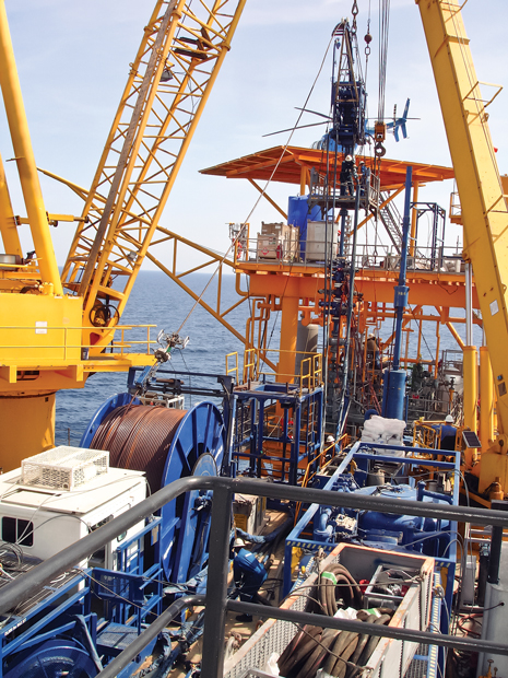 |
| After several unsuccessful attempts with wireline to dump-bail cement, the operator successfully used CT to plug the bottom zone of a deep, high-pressure well with cement. |
|
As a result of production having drained once-prolific reservoirs, Gulf of Mexico (GOM) operators are dealing with an increase in well abandonments. This activity is also spurred by environmental concerns and governmental regulatory agencies. Many such well plugging and abandonment (P&A) activities are now performed using CT, which eliminates the need for a drilling rig.
Cement placement is an essential part of every P&A operation. Deep wells (exceeding 20,000-ft, MD) with BHST greater than 400°F and an aggressive H2S/CO2 environment, add challenges to the cement slurry design. Furthermore, operations need to be executed safely and within the limits of CT equipment.
An operator needed to P&A a well in the GOM Mobile Bay block. No previous high-pressure, high-temperature (HPHT) cementing operations through CT at BHSTs greater than 400°F had been performed in the GOM. One of the key challenges for this CT intervention was designing a cement system for 425°F, BHST, to be pumped through a 23,620-ft, 1½-in. OD CT string. Concentrations of 75 ppm H2S and 4% CO2 increased the complexity of the operation. After several unsuccessful attempts with wireline to dump-bail cement, the operator successfully used CT to plug the bottom zone of this deep, high-pressure well with cement.
BACKGROUND
A single completion well, drilled in 1999, was shut-in after producing sand. As a result, the operator decided to abandon the well. The well contained H2S, with a concentration of 75 ppm and 4% CO2. Multiple attempts to inject into the well were unsuccessful. The operator then attempted to dump bail cement with a 30-ft dump bailer tool (2-in. OD), but the cement set prematurely in the bailer, due to the high bottomhole temperature, and the dump bailer was left in the well. The top of this 57-ft fish was at a depth of 22,607 ft. The operator was unsure of the fluid inside the wellbore, and 12 lbm/gal oil-based drilling mud was in the casing. The CT job objectives were:
- Clean out the well to the top of the fish at 22,607 ft
- Pump 8 bbl of cement with a full-bore nozzle to lay a 514-ft cement plug in the 5-in. casing from 22,093 ft to 22,607 ft
- Perforate the 3½-in. tubing at 19,500 ft with tubing conveyed perforating (TCP) guns
- Pump a 300-ft intermediate cement plug in 3½-in. tubing from 19,200 ft to 19,500 ft with a full-bore nozzle
- Perforate the 3½-in. tubing at 14,700 ft with the TCP guns
- Pump a 300-ft top cement plug in 3½-in. tubing from 14,400 ft to 14,700 ft with a full-bore nozzle
KEY CHALLENGES
Several key challenges were encountered during this operation. The well had a maximum potential wellhead pressure (MPWHP) of 13,260 psi, which, in combination with well depth and the H2S/CO2 presence, demanded a high level of job engineering, testing, preparation and contingency planning. Ensuring that the pipe and material limitations were respected at all times during the well intervention was essential to the overall job success.
High BHST. One of the key challenges specific to the cementing portion of this CT intervention was the high BHST. A cement system had to be designed for 425°F, BHST, and be pumped through a 23,620-ft CT, 1½-in. OD string. The main properties of the cement slurry that were to be closely monitored included stability, rheology, fluid loss and thickening time. Friction pressure and slurry stability are major concerns when pumping cement slurries through CT.
The cement slurry was a Bingham Plastic fluid, whose viscosity is a function of its plastic viscosity and yield point. These properties describe the amount of solids and their distribution in the system. Therefore, it is essential to add only the required amount of dispersants to avoid over-dispersing the slurry, which might result in loss of stability, settling of solids and free water, and subsequently, plugging of the CT. For the cement slurry thickening time, conventional API test schedules use bottomhole circulating temperature. However, for slurry to be pumped through CT, a rapid temperature increase was expected, mainly due to the small flow areas and rates.
Tests were carried out using the BHST and the recommended modified API schedule to reflect actual conditions encountered during cement placement. The BHST was also higher than the temperature rating of the conventional O-ring material in the BHA. The Viton O-ring seals used in the CT connector are rated at 350°F in seawater. When seals are exposed to temperatures above the temperature rating, there is a limited period of exposure time before the seals fail. Fluoroelastomers, such as Viton, have an exposure limit of 50 hr at 425°F. The risk of O-ring failure was controlled by not operating the BHA in the well for a time period that exceeds the 50-hr exposure limit for the Viton seals.
H2S and CO2. Another operating challenge was the potential for the presence of 75 ppm H2S, and 4% CO2, in the well. Precautions were taken to minimize the exposure risk to personnel on location, and prevent corrosion and sulfur stress cracking damage to the CT string. Chemical injection pumps were tied into the stack and used to coat the CT with a high-temperature H2S and CO2 corrosion inhibitor, as it was run in the hole to protect the CT pipe. Slugs of this inhibitor were also pumped down the CT periodically to recoat the pipe.
In addition, H2S monitors were worn by personnel on the deck at all times, and self-contained breathing apparatus were placed in various locations on the deck of the lift boat and platform. Weekly H2S safety drills were held to maintain personnel awareness of response plans. Furthermore, the well was kept in an overbalanced condition to prevent the influx of wellbore fluid. A scrubber and flare system were available for use in the event that returns contained H2S; however, no H2S was detected at surface during the operation.
Casing fluid disposal. A third challenge was the limited platform deck space available for disposing the 12 lbm/gal oil-based drilling mud that needed to be circulated out of the casing during the operation. A fluid swap was planned before pumping the balanced cement plugs. However, after the first set of perforations was made at 19,500 ft, circulation was established, with 32 bbl of seawater being pumped down the tubing, and returns coming up the casing. Casing return was seawater, so the operator decided to abort the fluid swap operation. Cement was mixed and pumped, with plans to recirculate the casing return fluid. Shortly after beginning the displacement, drilling mud from the casing was observed at surface. Once it was mixed with the seawater, an emulsion quickly developed and clogged the suction lines going to the fluid pump, causing the pump to cavitate. The digital counter was rendered inaccurate, so the barrels were visually counted, and seawater was used to complete the displacement. A total of 100 bbl of casing fluid was emptied into marine portable tanks for disposal.
CEMENT DESIGN
The key challenge in the cement design was achieving slurry stability. All of the additives in the cement system were used outside of their documented application range. Laboratory testing was performed, according to the recommended, modified API schedule. The slurry was conditioned at BHT for 30 min and then cooled to 190°F (the maximum temperature rating for the laboratory equipment) for rheology measurements. It took 3 hr for the slurry temperature to drop from 425°F to 190°F. High concentrations of retarder were necessary to ensure an adequate thickening time. Determining the optimal additive amounts, to achieve the required fluid loss, proved to be more challenging. In addition to the fluid-loss additive, the antisettling agent and high-temperature gas migration control additive affected the fluid loss. Several laboratory tests were performed to optimize the cement system that would be batch-mixed using Class H cement:
- 5%, by weight of cement, silica
- 0.05 gal/sack, antisettling agent
- 0.05 gal/sack, antifoaming agent
- 0.06 gal/sack, high-temperature gas migration control stabilizer
- 0.50 gal/sack, high-temperature gas migration control additive
- 0.20 gal/sack, fluid loss additive
- 0.20 gal/sack, high-temperature retarder
- 1.40 gal/sack, retarder for set control
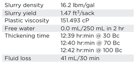
Table 1 summarizes the cement slurry properties. The thickening time of the cement slurry at 70 Bearden Units of Consistency (limit when the slurry is considered as not being capable of being pumped through the CT) was determined to be 12 hr and 40 min.
| Table 1. Key cement slurry properties. |
|
The pumping schedule for the first cement plug to be pumped down the CT is shown in Table 2. The gelled spacer fluid was prepared by mixing 10 bbl of fresh water with 2 gal of antifoaming agent for circulation in the batch mixer, during which time, 20 lb of an antisettling agent were added to the batch mixer. After allowing 45 min for the antisettling agent to hydrate, the spacer fluid was ready to be pumped downhole and transferred to the displacement tanks.
| Table 2. Pumping schedule for cement plug from 22,607 to 22,093 ft. |
 |
CT STRING DESIGN/VERIFICATION
The CT string design was a key element in allowing the service company to intervene in a well with 13,260-psi MPWHP. The string details for the 1½-in. OD, HS-110 CT string used for this operation are shown in Table 3.
| Table 3. CT string specifications. |
 |
The maximum allowable collapse pressure for each CT wall thickness change depends upon the forces applied to the CT while it is in the well. The maximum well control pressure (MWCP) is the maximum pressure for well control, only. MWCP should not exceed any of the following thresholds:
- Category pressure limit +1,500 psi
- 1.5 times the MPWHP, or the working pressure of the component with the lowest pressure rating
- The CoilLIMIT coiled tubing pressure/tension limit model curve value
The working pressure of the component with the lowest pressure rating in the well control stack, including the wellhead or connections and reel components.
Therefore, the MWCP is determined by the CoilLIMIT 80% collapse limit for each wall thickness as per Table 4. The MWCP values are based on the assumption that the well is dry (filled with 1.64 lbm/gal, gas). The actual MWCP during the operation was dictated by the CoilLIMIT working envelope. The CoilLIMIT design plot with the CT positioned at 22,600 ft is shown in Fig. 1.
| Table 4. MWCP values for all CT string sections. |
 |
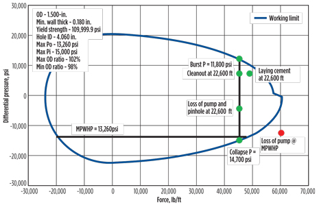 |
| Fig. 1. CoilLIMIT design plot with CT located at 22,600 ft. |
|
In the event that a well kick is detected with the well full of 8.6 lbm/gal seawater, the CT would be halted, and the well would be choked in an attempt to stabilize the returns and achieve bbl-in/bbl-out. With the well full of 8.6 lbm/gal seawater, the maximum wellhead pressure to balance the well was 5,200 psi. The pump rate would be increased, and the wellhead pressure (WHP) maintained at 5,200 psi to keep the well overbalanced until the kick is circulated out. An annular volume of seawater would be pumped, and if the pressure stabilized, a review would be performed to determine if the operation should be continued. If the pressure did not stabilize, the CT would be pulled out of hole to the surface. However, if well control was lost, the contingency plan called for pulling the CT out of hole to 6,000 ft, the minimum safe depth at which the CT would be able to withstand the MWCP in the worst case scenario (CT string failure and loss of fluid pump). If the WHP increased over the MWCP defined for each CT section, the CT would be cut at surface with the blowout preventer shear rams, and the well would be shut in.
DEFORMATION ANALYSIS
Each time the CT is run in and out of a well with high-circulating pressure, there is a possibility that the tubing diameter will increase to prevent the tubing from passing through the stripper, rendering the tubing unusable for future use. This effect, called pipe ballooning, can be prevented if the proper CT material and tubing size are selected for the anticipated loading conditions, such as circulating pressure and the number of tubing passes over the reel and gooseneck required to complete the job. In addition, high-pressure cycles of the CT string over the reel core and gooseneck will inevitably lead to wall thinning, which decreases the effective working envelope for that section of the CT string. The CoilDEFORMATION coiled tubing elongation and ballooning deformation model was used to verify that the correct CT material and size (OD and wall thickness) were chosen for this operation.
| Table 5. Coil deformation analysis results, based on CT string history and predicted operating load number of cycles. |
 |
As shown in Table 5, it is reasonable to conclude that a 5% wall-thickness reduction (based on minimum CT wall thickness) must be used in the design for this particular well intervention. The results also show that the CT string exhibits satisfactory, permanent deformation changes that will not create significant problems, including compatibility of the CT string and pressure control equipment. Ballooning of the CT OD to 1.513 in. is within an acceptable tolerance for the CT pressure bushings, both standard (0.03 in.) and oversized (0.08 in.) bushings clearance.
RISK MANAGEMENT
Several preventative and mitigative measures were taken to manage the risks associated with this operation and ensure that it was completed safely. All required laboratory testing of the cement slurry was performed. A thorough job procedure was completed for this operation that included detailed cement mixing procedures. A quality assurance/quality control kit for cementing operations was used on location to test the cement after it was mixed and before it was pumped downhole. A digital scale was also used to ensure accurate chemical weights, when mixing the cement slurry. High-temperature corrosion inhibitor was pumped, and applied to both the inside and outside of the CT pipe during the operation.
The mixing area was designated as a hazardous area, and non-essential personnel were kept clear of this area to minimize exposure to the personnel. A backup fluid pump was rigged up on location in the event that the primary pump failed at any time during the operation. All crew members wore proper personal protective equipment, including H2S monitors. The H2S detectors were set up on the return tank, and a scrubber and flare system was also used. In addition, rescue equipment was set up on the platform and the lift boat, in the event of an emergency.
JOB EXECUTION
Table 6 summarizes the CT runs made into the well.
| Table 6. CT run summary |
 |
First run: Fill cleanout and pumping a cement plug. The well’s initial shut-in tubing pressure (SITP) was 2,750 psi. While the CT was being run in the hole, the surface-controlled subsurface safety valve (SCSSV) was tagged and had bled down to 0 psi. The control line was repressurized to 7,500 psi and monitored. Once the gauge held steady, the CT was run in the hole again and did not tag the SCSSV. After opening the SCSSV, the WHP increased to 6,750 psi, where it was maintained (Fig. 2) as the CT continued to be run in the hole, while pumping 0.25 bbl/min seawater. The CT tagged fill at 20,123 ft and cleaned out to 22,610 ft. After circulating a bottoms-up, an injection test was performed, but the WHP increased to 7,500 psi and injection was not established. Eight bbl of cement were pumped in the 5-in. casing from 22,607 ft to 22,093 ft. Then, the CT was pulled out of the well, maintaining a WHP of 6,800 psi after spotting the cement. After waiting 26 hr for the cement to set, a negative test was performed on the cement plug, with pressure on the well increasing back to 6,800 psi after 3 hr.
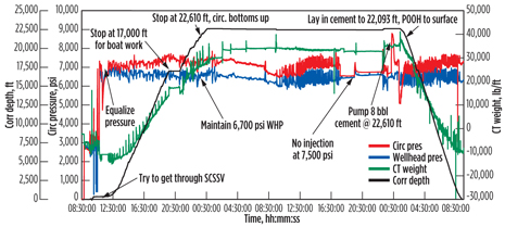 |
| Fig. 2. CT post-job data acquisition plot for Run #1. |
|
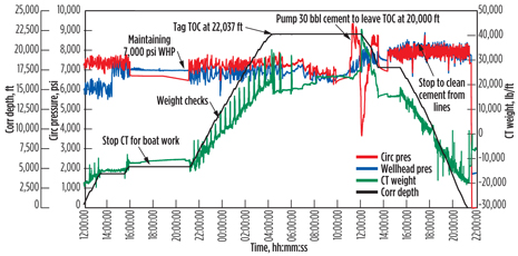
Second run: Pumping the cement plug. Because a successful pressure test was not achieved on the first cement plug, the decision was made to pump another cement plug into the well. The CT was run in hole and tagged the top of cement (TOC) at 22,037 ft, Fig. 3. On this run, 30 bbl of cement were pumped in the 5-in. casing and 3½-in. tubing, from 22,037 ft to 19,900 ft. The CT was then pulled out of the well, maintaining 7,500 psi, WHP, after spotting the cement. After waiting 18 hr for the cement to set, a negative test was successfully performed. The tubing and casing were then pressure tested to 1,000 psi for 30 min.
 |
| Fig. 3. CT post-job data acquisition plot for Run #2. |
|
Third run: Perforating with tubing conveyed perforating (TCP) guns. The CT was run in the hole and tagged the TOC at 19,874 ft, where the CT was picked up to 19,500 ft and a 7/16-in. ball was pumped down the CT. After pumping three reel volumes of seawater, there was no indication that the ball had seated. The CT was then pulled out of the hole to 10,000 ft, and acquisition data were reviewed. It was determined that the TCP guns likely had not fired. Due to the communication between the CT and the CT tubing annulus, there was a possibility that the tools were lost in the hole. As a result, the slim tool and live TCP guns undeployment contingency procedures were followed, to prevent pulling out of the packoff or detonating the guns while retrieving them from the well. When the CT reached surface, the TCP guns were safely retrieved without incident. The BHA was inspected, and the O-rings on the CT connector were found to be melted, which prevented the pressure differential across the firing head that was needed to fire the TCP guns.
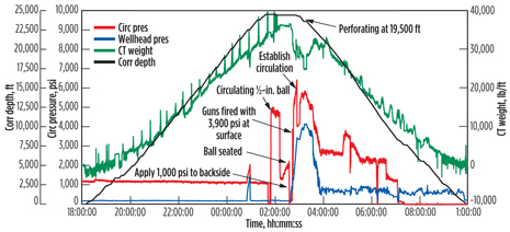
Fourth run: Perforating with TCP guns. The BHA was rebuilt, and the CT was then run in hole to 19,500 ft, and a 7/16-in. ball was once again circulated. After the ball seated, 500 psi were applied to the CT-tubing annulus. The CT was then pressured to 3,900 psi, as shown in Fig. 4, and the TCP guns were fired. Circulation was established down the tubing and up the casing, and the choke was manipulated to maintain WHP at 4,000 psi to keep the casing fluid from swabbing into the tubing. With CT at 18,000 ft, the WHP was bled off in 500-psi increments. The casing and tubing pressures were nearly equal, despite an expected 3,450-psi hydrostatic pressure in the casing. The CT was then pulled out of the hole, while 500 psi were held on the choke.
 |
| Fig. 4. CT post-job acquisition data plot for Run #4. |
|
Bullheading intermediate and top-cement plugs. The operator changed the job procedure to pump the intermediate and top cement plugs from the surface (not through the CT) after the fourth CT run. Casing fluid (32 bbl) was circulated back to surface before pumping the intermediate plug, with all returns being composed of seawater. The operator also decided not to perform the fluid swap that was originally planned to minimize mud returns at the surface. Instead, the operator recirculated the casing fluid, when pumping the intermediate plug from surface. When the cement (13 bbl) had been mixed and pumped, drilling mud was seen in the return tanks at surface. As the mud mixed with the seawater returned to the tanks, the fluid became difficult to pump, because the suction line became clogged and the fluid pump began to cavitate. Fresh seawater was pumped to complete the displacement for the operation, and a total of 100 bbl of drilling mud was disposed of at surface, which was 85 bbl more than planned.
RESULTS
The main objective of this operation was achieved without any HSE incidents. The job was successfully completed in 27 days at a much lower cost than if a conventional rig had been used. The CT cleaned out the well to 22,610 ft and was used to successfully place the bottom cement plug. One additional CT run was necessary to pump a second cement plug, as the original bottom cement plug could not be pressure-tested. The CT was also used to perforate the production tubing at 19,500 ft. These CT operations enabled the installation of two additional cement plugs required by regulatory agencies to be bullheaded, and allowed the operator to finally move forward with permanent abandonment of the well.
LESSONS LEARNED
For high-temperature services above 350°F, the BHA should be redressed after every run to minimize the risk of O-ring failure downhole. The pressure test, of the break in the pressure control stack, should include a pressure test of the CT connector and dual-flapper check valves by pressuring up, down the kill line, instead of down the CT string.
Another lesson learned was that the pumping of oil-based mud, contaminated with seawater, should be avoided to prevent damage to the fluid pumps. In addition, the job planning and coordination between the Schlumberger CT and cementing segments, the CoilTOOLS coiled tubing intervention tools and solutions, the Schlumberger New Orleans Technology Center, the InTouchSupport.com online support and knowledge management system were critical to the success of the operation. Quality control of the cement slurry design, mixing, and pumping was also very important in completing the operation’s main objective.
CONCLUSIONS
The team reached the following conclusions after evaluation of the P&A project:
- CT cementing operations, with a 1½-in. CT string, can be executed successfully at depths exceeding 22,000 ft and BHSTs approaching 425°F
- Conventional O-rings can be used in CT BHAs, provided the exposure time is kept to a minimum
- CT is a valuable P&A tool that can help reduce overall abandonment costs by providing a reliable, efficient alternative to wireline dump-bailing and rig cement-bullheading techniques
HPHT CT cementing operations require rigorous design, testing and planning, as compared to conventional CT interventions. 
|
DECOMMISSIONING IN THE NORTH SEA
ZIRCOSOL solvent cleans a Pb-210-contaminated heat exchanger
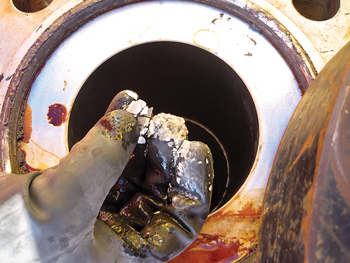
A North Sea operator faced the challenge of decommissioning a stainless steel heat exchanger on a gas production platform 70 mi northwest of Den Helder, The Netherlands. The heat exchanger, consisting of multiple, small-diameter stainless steel tubing connected to an 8-in. diameter manifold, was contaminated with radioactive Pb-210 scale.
Naturally occurring radioactive material (NORM) can result from co-precipitation or electrochemical deposition of radioactive elements, including radium, polonium and lead. NORM deposits usually take the form of mineral scale such as barium/radium sulphate or elemental metallic lead.
With management of NORM and other contaminants continuing to be an ever-increasing challenge for operators, conventional solutions, such as high-pressure water jetting typically fail to address all decontamination issues.
M-I SWACO has developed its ZIRCOSOL solvent as part of the EXKAL service line that includes comprehensive chemical technology solutions, in addition to specialist expertise to help operators deal effectively with scale and other deposits that can obstruct production or abandonment operations. The ZIRCOSOL solvent is a unique chemistry designed to efficiently and safely remove radioactive metal deposits from NORM-contaminated equipment through a simple static soak process.
Because of the heat exchanger tubing construction, removal of Pb-210 was not mechanically possible. HSE considerations and economics ruled out decontamination onshore. The operator invited M-I SWACO to propose a solution.
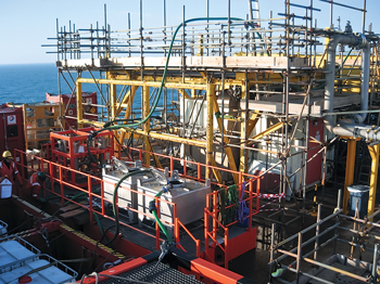
In compliance with legislation governing working standards for heights, the M-I SWACO team set up the proprietary bund tank system, complete with handrails and access/egress steps as close to the heat exchanger as possible. The closed loop system was leak tested and then filled with the ZIRCOSOL solvent, which was pumped through the entire heat exchanger bank to contact all internal surfaces of the exchanger. The dissolver was allowed to soak for a specified amount of time. Approximately 200 l of dissolver was pumped through the closed loop system every couple of hours to remove any potential air caps that may have been generated, as the scale was being dissolved.
Both of the heat exchanger banks were decontaminated and rendered free of Pb-210. This enabled the safe removal of the heat exchanger banks, which were then shipped onshore for safe disposal in compliance with local environmental regulations. As such, the ZIRCOSOL solvent enabled the efficient, safe removal of radioactive metal deposits in the heat exchanger that could not be cleaned by mechanical means. 
|
|
| Pb-210 containing scale (top) in a heat exchanger was dissolved through a proprietary ZIRCOSOL solvent injected through a closed loop treatment design (bottom). |
|
|
ACKNOWLEDGMENT
This article is adapted from Brendon Webb et al, “Plug and abandonment of a deep high-pressure and high-temperature Gulf of Mexico well using coiled tubing: A case history,” paper SPE 163942 presented at the SPE/ICoTA Coiled Tubing & Well Intervention Conference & Exhibition, 26-27 March, 2013, The Woodlands, Texas, USA.
REFERENCES
1. Rivas, O., Cementing through coiled tubing Level II, Schlumberger Well Services Training Center, 2007.
2. Larsen, H.A., A. Kenrick and R. Bell, “Utilizing coiled tubing in Mobile Bay’s 22,000-ft TVD gas wells yields economical and technical advancements,” paper SPE 38423, presented at the SPE/ICOTA North America Coiled Tubing Roundtable, Montgomery, Texas, April 1-3, 1997.
3. “Well Services QHSE Standard 22,” Coiled Tubing Operations, version 3.14, Schlumberger Well Services HSE Manager, 2012.
|
The author
ALEXANDER RUDNIK is a coiled tubing technical manager with Coil Tubing Services, a Schlumberger company, based in Houston. He has 20 years of experience in coiled tubing, matrix acidizing, and cementing. Mr. Rudnik holds an MS degree in mechanical engineering from Bryansk State Technical University, Russia.
BURT BONIN is a senior sales engineer for Coil Tubing Services, based in Lafayette, La. He has 30 years of experience in drilling and completions, coiled tubing, matrix acidizing and cementing. Mr. Bonin joined Schlumberger in 1992 and has been through a number of field, sales, and managerial positions working exclusively in the Gulf of Mexico.
BRENDON WEBB is a sales engineer with Coil Tubing Services, based in Anchorage, AK. Mr. Webb joined Schlumberger in 2005 and has worked in field and managerial positions in Texas, West Virginia and Louisiana prior to his current assignment in Alaska. He received his BS degree in chemical engineering from the University of Michigan.
LUKE LEFORT is a fluid technical engineer with Schlumberger, based in New Orleans Louisiana. He has eight years of experience, concentrated in well cementing. Mr. Lefort received his BS degree in chemistry from Nicholls State University.
|
|


