Innovative test methods in the lab and at the wellsite were used to evaluate the effectiveness of foam control products.
Jonathan J. Wylde, Clariant Oil Services
In heavy oil leases such as in Northern Alberta, crude oil ranges 10–14°API and has a large foaming potential and unique foam formation mechanisms. At a typical wellsite, heavy crude is heated in storage tanks to break out the gas, resulting in a thick and persistent foam in the top of the tank. This article reviews the literature on foam formation mechanisms and control methods, both mechanical and chemical. A unique laboratory test method is described that mimics the foam formation environment in the field. Field trial evaluation as well as the criteria for success and failure and some examples of the highest- efficacy products are discussed. Particular focus has been given to non-silicone chemistries, as silicone antifoam products are becoming less acceptable in environmentally sensitive areas.
FOAM FORMATION THEORY
Dissolved natural gas is always associated with crude oil production. In the reservoir, this mixture behaves as a single liquid phase at equilibrium with reservoir conditions. As crude oil is produced, depressurization causes degassing and, when combined with agitation, a dispersion of gas in the crude can be formed; the resulting colloidal system is termed foam.1
An ideal production process would result in the removal of all gas associated with the crude; however, even after three stages of separation, it is not normal for the gas to be totally removed, and the Gas-Oil Ratio (GOR) can still be as high as 10–20 cu ft per bbl.
Foam formation potentially causes many operational challenges, including:
• Black, smoky flares
• Liquid pump cavitation2
• Gas carry-under into the oil and water system3
• Liquid carry-over into the gas system3
• Reduction of separator capacity.4
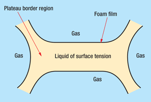
Foams are classified as colloidal systems with gas as the dispersed phase, and they characteristically have a very large interfacial area. A liquid foam is a two-phase system that consists of a three-dimensional liquid lamellae network that keeps the enclosed gas particles discrete from one another. Foam stability can be defined in terms of the strength and rheological properties of a thin, liquid film, Fig. 1. Drainage of liquid from the foam phase occurs through the plateau borders, and liquid is drawn into these regions by capillary forces. It has been proposed that one of the most important mechanisms of crude oil foam stability is the film elasticity.1
 |
|
Fig. 1. Idealized foam structure.
|
|
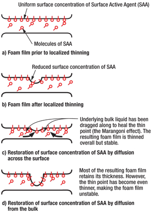
Natural surfactants present in crude oil, such as asphaltenes or short-chain carboxylic acids and phenols, can stabilize foams by adsorption of a surface-active compound at the gas-liquid interface, which lowers the surface tension.5 As liquid drains from the foam bubble walls, a resistance to thinning occurs, and therefore the surface tension increases. Surfactant migration occurs to compensate from a region of lower surface tension to an area of higher surface tension, resulting in restoration of film thickness and, thereby, stabilization of the foam. This is called the film elasticity effect or the Marangoni effect, Fig. 2. Foam stability is also enhanced by a viscosity effect that can occur either at the liquid surface or in the bulk phase, both of which restrict film drainage. On the other hand, crude oil foam decreases in stability as the moisture content increases.6
 |
|
Fig. 2. Film elasticity (Marangoni) effect.6
|
|
Foam breakdown occurs via three mechanisms:
Redistribution of bubble sizes. If a non-uniform gas bubble distribution exists, contact among these bubbles leads to gas diffusion from the small bubbles to the larger bubbles. This is because the gas pressure in the smaller bubbles is higher.
Film thinning. This is caused predominantly by gravity, which thins the top of the foam bubbles until the rigidity and strength of the walls is reduced to a point where the foam bubble collapses.
Film rupture. When a foam bubble collapses, the surface area of the droplets formed is significantly smaller than that of the original bubble. Due to the very large energy differential, a droplet may reach speeds of 10 m/s when a bubble bursts. These particles can collide with nearby foam bubbles and cause them to burst. A chain reaction therefore occurs that can enhance the overall foam breakdown.
FOAM CONTROL THEORY
Mechanical foam control concerns the internal structures within production equipment, such as the orientation and type of baffles, demisting pads and, especially, separator internals. A mechanical device can be installed on the separator inlet to enhance gas-liquid separation and minimize the formation of foam at the inlet of the separator. The device works by pre-separating the gas and liquid, thus dissipating the momentum generated at the inlet and reducing the likelihood of foam formation. Several case histories are available that describe how installation of process equipment has reduced the demand for chemical foam control methods.3,7
Foam control chemicals can be classified as either defoamers or antifoamers. A defoaming agent can be regarded as a surface-active agent that modifies the surface tension of a liquid.8 Antifoam agents, on the other hand, control the point at which foam bubbles nucleate in the bulk phase, and therefore suppress the formation of foam from the liquid phase. An antifoam will act by spreading over the gas-liquid interface, promoting local variation in the surface tension. If the film elasticity is unable to resist these variations, then the bubble will burst.
Most antifoaming agents are good defoamers, but, conversely, some defoaming agents are poor antifoams. The ideal antifoam agent is totally insoluble in water and has limited solubility in oil. It will also have a lower surface tension than the foaming medium. It will not be sensitive to temperature and will be resistant to chemical and oxidation attack. Furthermore, it will have good dispersibility in the continuous phase and have a low pour point.9
There are many commercially available products for defoaming and antifoaming. Examples of generic chemistry types are organic silicone and fluorosilicone compounds, phosphate esters, metallic soaps of fatty acids, sulfonated compounds, polyglycols, glycol ethers, amides and alcohols. The most common chemistry used in the oil industry tends to be the silicone-based products. The term silicone is generic and covers all organosiloxane polymers, such as PolyDiMethySiloxane (PDMS) and poly(methyl-3,3,3-trifluoropropyl) siloxane.
Non-silicone antifoams are becoming more widely used in the oil industry, especially in drilling and cementing applications. These types of antifoam have some advantages over silicone-based products. For instance, they are generally more biodegradable and therefore more environmentally acceptable for certain oil-producing basins. There are, however, convincing reports in the literature about the pervasity of silicones in the environment.10,11 Non-silicone antifoams are less likely to poison catalysts at refineries because they are less persistent and are thermally stable. In contrast, it has been stated that silicone remains in the oil phase and is used at too low a concentration to influence catalysts.12 One application in which silicone chemistry poisons downstream operations is in asphalt manufacture, where silicone antifoam cumulatively builds up in the process. Even small doses tend to keep the asphalt soft and do not allow it to achieve specification. The silicones tend to coat and build up on the top of fixed-bed catalyst reactors in the hydrotreaters of the fixed-bed hydrocracker, resulting in a scum layer in the plant that affects the quality of the final product and the efficacy of manufacture itself.
The obvious disadvantages of non-silicone antifoams are that they tend to be of lower efficacy and that they are more soluble in the crude, and therefore are more able to interact with the oil and other production chemicals.
EVALUATION OF CHEMICALS
Evaluation of products prior to field deployment is critical to ensure performance and compatibility. In Northern Alberta, an operator of a heavy oil lease comprising several hundred wells was experiencing production-inhibiting foam formation in the crude oil storage tanks. The wells typically used screw pump lift due to high solids production as well as the low API gravity and other oil properties, Table 1.
| TABLE 1. Summary of crude oil properties |
 |
The produced fluids passed through a 20–30-m flowline terminating in a pair of storage tanks, where the crude was heated from 50°C to 85°C. This heating caused gas breakout, resulting in the formation of a thick and persistent foam. The foam was able to enter the transportation trucks, ending up at the local tank battery and thus creating carry-over and separation problems in the process systems. Any antifoam deployed in this system could not contain silicone because these compounds poisoned the catalysts used in upgrading the heavy oil and in the manufacture of asphalt.
There was a need to bring a step change in performance of the foam control products. The previous incumbent products used included a phosphate ester and a salted amine. The phosphate ester product was a good antifoam agent, but the need to winterize the product to −40°C, through addition of methanol into the formulation, severely impeded the defoaming and antifoaming properties. The salted amine performed well as a defoamer, but as an antifoam it required injection rates as high as 715 ppm (volume).
Initial laboratory studies. Almost a dozen commercially available, non-silicone raw materials were tested in the lab with this Albertan crude oil after being formulated into a freeze-resistant matrix using combinations of methanol, 2-butoxyethanol and toluene.
The setup of the test equipment was a hybrid of the three methods described by Couget.13 The heavy oil was not recombined with its gas beforehand due to time limitations, as it takes up to three days to recombine the gas into the crude and each test consumes several liters of crude oil.
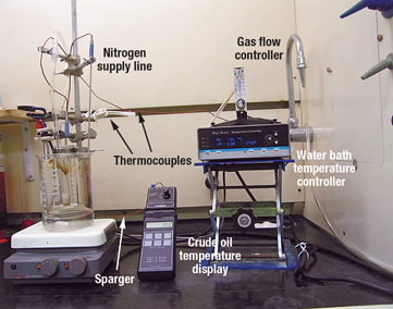
This particular crude oil would not create a significant foam in blank tests; therefore, heptane was added to simulate light (foaming) components in the crude and to artificially create a higher GOR. A 100-ml low-form graduated cylinder was immersed in a water bath in a 1,000-ml glass beaker. Heating was controlled via a power distributor with digital readout, an immersible heating rod and thermocouples. The water bath was placed onto a stir plate, and the whole assembly was secured with rods and clamps. Nitrogen gas was introduced to the base of the graduated cylinder via a coarse sparge tube, and flow was regulated by controlling the cylinder regulator, and finely controlled using a gas flowmeter to ensure valid repeatability, Fig. 3.
 |
|
Fig. 3. Laboratory screening test equipment.
|
|
The water bath beaker was stirred constantly with 40 ml of crude oil in the graduated cylinder. Once the oil had achieved the desired temperature, gas was flowed at 0.2 L/min. until a constant-height foam head formed. This level was maintained and recorded for 3 min. To test for defoaming properties, each chemical was injected at specific concentrations by gently sweeping the pipette to the side. The timer was started, and the foam drop recorded at 1-min. intervals until foam stopped dropping or maintained a level. The gas flow was then stopped, and 5 min. elapsed until the gas was reapplied to observe the return foam rate. After each test was completed, a thorough cleaning process was applied to prevent carry-over of antifoam from the previous test.
All tests were dosed with 400 ppm (volume) for both initial defoaming properties and subsequent antifoam testing. This dose rate was selected based on the average incumbent antifoam field injection rate.
Onsite testing. The laboratory testing described above validates whether or not a product is suitable for application in the heavy oil—i.e., whether it is suitably dispersible and compatible—and can effectively rank products. Additional onsite tests can be performed on fresh, non-aged crude oil within minutes of removal from the flowline sampling point, therefore precluding the requirement for addition of heptane.
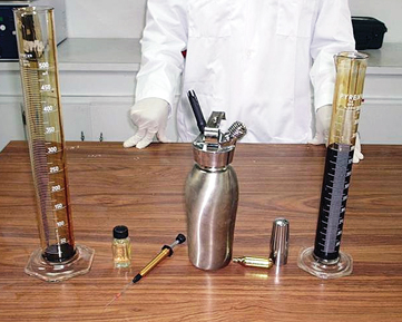
In the Alberta case history, due to the nature of the extremely heavy crude oil, a quantitative test was challenging to perform. The only way to make foam was by using compressed gas mixed in a pressurized cylinder with the crude. The foam was formed by forcing this mixture through a small orifice, thus allowing the production of about 1 L of foam from 500 ml of crude. Foam was produced with a pressurized whip-cream cylinder using carbon dioxide from seltzer chargers. The 500 ml of crude was sampled directly into the cylinder and pressurized using one seltzer charger, shaken, and kept warm on the water bath. Measuring cylinders of 250-ml volume were filled with foam, and the test chemical was added to the top of each beaker, Fig. 4. After 10 min., the content of the beakers was gently stirred, and defoamer action was observed.
 |
|
Fig. 4. Onsite field testing equipment.
|
|
The onsite testing confirmed the initial laboratory observations but ranked the relative performance of the best products much more closely than did the lab testing, where performance differed significantly.
FIELD APPLICATION OF ANTIFOAM CHEMICALS
Two chemicals were trialed in the field in Alberta. Two types of trial were performed: a) a defoamer application that involved batch treating a 1-gal pail of product directly into the storage tank and b) continuous injection into the flowline to evaluate antifoam properties.
A sodium sulfosuccinate salt was trialed first, and it provided excellent defoaming when using 1-gal batches. The product performed successfully as an antifoam when injection was optimized at 200–250 ppm. A 25% solids dispersion of long-chain fatty alcohols in water was trialed a few weeks later, and its defoaming performance was nearly identical to that displayed by the sodium sulfosuccinate; when used on a continuous basis it was marginally superior. Consideration was given to other blends being used at an increased application rate, but cost precluded field trial of these chemicals.
CONCLUSIONS
There are both mechanical and chemical methods of foam control, but effective treatment often requires a combination of the two. When testing for an effective antifoam chemical prior to field implementation, it is critical to test in an appropriate and representative manner. Exemplified by the above case history, the following conclusions can be drawn regarding testing of antifoam products:
The initial laboratory testing showed that inducing foam in heavy, aged crude was very challenging and the addition of heptane was successful in artificially foaming the crude oil. Lab tests also showed both the incumbent antifoam products to be poor performers, and identified a sodium sulfosuccinate salt and a long-chain fatty acid dispersion as the top two performing products.
The follow-up onsite antifoam testing showed that foam could be induced without the addition of heptane by using a seltzer cylinder in a semi-quantitative manner to rank performance of products against one another. Testing confirmed the initial laboratory testing insofar as the same two products performed the best out of all the products tested, but this testing showed a closer performance profile than in the offsite lab testing.
The subsequent field trial showed that onsite testing much better approximated the performance in the field. Wherever possible, onsite testing using the method described here should be performed to allow more confidence going into a field trial. 
LITERATURE CITED
1 Callaghan, I. C. and E. L. Neustadter, “Foaming crude oil: Study of non-aqueous foam stability,” Chemistry and Industry, 1981, pp. 53–57.
2 Fallin, S., Sharp, S. P. and J. L. Wolfe, “Defoaming agents for increased oil production rates of foamy crudes: Laboratory screening tests and field results,” Journal of Petroleum Technology, 23, No. 2, February 1971, pp. 233–238.
3 Wylde, J. J., Williams, G. D. M. and R. Cousins, “Unlocking the potential: A North Sea heavy oil success story,” SPE 97772 presented at the SPE International Thermal Operations and Heavy Oil Symposium, Calgary, Nov. 1–3, 2005.
4 Cassani, F. et al., “Evaluation of foam inhibitors at the Jusepin oil/gas separation plant, El Furrial Field, Eastern Venezuela,” SPE 23681 presented at the SPE Latin America Petroleum Engineering Conference, Caracas, Venezuela, March 8–11, 1992.
5 Callaghan, I. C., McKechnie, A. L., Ray, J. E. and J. C. Wainwright, “Identification of crude oil components responsible for foaming,” SPE Journal, 25, No. 2, April 1985, pp. 171–175.
6 Callaghan, I. C., Gould, C. M., Reid, A. J. and D. H. Seaton, “Crude-oil foaming problems at the Sullom Voe Terminal,” Journal of Petroleum Technology, 37, No. 12, December 1985, pp. 2211–2218.
7 Chin, R. W. et al., “Chemical defoamer reduction with new internals in the Mars TLP separators,” SPE 56705 presented at the SPE Annual Technical Conference and Exhibition, Houston, Oct. 3–6, 1999.
8 Garret, P. R., Defoaming: Theory and Industrial Applications, Marcel Dekker, New York, 1993.
9 McGhee, J., “Selecting chemical defoamers and antifoams,” Chemical Engineering, 96, No. 4, 1989, pp. 131–135.
10 Watts, R. J. et al., “Fate and effects of polydimethylsiloxanes on pilot and bench-top activated sludge reactors and anaerobic/aerobic digestors,” Water Research, 29, No. 10, 1995, pp. 2405–2411.
11 Xu, S., Lehmann, R. G., Miller, J. R. and G. Chandra, “Degradation of polydimethylsiloxanes (silicones) as influenced by clay minerals,” Environmental Science and Technology, 32, No. 9, 1998, pp. 1199–1206.
12 Pape, P. G., “Silicones: Unique chemicals for petroleum processing,” Journal of Petroleum Technology, 35, No. 6, June 1983, pp. 1197–1204.
13 Couget P., “Laboratory test performance methods for additional products used in petroleum production processes,” SPE 5298 presented at the SPE Oilfield Chemistry Symposium, Dallas, Texas, Jan. 13–14, 1975.
|
THE AUTHOR
|
 |
Jonathan Wylde earned a BSc degree with honors in geology and a PhD degree at the University of Bristol in the UK. Dr. Wylde joined Clariant Oil Services in 2002, initially working in the scale team of the R&D Center in Aberdeen, UK. Over the next four years, he managed the production chemistry on several major North Sea assets. He recently became the Business Manager for Clariant Oil Services Canada based in Calgary, Alberta.
|
| |
| |
|
|


