JAMEEL RAHMAN, CLIFFORD ALLEN and GIREESH BHAT, Halliburton
Advances in exploration and seismic imaging technologies have opened up new opportunities for large, deepwater field developments in the Gulf of Mexico (GOM), offshore Brazil, Asia-Pacific and offshore West Africa. The Lower Tertiary Wilcox trend of the GOM, alone, has seen over a dozen industry discoveries with world-class reserve potential. These are predominantly subsalt reservoirs at 5,000–10,000-ft water depths, with reservoir pressures over 25,000 psi at true vertical depths of 25,000 ft to 33,000 ft. Reservoir temperatures are in the range of 250°–300°F.
With a broad range of heterogeneous reservoir gross intervals from 1,000 ft to 3,000 ft and permeability ranges of 2 mD to over 50 mD, these fields may not be efficiently developed with the well completion technology used in today’s GOM, offshore Brazil, etc. Most of today’s completion tools are not designed for the pressure and temperature service of these deepwater and ultra-deepwater fields. The current lower completions system cannot provide adequate stimulation for these formations, while the present upper completions configurations do not provide an effective and reliable downhole zonal flow control, and surveillance for reservoir management.
To match or exceed published reserve recovery predictions from the Lower Tertiary trend, a new generation of integrated upper and lower completions technology will be required. This technology must incorporate effective asset surveillance techniques that can detect key well-performance indicators required by asset teams to optimize reservoir recovery and deliver higher returns for investors. The integrated solution must be scalable, reliable and intervention-friendly.
The performance envelope of the ICV is typically one of the weakest links in an intelligent completion. A second-generation ICV has been developed by evolving the design philosophy of the first-generation ICV, which was a joint-industry initiative developed by three major operators.1,2 Through changes in critical design and material specification, the second-generation ICV is expected to be easily adaptable to high-pressure, high-temperature (HPHT) and extreme environmental service required by the reservoirs of the Wilcox trend and other offshore locations. The design changes also ensure that the second-generation ICV improves operational efficiency and inflow performance.
ICV DESIGN
ICVs are designed to provide remote zonal flow control by choking, permitting or preventing fluid production into or out of a select reservoir. Unlike other downhole tools, ICVs may be required to move under conditions of significant pressure loading or unloading. They must be robust and reliable without compromising ease of intervention.
Conventional downhole sleeve seals are designed to handle a range of differential pressures between the well tubing and annulus. Intelligent well ICVs also require seals to manage differential pressures between the tubing and annulus, but additional considerations must be made for differential pressure interfaces between the ICV hydraulic chambers. The hydraulic chamber usually contains a fluid with a different specific gravity from the fluids in the well tubing and annulus, which results in differential pressures 1) between the tubing and annulus; 2) between chamber close-side pressures and tubing pressures; 3) between chamber close-side pressures and annulus pressures; 4) between chamber open-side pressures and tubing pressures; 5) between chamber open-side pressures and annulus pressures; and 6) between chamber close-side and chamber open-side.
The gross rating of the valve is defined by the differential pressure that the valve can handle between the tubing and annulus. All other interfaces are typically designed to a higher rating. In general, an ICV design should maintain a pressure balance during the operation to ensure performance integrity, and have quantifiable flow characteristics. Also, sealing technology must handle all loading and unloading scenarios for the life of well operations, and tension and compression integrity of the completion should be maintained.
First-generation valve design. The first-generation ICVs evolved from the sliding-sleeve technology. The design comprises a top sub, the balanced hydraulic piston, upper seat assembly, lower seat assembly (with the valve flow trim) and the bottom sub-assembly. The top sub provides structural integrity and houses the hydraulic piston chambers. Differential pressure application across the hydraulic piston actuates the movement of the upper seat assembly. This disengages the upper seat from the lower seat, and allows for fluid flow and communication between the annulus and tubing. The flow trim has a flow profile cut into it to provide the desired flow characteristics. In a fully closed position, a locking key mechanism for the upper seat and a reinforcing boost piston assembly for the lower seat create a pressure-tight radial line seal that helps maintain sealing capability under high differentials. Hydraulic pressure is applied through control lines to either side of the hydraulic piston to move the valve in either direction, Fig. 1.
 |
| Fig. 1. First-generation interval control valve. |
|
Design limitations. For the first-generation valves, a significant difference exists in the outer diameters (ODs) of the upper and lower seats, Fig. 2. This difference has a significant impact on the ability of the mandrel to be pressure-balanced along its length, especially at the seal line, creating opposing and unequal forces on the two seats when in the fully closed position. A locking key mechanism in the upper seat assembly, and a boost piston in the lower seat assembly, are required for reinforcement, adding additional components to the design.
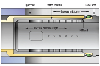 |
| Fig. 2. Seal alignment in first-generation valves. |
|
Upon activation, the upper seat travels across the OD of the ported flow trim, exposing the MTM seal face to pressure drops.
The MTM seal contact in these valves is a radial line seal that is vulnerable to debris. The upper seat is differential pressure-limited and cannot support higher differential pressures (15,000 psi, etc.) without having bigger dimensions than would be applicable for most wells. Increasing the strength of materials does not effectively improve the differential-pressure sealing rating on this design.
Second-generation valve design. The second-generation valve design maintains most components of the first-generation valves, with modifications made mainly to the upper seat and lower seat configuration. The upper seat mandrel travels inside the internal diameter (ID) of the ported flow trim and lands in a recess profile beyond the MTM seal face, Fig. 3. This enables the design of the upper seat to be of constant OD and creates a continuous cylindrical lineation for the upper and lower seat at the point of MTM contact. The constant OD minimizes development of opposing forces and creates a pressure-balanced mandrel, eliminating the need for additional mechanical support in maintaining the MTM seal. This design improvement negates the need for a locking key mechanism and the boost-piston assembly used in the first-generation valves.
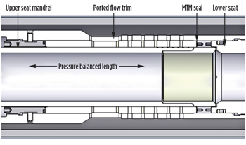 |
| Fig. 3. Seal alignment in second-generation valves. |
|
The MTM seal created by the upper seat inside the lower seat is a radial face contact seal, improving sealing capability. It also improves operational efficiency during initial opening of the valve, while the recess profile allows for better handling of wellbore debris in what may be referred to as the valve’s radial self-cleaning feature. Based on this design, changing to an appropriate material can readily improve the pressure rating of the valve without changing the dimensions. The pressure-balanced design also prevents drifting from its given position, owing to high flowrates and/or pressure fluctuations. The simplification of the design also allows for the inclusion of an optional position sensor in the ported housing of the valve, Fig. 4, a capability that the first-generation valve did not have.
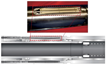 |
| Fig. 4. Position-sensor assembly. |
|
Design limitations. The design challenge for the second-generation ICV is the elastomeric seals inside the hydraulic chamber. Currently, the elastomeric seals are qualified to 15,000 psi and 330°F. Future focus will be on improving the ratings for ultra-high-pressure and temperature applications. Once seal stacks are qualified to ultra-high pressures, using a single-size envelope and changing only metallurgy, a range of high-pressure capabilities will be possible.
DESIGN QUALIFICATION
Project leaders often associate new tools or technology with additional sources of project risk. Effective project management requires early identification of these risks. For downhole tools, the risk of applying new tools or technology is particularly high, especially in deepwater environments, where addressing a downhole failure is very expensive. A good qualification program has to demonstrate the ability of a new tool to perform above design specifications and also be suitable for field use.
Qualification of new technology is a systematic process aimed at reducing risk, increasing the probability of success, and ensuring fit-for-purpose status before going into operation.3 The systematic process used took into account experiences from intelligent well-failure mode effects analysis (FMEA), root-cause analysis (RCA), and downhole tool operations to prepare the qualification program of the second-generation ICV. The goal of the qualification program was to identify all significant failure modes associated with system-specification performance and service-operation performance phase.
Seven steps can be used to fully describe the systematic process of new-tool qualification:
-
Build a multi-disciplinary team ofsub-system and system experts, system users, etc.
-
Profile system, sub-system and component levels of ICV, and define functions.
-
Define performance expectations for various phases of service (installation, operations and intervention).
-
Identify all failure modes associated with system and field-service application.
-
Define actions to be taken to qualify performance, as per design specification and service operations.
-
Carry out qualification tests to demonstrate the capability of the design.
-
Quantify the gross rating of the system, sub-system ratings, operating specifications, etc.
The design phase of any new tool starts with identifying potential failure criteria, using the FMEA analysis. Following the designed FMEA, a qualification process flowchart is used to identify and define testing criteria for the tool, Fig. 5.
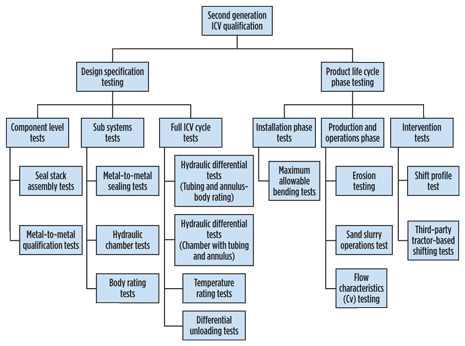 |
| Fig. 5. Qualification process flowchart. |
|
The flowchart shows two categories of tests. The first category is designed to qualify system performance of the components, both sub-systems and full-system level. A second category of tests is used to qualify system performance for service through simulation of three phases of field service: installation, production operations and intervention. This generated a number of qualification tests:
Life-cycle testing. Life-cycle tests are conducted to qualify the valve design to harsh cyclic loading conditions. These tests are conducted to verify mechanical performance of the ICV and the MTM and dynamics seals under long-term repeated loading.
The qualification program consisted of operating the valve to various combinations of temperature, pressure, and axial loads, as well as operating the sealface at several fluid differentials. It consisted of static internal, external, as well as hydraulic pressure-tests to 10,500-psi differentials with water and gas at ambient temperature and at 330°F, while operating the valve at 5,000-psi fluid differentials across the trim. Upon successful completion, the test was then repeated at axial load cycles of 170K tension and compression. At its harshest, the tool was subjected to repeated operating sequences of 10,500-psi pressure differentials at 330°F, and 170K tension and compression cycles. Upon successful completion, the test was repeated to reconfirm qualification.
Hydraulic seal-stack assembly qualification. The hydraulic seal stacks were subjected to pressure differentials of 11,000-psi dry gas for an alternating regime of 1,100 operating cycles at ambient and 325°F temperature cycles. This test was repeated with 600 operating cycles and Canning HW443 fluid at ambient temperature and 325°F. Gas-leak checks were performed intermittently throughout the test cycle to confirm bubble-tight sealing capability of the packing design. Under a different setup, the seal stacks were also subjected to 260 operating cycles at ambient temperature and 285°F for a full-fluid differential of 15,000 psi.
MTM seal qualification. The MTM seal qualification program involved an alternating regime of multiple open-and-close strokes at ambient temperature and at 330°F, respectively, cumulating to a total stroke count of 500 cycles. Successful fluid-differential tests of 15,000 psi were performed at each temperature change. The program also included seal unloads every 50 strokes at an industry-highest differential of 5,000 psi across the MTM seal. A liter of fluid was also flown across the sealface at each unload. Upon successful completion, this regime was repeated once more to fully qualify the MTM seal.
Sand slurry and erosion tests. Sand slurry testing is conducted to evaluate the reliability and repeatability of valve operations when subjected to debris-filled environments, Table 1. Tests were conducted, based on API 14A, SCSSV Class II sand slurry debris test requirements to qualify the second-generation valves. Sand slurry consisting of gelled water with 80–100-mesh sand with a slurry viscosity of 70 +/- Marsh-seconds and a sand content of 2% (+/- 0.5%) was circulated through the valve in several flow sequences. Operational and tubing tests to 5,000 psi were conducted after each flow period to verify the integrity of the valve.
| Table 1. Sand-slurry characteristics. |
|
|
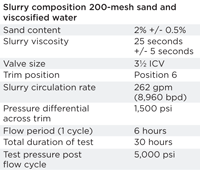
To evaluate erosion and quantify the MTM seal integrity after sustained sand-slurry flow across the trim, erosion tests were conducted at our erosion test facility in Duncan, Okla. The tool was subjected to 2% by weight, 200-mesh sand flown across the trim at position 6, at a flowrate of 6.5 bpm, at a pressure differential of 1,500 psi. The flow period included multiple cycles of 6-hr increments. Tubing-pressure tests were conducted at each flow interval, and successful tests were obtained. Acceptable leak-rate criteria of less than 10 cc/min (based on API 14A) were also satisfied.
Flow coefficient (Cv) test. This test was conducted to determine the flow coefficient (Cv) values and to quantify the flow characteristics as a function of choke travel and pressure drop on either side of the choke under controlled flow conditions. The method for calculating Cv for the valve was adapted from the ANSI/ ISA- 75.02-1996 specification. The Cv and the flowrate are related, as given by Eq. 1.
 |
Eq. 1. |
Where;
Q = Flowrate in gpm
R = Specific gravity at upstream conditions (density of liquid at flowing temperature to density of water at 60°F)
P1 = Upstream absolute static pressure measured in two nominal pipe diameters upstream of valve fitting
P2 = Downstream absolute static pressure measured in six nominal pipe diameters downstream of valve fitting.
Bend test. To address dog-leg severity issues in wells, bend tests were conducted on the second-generation valves with an applied load at the center of the valve, which is supported only by stands at the far ends of 30-ft tubing joints made up to the valve. The center load induced a bend in excess of 10°/100 ft at the center of the valve. The valve was then stroked in this condition for a total of 25 cycles, following which it was disassembled and observed for any galling. It was reassembled and stroked again several times to ensure no damage had occurred from stroking in a bend condition. The valve was qualified for operation in an industry-standard bend severity of up to 10°/100 ft.
Mechanical shifting tests. Consistent with first-generation valves, the second-generation valves have the ability to be mechanically shifted in case of a loss of integrity of the hydraulic circuit in the installation. This can be achieved with coiled tubing or wireline-based shifting tools. Several shift cycles were conducted with the shifting tools to verify this functionality. Further successful tests were also conducted, with third-party, wireline-based tractor and shifter tools to verify this functionality.
APPLICATIONS
Aside from the improved pressure and temperature ratings, the design improvements of the second-generation valves have improved the efficiency of completion operations and global applications for intelligent completions.
Operational improvements. Owing to a true pressure-balanced mandrel design, eliminating the need for extra components for the latching and boost mechanism, the long-term success-rate probability has increased, as additional potential failure points have been eliminated from the design. In addition to the change in the MTM sealing mechanism and the self-cleaning seal design, the second-generation valves have a much higher debris tolerance than the first-generation valves, which eliminates the current practice with first-generation valves to cycle the valve and flush debris across the trim during the run-in-hole phase of the installation program, thereby saving much valuable rig time. Also, as a result of design improvements, the second-generation ICVs have applications beyond the pressure limitations of the first-generation ICVs.
Global installations. As of June 2012, hundreds of second-generation valves have been supplied to operators around the globe, of which 147 valves have been installed in 50 wells. All of the installed valves are fully functional to date, and there have been no reported failures of any of these valves under well operating conditions.
CONCLUSION
The application of a sustainable design with stringent qualification has resulted in a second-generation interval control valve poised to take on the requirements of service in deepwater, ultra-deepwater, and other harsh environments. Upon full qualification, the second-generation suite will contain valves in all sizes from 2⅞ in. to 5½ in., with a gross rating of 330°F and 15,000 psi. Following this, a program will be initiated to start qualification of the hydraulic seal stack to higher pressures and temperatures in order to keep up with industry demands. 
REFERENCES
1. Botto, G., C. Giuliani and B. Maggioni, “Innovative remote-controlled completion for Aquila deepwater challenge,” SPE paper 36948, presented at the SPE European Petroleum Conference, Milan, Italy, Oct. 22–24, 1996.
2. Robinson, M. C., and D. Mathieson, “Integration of an intelligent completion into an existing subsea production system,” OTC paper 8839, presented at the Offshore Technology Conference, Houston, Texas, May 4–7, 1998.
3. Hother, J., “Risk minimization by the use of failure mode analysis in the qualification of new technology,” SPE paper 96334, presented at the Offshore Europe Conference and Exhibition, Aberdeen, Scotland, UK, Sep. 6–9, 2005.
ACKNOWLEDGMENT
This article is based on SPE Paper 150850, prepared for presentation at the North Africa Technical Conference and Exhibition, Cairo, Egypt, Feb. 20–22, 2012. Used with permission.
|


