Offshore Report
Designer casing addresses needs of deepwater HP/HT wells
Special needs of high pressure, high temperature exploration wells in deep water justify development of custom-designed casing and related installation methods.
Michael L. Payne, BP, and Richard A. Miller and Peter Erpelding, Viking Engineering
Deepwater high pressure, high temperature (HP/HT) drilling environments present difficult challenges to well engineers. Typical deepwater pore pressure and fracture gradient profiles result in a narrow drilling window that may require 7 to 9 casing points. The high cost of these wells demands a high-rate completion for economic payback, which defines sizes of production casing and liners.
Drilling casings are restricted by the standardized 18-3/4-in. through-bore diameter dictated by high pressure wellhead housings, BOPs and riser systems. Further, high pressures require thick-wall casing, especially if sour service materials are specified. Satisfying all of these constraints requires some unconventional practices.
Current and emerging technologies offer several ways to address this design dilemma. Riser-less drilling can effectively delay running the high pressure wellhead, allowing for additional large-diameter casing seats. Dual-gradient drilling can decrease the number of required casing points. Solid expandable liners provide a way to add or push casing points without the geometry impact of a conventional string. And managed pressure drilling (MPD) may also show promise for eliminating a seat. However, heavy reliance on these new technologies may run counter to the guiding principle of keeping HP/HT wells as simple and reliable as possible.
This article, based on Paper SPE 97565,1 presents the concept of using conventional oil country tubular goods (OCTG) in unconventional sizes to increase the number of available casing points in deepwater wells. The method has several advantages in performance and reliability areas, compared with the above noted technologies. Decades of industry experience with conventional OCTG make the technology especially appropriate for containing high pressures and sealing off trouble formations.
Related issues such as manufacturing lead time, costs, connections and hangers are discussed. Several HP/HT examples illustrate the trade-offs with other design options.
INTRODUCTION
Typical Gulf of Mexico (GOM) deepwater exploration wells have these design constraints, ex.: 7 to 9 casing seats; an 8-1/2-in. minimum hole size at TD; and an 18-3/4-in. wellhead bore. Some prospects are further complicated by having more than nine casing points.
A representative GOM schematic is shown in Fig. 1, including two sour-service C-110 production liners and provisions for a production tieback. However, designing these production tubulars becomes a non-trivial task as pressures/ temperatures increase.
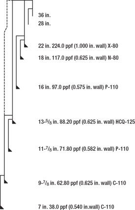 |
Fig. 1.Typical Gulf of Mexico deepwater exploration casing program with production liner and tieback.
|
|
For example, the 9-7/8-in. production liner has an API minimum internal yield pressure (MIYP) of 12,180 psi. Casing of the same OD and sour service C-110 material, but a nominal 15,000-psi rating, requires a wall thickness of 0.770 in., resulting in a drift diameter of 8.179 in. This adversely impacts subsequent bottomhole size and the lower completion.
This thick-wall 9-7/8 in. can be used for a production tieback, at the expense of tubing and safety valve size. The top portion of the tieback is commonly telescoped larger to accommodate safety valve and bypass lines; but 10-3/4-in. C-110 casing with a 15,000-psi MIYP has a drift diameter less than 9 in.
If field economics require a high-rate 5-1/2-in. or larger tubing completion, the well could be built from the inside out. The 9-7/8-in. production liner grows to 10-3/4 in., and the tieback has 11-3/4-in. casing at the top. However, these production tubulars do not fit easily inside the drilling casings of Fig. 1. These casings could also increase in diameter, but eventually the strings become too large to fit inside a standard 18-3/4-in. wellhead and BOP.
Further complications arise if the drilling casings have inadequate pressure ratings. Tight clearances afford little room to increase wall thickness.
Finally, the standard wellbore does not include a conventional contingency seat to combat adverse hole conditions or to address stability issues in a highly deviated development wellbore.
The standard casing program of Fig. 1 has accommodated deepwater GOM exploration for many years. But it is apparent that a non-standard approach is required to develop some of the deepwater HP/HT targets.
ENABLING TECHNOLOGIES
Several developing technologies may enable solutions to the deepwater HP/HT design challenge. These options are briefly mentioned to highlight opportunities and challenges, not to provide an exhaustive review of status or viability.
Solid expandable liners. A vast number of papers have publicized the development of expandable casing.2,3,4 The promise of gaining a casing seat without dropping hole size has encouraged a rapid acceptance of the technology. The growing experience base has led to a better understanding of how to use these products and improve job reliability.
Expandables could significantly ease the deepwater HP/HT design challenge by providing more clearance for conventional OCTG strings. However, several lingering obstacles prevent expandables from becoming the clear alternative for deepwater HP/HT casing design.1,5 These include: connection integrity, low post-expansion collapse ratings, increased rig time, limited running lengths and higher cost. Continued improvements to expandable technology are expected, but these challenges bring pause to relying on expandables to solve today’s deepwater HP/HT casing design dilemma.
Dual-gradient drilling (DGD). Typical deepwater drilling prospects have narrow windows between pore pressure and fracture gradient. The long water column impacts the magnitude of pressures when measured as a gradient relative to the rig. DGD can reduce a portion of the fluid gradient in the drillstring annulus.6,7 A heavier mud can be used to control BHPs without subjecting weaker up-hole formations to the same equivalent mud weight.
Riser-less “pump and dump” drilling is a special case of DGD where the annulus fluid column is seawater to the mudline, and weighted mud is in the drilled hole.
The benefit of DGD is a wider margin between pore pressure and fracture gradient when mapped to an equivalent mud weight basis with respect to the mudline, allowing longer openhole sections and fewer casing seats.1 The additional clearance can accommodate larger or higher-pressure strings, thereby solving the deepwater HP/HT design dilemma.
However, DGD with full well control equipment is an unproven technology. There are several technology gaps to solve, and the high up-front cost of rig conversion is an impediment to field testing the concept.1
Managed pressure drilling (MPD). This applies to any technique of controlling annular pressures while drilling. Technically, DGD is a type of MPD. Other types use a rotating control device to drill ahead with closed and pressurized mud returns,8 or an equivalent circulating density (ECD) reduction tool9,10 to reduce fluid friction impact while circulating.
The biggest benefit of MPD is to extend hole sections by either drilling underbalanced or by limiting annular pressures at weaker uphole formations. The longer hole sections may enable fewer casing points, thereby loosening constraints on the deepwater HP/HT design dilemma.
However, though forms of MPD are commonplace on land rigs, these technologies are largely unproven in the deepwater environment. The ECD reduction tool may improve hole stability and extend hole intervals; but well-control risks may be higher, and the tool has a detrimental impact on rig hydraulics. Significant tool development is required to gain what may only be an incremental benefit to well design.
Designer muds. Recent work in creating specialty muds shows promise for strengthening the wellbore, allowing higher mud weights without losing returns.11 Such muds have been used to drill through highly depleted sands without cutting mud weight. This “stress cage” technology may be extended to strengthen weak casing shoes, enabling longer hole sections and reducing the number of casing seats. Designer muds appear to be highly beneficial for specific limited-loss formations, but they may not be sufficient to solve the deepwater HP/HT design dilemma.
Custom OCTG. Purpose-built casing strings are hardly new. The API casing tables contain sizes that were once unique, such as 7-3/4-in. 46.10 ppf and 11-3/4-in. 65.00 ppf; and they lack many items that are commonly used, such as 9-7/8 in. 62.80 ppf and 13-5/8 in. 88.2 ppf. Sizes, weights and grades have been developed to address specific well needs, such as the 12-1/8-in. 90.0-ppf C-110 x 10-3/4-in. 73.0-ppf C-110 x 10-in. 72.0-ppf Q-125 intermediate casing used at Erskine – the first HP/HT well in the North Sea.12 There appears to be little news when it comes to custom OCTG.
The familiarity of custom OCTG is its strongest argument for using odd sizes to provide deepwater HP/HT design solutions. Drilling clearances and pressure ratings can be precisely optimized across all strings. An additional casing seat can be squeezed into the program, or special sizes can be built to accommodate higher pressures.
There are a few challenges in using custom sizes, primarily in the area of pressure isolation. Liner hangers and seals become critical, as do cement jobs through tight clearances. The benefits and challenges of custom OCTG will be further explored in detail.
THE CASE FOR CUSTOM OCTG
Designer casing strings are proposed as an alternative to the technologies listed above. It is the familiarity of custom OCTG that makes it most appropriate for deepwater HP/HT well design, where the priorities are to keep it simple, and make it reliable. The benefits of an established system are:
- OCTG is a mature, well understood technology.
- There is a wealth of reliability data to support downhole performance.
- Industry standards comprehensively govern manufacturing/ inspection.
- Custom connections can be extended from existing designs, simplifying acceptance qualification.
- Custom OCTG is compatible with liner drilling. Strings can be drilled in place. And liner rotation increases the chance of getting the liner to the bottom and assists cement placement.
Upgrade pressure ratings. The wellbore shown in Fig. 1 has proven useful for GOM deepwater exploration. However, it has its limitations when considering high-rate HP/HT or extreme HP/HT completions. Fig. 2 is a modification of the exploration well design. The same 22-in. and 18-in. strings are used, but the 16-in. casing is run back to the mudline and upgraded to an MIYP of 10,680 psi.
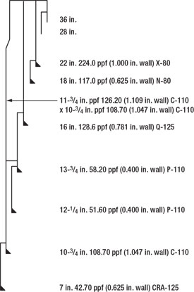 |
Fig. 2. Exploration well upgraded to accommodate 18,000-psi production tubulars and a 5½-in. completion.
|
|
Below the 16-in. intermediate casing are two custom liners sized to provide a half-inch clearance between their ODs and the previous casing drift diameter. The drilling/ production liner is upgraded to the heaviest wall 10-3/4 in. that maintains an 8-1/2-in. drift.
The wellbore in Fig. 2 uses designer strings to accomplish the following: 8-1/2-in. hole on bottom; production tubulars with an 18,000+ psi MIYP; 5-1/2-in. tubing; 9-3/8-in. upper tieback drift (for a safety valve). And clearance outside the tieback is provided for syntactic foam to mitigate annular pressure buildup (APB).13
The same features could be accomplished by running an expandable 13-3/8-in. x 16-in. liner below the 16 in., and then covering it with a conventional 13-3/8-in. drilling liner. The question becomes one concerning preferences; i.e., proven, reliable OCTG technology vs. emerging expandable technology; lower vs. higher cost; higher vs. lower performance; and shorter vs. longer rig time.
Add a shoe below 18 in. Designer strings could also be used to add a shoe to the standard exploration casing program. Fig. 3 shows a configuration that adds a shoe below the 18-in. casing. The 16-in. drilling liner is replaced by two custom sizes, a 16-3/8-in. liner and a 15-in. liner. The liners represent a trade-off between wall thickness for pressure ratings and ease of cutting connections vs. running clearances. Each liner and the subsequent 13-5/8-in. casing have a 0.387-in. clearance between the casing OD and the previous casing drift. This clearance is greater than running 11-7/8 in. inside 13-5/8 in. (0.375 in.). The two liners each have a 0.4-in. wall thickness for ease in cutting threads.
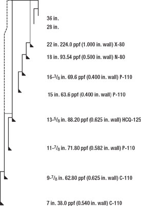 |
Fig. 3. Exploration well modified to add a casing seat below the 18 in.
|
|
A similar geometry could be achieved by running a 16-in. liner and a 13-3/8-in. x 16-in. expandable liner. However, the custom OCTG liners have improved internal pressure ratings – 4,700 psi for the 16-3/8 in. and 5,130 psi for the 15 in., vs. 3,420 psi for the expandable liner. The 15 in. has a drift diameter of 14.012 in. vs. only 13.811 in. for the expandable liner, thus the expandable may not accommodate a subsequent 13-5/8-in. string. These advantages for the custom OCTG liners are in addition to the general benefits listed earlier.
Add a shoe below 16 in. As a final example, custom OCTG is used to add a shoe below the 16 in. The wellbore in Fig. 4 has the same strings through the 16 in. A custom 14-1/4-in. liner is sized to provide 0.5-in. clearance between its OD and the previous 16-in. drift. The subsequent intermediate casing has the same 13-5/8 in. at the top, but the bottom is a custom 12-3/4-in. pipe sized to give similar ratings as the 13-5/8 in., while maintaining an 11.504-in. drift for the subsequent custom 11-in. liner. A 9-3/8-in. drilling liner is also included in this wellbore; the 9-3/8 in. is a good example of a size that was once custom, but is now becoming more common.
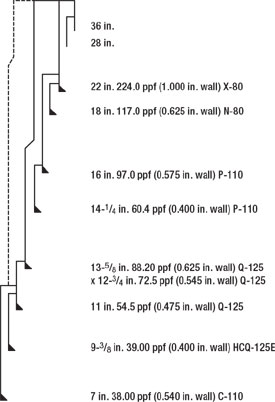 |
Fig. 4. Exploration well modified to add a casing seat below the 16 in.
|
|
This wellbore does not have clear geometric advantages vs. one that uses expandable liners. An expandable 13-3/8-in x 16-in. liner could replace the custom 14-1/4-in., and the intermediate casing could then be 13-5/8 in. x 13-3/8 in. The custom 11-in. liner provides significantly higher performance ratings compared to an expandable 11-3/4-in. x 13-3/8-in. liner. The three examples shown are not intended to be an exhaustive list of how purpose-built strings can solve deepwater HP/HT design issues. Rather, they are shown to raise awareness of the benefits of custom OCTG.
CRITICAL COMPONENTS FOR CUSTOM OCTG
Previous industry experience has demonstrated that rolling custom OCTG is easily achievable. Cutting threads on custom sizes is also a normal practice. A key, critical component for using designer casing sizes is a liner hanger that seals pressure, either by itself or with a subsequent liner top packer. The status of these related components is briefly described.
Custom pipe sizes. Custom OCTG can be manufactured using either a Seamless or Electric Resistance Weld (ERW) process. The seamless process involves piercing a hot cylindrical billet of steel, then running it through a series of sizing mandrels to produce the finished product. The ERW process involves forming the tube from a coil of flat plate steel, then welding the seam formed by the two edges. Both methods have distinct advantages and disadvantages, as explained further in the SPE paper.1
The steel market is highly volatile and strongly influenced by supply/ demand. Average price for a custom OCTG order in mid-2004 was $1.20/lb for P-110, and $1.30/lb for Q-125. This represented a premium when compared to standard-sized casing, but significantly less than the cost of expandable casing.
Connections. Connections can be threaded on tubulars with wall thickness as low as 0.4 in. without forming the pipe ends. For casing diameters greater than 16 in., additional wall thickness (» 0.425 in.) is required.
To help ensure that casing will meet drift requirements, steel mills generally roll casing very close to the upper limits of the +1% API OD tolerance. Variability in actual measured OD between various mills can lead to threading difficulties on thin-wall pipe. To overcome this hurdle, connection manufacturers typically swage the box and crimp the pin on tubulars that have a diameter to wall thickness (D/t) ratio greater than 30. Swaging allows the connection manufacturer to place the material where it is needed for threading.1
Connection performance for a swaged connection on custom OCTG is very similar to that of OCTG in standard sizes. The tension efficiency is about 70%, compared to the pipe body. These ratings are more than adequate for service conditions applied to drilling liners.
Custom connections can be developed with lead times of four months or less, when the size is a close extension of an existing design. Gauge equipment takes about six weeks to procure, as can the forming tools required to swage the connection.
Conventional liner hangers. As detailed further in the SPE paper,1 the liner hanger industry has some difficulty providing conventional liner hanger and liner top packer systems that can by used for casing strings with radial clearances of 0.25 in. or less. There is very little room to house the required components, while providing reasonable tension and differential pressure ratings. Achieving liner hanger/ packer systems for casing strings with radial clearances of 0.25 in. is not insurmountable, as 11-3/4-in x 13-3/8-in. 72-ppf liner hanger/ packer systems are well established in deepwater well design. Development of a custom hanger may take a year for detailed design, prototyping, testing and manufacturing.
It is critical that liner hangers are fully rotatable. This feature allows the liner to be rotated, or even drilled in place, provided that a high-torque connection is cut on the base pipe. Rotation will also help with cement placement and pressure isolation.
The next generation of conventional liner hanger systems represents a focused effort to improve the design and functionality of existing liner hanger technology. The key improvement is the use of a hydraulic setting tool to set the slips and packer components. This new system has also eliminated many of the potential pitfalls found in current conventional designs.
Expandable liner hangers. Expansion of the hanger into the base casing is a relatively new technology that provides a promising solution for hanging liners in tight clearances. An expandable hanger provides many benefits where other technologies fail. These include low clearance and high load applications. This technology has an added benefit in that the hanger and packer are both part of the same tool. This greatly simplifies the entire process, thus increasing the overall reliability of the hanger system.
The primary seal is the metal-to-metal interference developed between the expandable hanger and the base casing. A bonded elastomer can also be incorporated as a backup seal to the primary metal seal, but is not required. Expandable hangers are new, and some 80 have been run in conjunction with conventional OCTG pipe. These include: 5-in. x 7-in. and 7-in. x 9-5/8-in. hangers. The hangers can be rotated, allowing this technology to be compatible with casing drilling. Larger sizes are still being developed at R&D level.
Clearances and isolation seals. Tight clearances have been pushed for years.14 And 11-7/8-in. casing with flush connections have been routinely run inside 13-3/8-in. and 13-5/8-in. casing. This example of a 0.375-in. diametrical clearance between casing OD and the previous drift is used as a minimum bench mark.
Openhole running clearances are improved by drilling oversized holes, a common practice in the GOM. The enlarged hole increases the chance for a good cement job and the corresponding pressure isolation. A fully-rotatable liner hanger is key to assisting cement placement.
In addition, a couple of emerging technologies may provide alternatives to conventional cement and liner top packers. Swell packers may provide a way to seal the liner top without requiring clearance for mechanical devices. Polymer shut-offs may provide zonal isolation without the placement risk of a cement job through tight clearances.
These technologies are not considered hinge factors for making custom OCTG work, but they could become useful options for improving pressure integrity.
CONCLUSIONS
Deepwater HP/HT well design is a challenge to fit enough casing seats, between the constraints of an 18-3/4-in. wellhead and BOP and the bottomhole size required for a high-rate completion. Custom OCTG represents an enabling technology for solving the deepwater HP/HT design challenge.
There is nothing special about rolling custom pipe; connections are an extension of proven designs; liner hanger development is critical; and custom OCTG does not preclude development of other technologies such as liner drilling.
In addition, technologies such as managed pressure drilling, designer muds, and expandable liners, may also provide ways to satisfy the well design challenge. However, these technologies are at various stages of development, carrying significant risks and increased costs.
To expedite development, qualification and sourcing of custom OCTG, deepwater operators should work toward a short list of the most leverage-able sizes to encourage vendors to bring these products to the market. 
ACKNOWLEDGMENT
The authors thank the managements of BP for permission to prepare the original SPE paper and present the subject material to the industry. World Oil thanks BP for allowing the publication of this article version of the original paper, and the Society of Petroleum Engineers for granting permission for this important paper’s further publication.
LITERATURE CITED
1 Miller, R.A., M.L. Payne and P. Erpelding, “Designer casing for deepwater HPHT wells,” Paper SPE 97565, Presented at the 2005 SPE Applied Technology Workshop on High Pressure/ High Temperature Sour Well Design, The Woodlands, Texas, May 17 – 19, 2005.
2 Filippov, A., et al, “Expandable tubular solutions,” Paper SPE 56500, Presented at the 1999 SPE Annual Technical Conference, Houston, October 3 – 6, 1999.
3 Dupal, K.K., et al., “Solid expandable tubular technology – A year of case histories in the drilling environment,” Paper SPE 67770, Presented at the 2001 SPE/IADC Drilling Conference, Amsterdam, February 27 – March 1, 2001.
4 Gusevik, R. and R. Merritt, “Reaching deep reservoir targets using solid expandable tubulars,” Paper SPE 77612, Presented at the 2002 SPE Annular Technical Conference, San Antonio, Texas, September 29 – October 2, 2002.
5 ISO 13679, Procedures for testing casing and tubing connections, First Edition, 2002-12 – 15.
6 Schumacher, J.P, et al., “Planning and preparing for the first subsea field test of a full-scale dual-gradient drilling system,” Paper SPE 80615, SPE Drilling & Completion, Vol.17, No. 4, 2002, pp. 194 – 199.
7 Judge, R.A. and R. Thethi, “Deploying dual gradient drilling technology on a purpose-built rig for drilling upper hole sections,” Paper SPE 79808, Presented at the 2003 SPE/IADC Drilling Conference, Amsterdam, February 19 – 21, 2003.
8 Hannegan, D., “Managed pressure drilling in marine environments – Case studies,” Paper SPE 92600, Presented at the 2005 SPE/IADC Drilling Conference, Amsterdam, February 23 – 25, 2005.
9 Bern, et al., “ A new downhole tool for ECD reduction,” Paper SPE 81642, Presented at the 2003 IADC/SPE Underbalanced Technology Conference, Houston, March 25 – 26, 2003.
10 Bern, P.A., W.K. Armagost and R.K. Bansal, “Managed pressure drilling with the ECD reduction tool,” Paper SPE 89737, Presented at the 2004 SPE Annual Technical Conference, Houston, September 26 – 29, 2004.
11 Aston, M.S., et al., “Drilling fluids for wellbore strengthening,” Paper SPE 87130, Presented at the 2004 IADC/SPE Drilling Conference, Dallas, March 2 – 4, 2004.
12 Elliott, G.S., R.A. Brockman and R.M. Shivers III, “HPHT drilling and completion design for the Erskine field,” Paper SPE 30364, Presented at Offshore Europe 95, Aberdeen, September 5 – 8, 1995.
13 Payne, M.L., et al, “Advanced topics for critical service deepwater well design,” Presented at Deep Offshore Technology, Marseille, France, November 19 – 21, 2003.
14 Barker, J.W., “Wellbore design with reduced clearance between casing strings,” Paper SPE 37615, Presented at the 1997 SPE/IADC Drilling Conference, Amsterdam, March 4 – 6, 1997.
THE AUTHORS
|
 |
Michael L. Payne, PhD, a senior advisor for BP in its Exploration and Production Technology Group (EPTG), holds BS and PhD degrees in mechanical engineering from Rice University, an MS degree in petroleum engineering from the University of Houston, and executive education from the University of Chicago GSB. Previously an advisor for ARCO, he has 24 years’ drilling experience including operations, computing, technology and consulting. Dr. Payne has extensive industry publications, is chairman of the API Pipe Committee (SC5) and convenor of ISO SC5 WG2 and SC4 WG1. He serves on the board of the DEA, and has been recognized by SPE as a distinguished lecturer, and as the SPE International Drilling Engineering Award recipient for 2000.
|
|
 |
Richard A. Miller, a well engineering consultant through Viking Engineering, holds BSME and MS degrees in mechanical engineering, and an MBA, all from Rice University. He has been a consultant on casing and tubing design for 13 years and has been a part of BP’s tubular team for the past four years. Mr. Miller has taught seminars and written casing design manuals for several operating companies.
|
|
 |
Peter Erpelding, P.E., is a consulting engineer for Viking Engineering, specializing in mechanical/ thermal analysis of drilling/ completion equipment. He is heavily involved in engineering projects involving deep water, HP/HT, and corrosive reservoirs; and he has conducted numerous software training courses and casing/ tubing design seminars. Prior to joining Viking, he spent four years with Schlumberger and seven years with OTS. He has an additional seven years teaching experience in reactor physics, thermodynamics and heat transfer. Mr Erpelding has served on the faculty of the US Naval Academy, US Naval Nuclear Power School and Johns Hopkins University.
|
| |
|
|

