Thermal horizontal completions boost heavy oil production
Completion TechnologyThermal horizontal completions boost heavy oil productionIntroduced in Venezuela, the new completion and sand control method increased production 15% in the first yearJ. Potma, P. Justiniano, S. Olivares, Schlumberger Oilfield Services; S. Pizzarelli, O. Gonzalez, PDVSA Bachaquero-01 is an extensive reservoir in eastern Lake Maracaibo, comprising about 95 km2 under the lake and about 120 km2 eastward on land. Initially, there was little development due to sand problems and low productivity. As horizontal drilling and gravel pack techniques improved, more wells were drilled, but sand control and rapid production decline problems continued. Natural-formation gravel packs were determined to be part of the problem. This article describes the switch to active gravel packs, specifying the parameters, completion methods and fluids used to minimize the otherwise rapid production decline in these horizontal, alternating-steam injection wells. BACKGROUND Production started in 1934 from Bachaquero-01 with vertical wells. The reservoir has 413 MMbbl of accumulated production, 38.5% of the original 1.1 billion bbl of recoverable reserves, assuming a 16.2% recovery factor. Horizontal wells produce 18,600 bopd – half of daily production – with 390 ft3/bbl GOR, 12°API gravity and 33% water-cut. In 1971, stimulation with alternating steam injection began. To further optimize production, starting in 1996, horizontal, non-gravel packed (prepacked), stand-alone wells were drilled. However, when steam was injected, initial production of 1,000 bopd decreased by 50% within four months. Screen plugging may have caused the high decline rate of the non-gravel packed horizontal wells. Initially, it was believed that the formation would collapse around the screen, thereby limiting fines movement. In reality, it appears that the open hole can remain intact. Higher velocity annular flow could then transport formation fines, eventually leading to screen plugging. Screen plugging would lead to areas of localized high-velocity flow that, in time, would cause screen erosion.1,2 Also, when steam injection was applied, the increased inflow would cause more fines production, which plug the screens and ultimately lead to sand production.3,4 THE SOLUTION Using new methods, a drilling and completion campaign began in October 2000 and continued through December 2001, with 18 horizontal wells drilled and gravel packed. The horizontal sections were drilled with, modern MWD directional equipment with inclination at 30.4 ft from the bit, LWD gamma ray at 32.6 ft and resistance at 25.2 ft from the bit. Table 1 gives the formation characteristics.
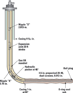
Screen and gravel selection. The screens needed to resist a 600°F steam-injection temperature and relatively high inflows5 of 52 ft/sec. Nodal analysis comparisons were made for nine scenarios, with open-hole sizes ranging from 3-7/8 in. to 8-1/2 in., various screen types and sizes, and gravel packed versus not gravel packed. Results of this analysis determined how the wells would be completed. The final modeled choice had a calculated production index of 2 bbl/psi/day and contained dual, prepacked screens with 4.5-in. OD and a 6- 1/8-in. open hole with gravel pack. Table 2 shows the screen characteristics.
Since no sand cores were available, the following equations were used to calculate the mean formation sand diameter (D50): Coberly6 µavg = D50formation/6.5 Blick and Civan7: µavg = [32*K/Ø]0.5 Combining these formulas yields D50formation = 6.5*[32*K/Ø]0.5 Saucier4 was used to calculate the mean gravel pack size: D50gravel = 5.5*D50formation Calculations indicated using 20 to 40 US mesh gravel with a 0.012-in. gauge screen opening.8 Ceramic proppant was selected as gravel for the prepacked screens and the open-hole gravel packs. This gravel is better at withstanding 600°F temperatures during steam injection. Sintered bauxitic materials have only 3.5% weight loss at 11 pH and 600°F.9 In comparison, Ottawa sand has a 46.1% weight loss at 11 pH and 540°F. Horizontal well drilling and fluids. An over-saturated, 10.5-ppg brine was used for drilling. The main components were viscosifier (polymer), pH control, filtrate control (starch), hole stabilizer, KCL and NaCL. The fluid contained bridging salt solids with a 3 to 174 µm range with D50 of 35 µm. The salt particles will create a filter cake on the formation face, trapping the polymer and starch molecules within the bridging agent. A packer was modified with 600°F seals and thoroughly bench tested.10 Meanwhile, drilling of the 1,000-ft, 6-1/8-in. horizontal section proceeded, followed by a wiper trip. Next, a Heviwater, 10.5-ppg brine pill was displaced 200 ft into the casing shoe. Then, dual, prepacked screens were run into the open hole with 2-3/8-in. washpipe11 and the thermal hydraulic packer. The screens were then spaced: a minimum of 5 ft from bottom and 15 to 20 ft inside the casing shoe. The brine pill was circulated to surface (<2 bbl/min.) with 10-ppg brine filtered to 5 µm. Clean fluid returns with less than 20 NTU are important.12 The greater part of the brine pill was circulated to surface, while remaining filter cake particles were produced through the screens. Also, during steam injection, the salt will dissolve and the polymer will break due to high temperature. The hydraulic packer was set at about a 45° inclination and the setting tool was released, Fig. 1.
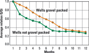
The ideal fluid for gravel packing is clean, under-saturated 9.5-ppg brine, filtered at 2 µm with less than 20 NTU. The main brine components used were KCL and NaCL and ranged from 8.5 to 10.5 ppg, largely for economic reasons. Gravel pack pumping design. The basic process for the horizontal gravel packing process is two-step.13 The slurry, brine and gravel was pumped at rates where gravel transport is achieved by the “alpha wave” propagating dune. This step will fill about 70% to 90% of the horizontal annulus.5 When this dune reaches the toe, a backward packing process, the “beta wave” is initiated and back-propagated toward the heel. A gravel-pack simulation was performed with Schlumberger’s SandCADE program. It recommended a 2.3 bbl/min pump rate and sand concentration of 0.5 to 0.7 ppa; these parameters were successfully applied. RESULTS At least 1,500-psi final screen-out pressure was reached with all 18 wells. A total of 15 wells were gravel packed with a pack efficiency greater than 100%. Only three wells did not reach that efficiency. A summary of the gravel pack operational results is shown in Table 3. Well LL-3696, was drilled with a 7-in. amplifier, in which 4-1/2-in. pre-packed screens with an OD of 5.38 in. were lowered. Bigger screens were needed to complete the well with five control lines inside the screens. The control lines measure the reservoir temperature and pressure. When the gravel pack was initiated, an early screen-out occurred and pack efficiency was reached at only 48%. Most probably the amplifier did not drill exactly to 7-in. of open hole. For economic reasons, only seven wells were gravel packed with ceramic proppant and 11 with Ottawa sand. First results showed that the initial production decline rate using ceramic gravel was 10%, while the initial decline for the Ottawa was 22%. Long-term performance has yet to be investigated. There were production increases when 8.5-ppg gravel-pack fluids were used. Initial production rose by 32% and overall production by 15%. This can be explained by the dissolving capacity of the under-saturated 8.5-ppg brine. It dissolves the salt solids of the mud-cake faster than 9 to 10-ppg brines. However, this could also result in high losses, jeopardizing completing the gravel pack. Such fluid losses (840 bbl) occurred in only one well using 8.5-ppg brine. On the heavy side of the 9.5-ppg ideal, one-third more gravel was required when a gravel pack fluid of 10 ppg was used, probably due to slight formation fracturing. Two of the modified thermal packers with high-temperature seals were successfully run. The packers were exposed to 8,000 t of steam injection per well during a three-week period. In other areas with steam injection, six more modified packers were run, and to date, four were successfully subjected to steam injection. PRODUCTION PERFORMANCE To compare production results of different wells, the actual production, Q, is divided by the initial production, Qi. Only wells producing longer than six months after steam injection were selected. Initial results showed that for six, gravel packed wells, average production increased by 135 bopd after eight months of production compared to nine nearby non-gravel packed horizontal wells. This is 18% higher than would typically be the case after one year in the non-packed wells. After 10 months, no further difference in production decline was observed, Fig. 2.
With the other 12 wells, six underwent steam injection and produced for less than six months. Two wells produced longer than six months, but had no nearby comparative wells. The remaining four wells had not yet received steam injection. LESSONS LEARNED The displacement rate of the Heviwater brine should be lower than 2 bbl/min to avoid packer-seal damage. A circulation float shoe was used in the first two horizontal gravel packs. Through the shoe, the Heviwater brine pill was displaced to surface by 10-ppg clean brine. However, in the displacing process, pressures up to 1,200 psi at 0.5-1 bbl/min were observed in both wells. The hydraulic packer sets at 1,600 psi. It was suspected that the float shoe might have been plugged when the screens were run in. For that reason, the float shoe was substituted by a bull-plug. The O-ring seal sub was moved upward and placed between screens at one screen from the bottom. In the subsequent wells, the Heviwater brine was displaced through the screen below the O-ring seal sub. No high pressures were observed. Other lessons learned include:
For further evaluation, a horizontal well was gravel packed in December 2001 with seven control lines: two contain optical fiber to help locate the steam injected producing interval. Gravel pack performance analysis is continuing.
|
|||||||||||||||||||||||||||||||||||||||||||||||||||||||||||||||||||||||||||||||||||||
- Coiled tubing drilling’s role in the energy transition (March 2024)
- Using data to create new completion efficiencies (February 2024)
- Digital tool kit enhances real-time decision-making to improve drilling efficiency and performance (February 2024)
- E&P outside the U.S. maintains a disciplined pace (February 2024)
- U.S. operators reduce activity as crude prices plunge (February 2024)
- Drilling advances (January 2024)

