Laser ID inspection of CRA tubing
(LaserStream) LaserStream, LP based in Humble, Texas, has successfully scanned over 2,000 joints of CRA tubing. LaserStream utilizes a BEMIS (Bore Erosion Measurement and Inspection System) specifically modified to OCTG applications. The joints consisted of 3 ½ in. Outer Diameter CRA tubing with coupled premium connections. The service was performed onsite, in the pipeyard, at an average pace of 50 joints per day.
Laser ID inspection consists of deploying the BEMIS through the tubing on a cable. The scanner head rotates at 250 rpm, collecting over 3,000 points of measurement every rotation. The measurements are accurate to 1,000ths of an inch.
With millions of high resolution data points, the results are phenomenal. The data was used to determine:
- Material loss due to pitting and/or mechanical wear.
- Characterization of features to deduce if they were caused by wireline, coil tubing, corrosion or a manufacturing flaw.
- Detailed analysis starting at the pin nose through the entire tube, to the D1 area of the box. An area where ultrasonic techniques cannot provide an adequate inspection.
- Exactly where to cut the tube for rethread, by measuring where damage patterns ended.
- Coupling movement in some cases due to the wear pattern being “clocked” in the D1.
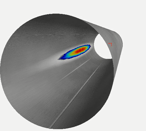
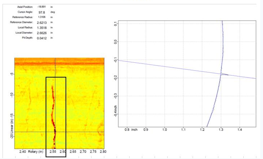
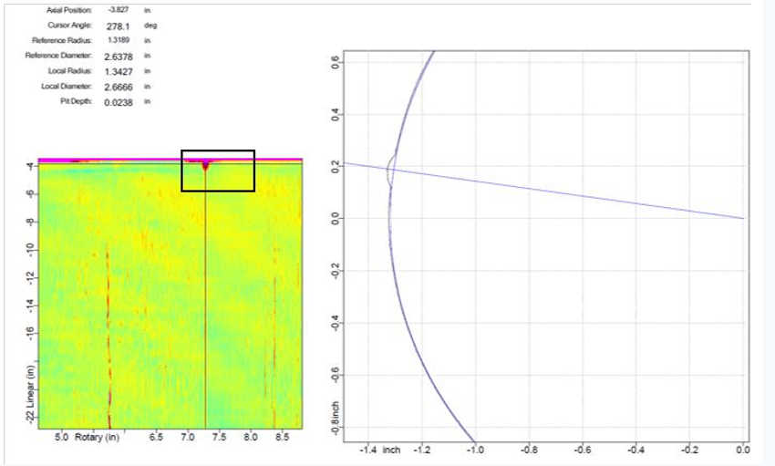
The images were analyzed with the LaserViewer software. The pipe ID is projected as a map with length (pipe length in inches) on the Y axis and radial position (360 degrees) on the X axis. The color pallet is adjusted to highlight various radii.Areas of material loss are then measured exactly in the cross section to the right. As the cursor is moved over the “pipe map,” the cross section adjusts accordingly.
A report summarizing the data was provided and used to determine trends.
The tube near the connections had a higher probability of damage. The tubing is stiffer there due to the coupling and the coupling is providing some standoff to the casing at that location.
The data can also be dumped into LaserViewer 3D or even solid works for FMEA analysis. This similar technique can be used on other tubulars such as drillpipe, vacuum insulated tubing, casing, and choke and kill lines. It can also be used in conjunction with other NDT methods to determine wall thickness at areas of interest.

