A practical approach to fluid integrity management in secondary recovery
Waterflooding continues to be an effective, economical option for secondary oil recovery in partially depleted reservoirs. Waterflood technologies have been applied successfully in a wide variety of oil fields worldwide, including both onshore and offshore operations. Significant resources are invested during the selection, design and implementation phases of secondary recovery operations to maximize return on investment (ROI).
However, after all the engineering, manpower and capital investments, the success of a waterflood system ultimately depends upon the geology of the producing formation, and the mobility ratio of the produced oil and injection water. For this reason, fluid integrity management is critical to the economic success of the secondary recovery effort throughout the life of the waterflood to maximize ROI. Both new and mature waterfloods can benefit greatly from a comprehensive effort to improve water quality. The dramatic effects of improved fluid integrity management were documented recently on a maturing waterflood in eastern Kansas.
BACKGROUND
The subject waterflood is located in Miami County, in east-central Kansas. Both the producing and water injection wells are conventional, vertical cased wells, set on an augmented 5-spot pattern. This shallow waterflood produces from the Peru, Squirrel and Hunt formations, which are siliceous limestone strata. Supply water is drawn from the Mississippi (Mississippi Lime) formation. The commingled injection flood water was being filtered through 100-micron filters prior to displacement into the formation.
The primary issues confronting this operator were excessive injection pressures in the flood water injection system, and rapid plugging of the cartridges in the water filtration unit at the water injection station. Water injection pressures were in excess of 900 psi and approaching the permitted pressure limits for this unit. The quantity of suspended solids in the injection water was exceeding the capacity of the water filtration unit, necessitating filter replacement every 24 to 48 hr. These issues were restricting the flood water injection rates to the point that the formation sweep capability was being impeded, and the effectiveness of the waterflood operation was degrading.
EVALUATION
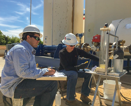
Identification of the suspended solids in the flood water injection system was the initial priority in this investigation. The utilization of membrane filtration test units has proven highly effective in evaluations such as this. These units permit the determination of the composition, quantity and particle size distribution of the suspended solids in water handling systems under dynamic conditions onsite, Fig. 1. Dynamic testing onsite is critical for the accurate identification of suspended solids in a flood water system. Pressure, temperature and velocity changes all impact the composition and quantity of suspended solids in an aqueous system. Augmentation of dissolved gas concentrations (carbon dioxide and hydrogen sulfide), and the potential introduction of dissolved oxygen into the flood water specimen during laboratory testing, are detrimental and counter-intuitive in accurate suspended solids analyses.
Suspended solids typically found in domestic United States waterflood operations consist of produced hydrocarbons, paraffins, asphaltenes, common oilfield mineral scales (calcite, gypsum, barite, celestite) iron carbonate, iron sulfide, sand, silt, clay, formation fines, bacterial sludges and other debris encountered in typical oil and gas operations. In the subject waterflood, suspended solids in the flood injection water were qualitatively and quantitatively identified as iron sulfide, calcite (calcium carbonate) and barite (barium sulfate) with trace quantities of formation fines. These suspended solids were heavily oil-wet with produced hydrocarbons.
The agglomeration of oil-wet solids in flood injection systems is a significant contributing factor in the reduction of waterflood efficiency. The downhole effect of these agglomerated solids in water injection wells is two-fold. The initial consequence is a reduction of permeability at the formation face and near-wellbore caused by the physical plugging of the formation pore throats by the oil-wet solids. The second consequence is a wettability reversal at the formation face and near-wellbore.
The vast majority of reservoir rocks are either water-wet or mixed-wet in their native state. This propagates an environment conducive to waterflood operations, due to a reduced hydraulic energy requirement for water displacement into the flood reservoir. As oil-wet solids amass at the formation face, a coating is created that results in a near-wellbore wettability reversal to an oil-wet state. This wettability reversal greatly increases the interfacial tension between the flood injection water and the formation face.
The combined two-fold effect of formation plugging and wettability reversal caused by agglomerated oil-wet solids greatly restricts the pumpability of flood water. This propagates not only reduced water injection rates and increased injection pressures, but also contributes greatly to the overall reduction in unit oil production efficiency. Maximum waterflood efficiency is only achieved when the quantity and velocity of the flood water is sufficient to increase the mobility of entrained reservoir oil.
REMEDIATION
The initial priority in the remediation of the subject waterflood was the restoration of the formation face and near-wellbore area of the water injection wells to a water-wet state through the removal of the accumulated oil-wet solids. The majority of the suspended solids in the injection water of this system were identified as heavily oil-wet acid solubles (iron sulfide, calcite). For this reason, downhole acid washing was determined to be a viable option for this downhole remediation.
When designing acid washing treatments, both mineral and organic acids should be considered for the remedial treatment. The quantity and type of solids to be removed, thermal limitations of some organic acids, system dynamics, and treatment economics should all be factored into the acid selection process. The ultimate objective of the remedial treatment is to remove agglomerated solids and return the near-wellbore area to its original condition, while minimizing tubular and formation damage. Acid selection and application are especially critical when dealing with acid-reactive zones, such as limestone and dolomite formations. Maintaining formation integrity in flood injection wells is critical to the long-term viability of a waterflood.
In addition to acid selection, additive packages should be selected and tailored carefully to the specific treatment requirements. Acid corrosion inhibitor is a critical component of all acid washing systems, to protect surface and downhole equipment. Since hydrocarbon films are impervious to the majority of mineral and organic acids, the incorporation of mutual solvents and/or surfactants is vital to the success of the acidizing treatment. These additives de-oil and water-wet solids to allow acid contact. The incorporation of non-emulsifiers into the acid package is also critical to mediate the potential for downhole acid-induced emulsions. The utilization of non-emulsifiers is especially important when acidizing producing wells and other systems, where copious amounts of hydrocarbons are present.
In acidizing treatments where the liberation of high concentrations of soluble iron is possible (such as the dissolving of iron sulfide), the incorporation of an iron control additive in the acid is crucial. This additive prevents the precipitation of ferric hydroxide from heavily iron-laden spent-acid solutions. Under specific anaerobic conditions, ferric hydroxide can revert to form iron magnetite. Both of these solids can precipitate and create problematic secondary downhole plugging.
The liberation of hydrogen sulfide (H2S) when iron sulfide is dissolved by acid is a critical issue that must be addressed in the design phase of an acid treatment. The primary concern is the safety of field personnel and protection from this poison gas. A secondary concern is the protection of downhole and surface equipment from sulfide stress cracking and hydrogen blistering/embrittlement. The incorporation of corrosion inhibitors and/or sulfide cracking agents is sometimes required in these applications.
Local acid pumping companies are experts in their field and a vital resource in designing specific acid packages to meet individual treatment needs. In addition to acid washing, matrix acidizing and acid fracturing are valuable tools that may be used, as needed, to maintain the long-term viability of a waterflood.
MAINTENANCE
Following restoration of the water injection wells in the subject waterflood, a program was implemented to improve injection water quality to maintain the integrity of this injection system. The use of a membrane flow cell can be extremely valuable in the design of a water treating program such as this. These field test units allow on-site evaluation of the effectiveness of various treating additives with fluids from the system in real time under dynamic conditions, Fig. 2. Typically, water treating products are complex formulations of surfactants, quaternary ammonium chlorides, ethoxylated amines and other chemistries designed to provide a synergistic performance in the water handling system. These products de-oil and water-wet suspended solids, disperse deposited solids and reduce the interfacial and surface tension in the aqueous phase of the system.
Concurrent to the restoration of the water injection wells in the subject water flood, additional work was implemented upstream in the producing wells, to assure the continued integrity of this system. Since an appreciable quantity of the injection water in this unit was connate water from the production system, management of water quality from this perspective was vital to the overall operational success of the water flood. The suspended solids previously identified in the injection water were oil-wet iron sulfide, calcium carbonate and barium sulfate, with trace quantities of formation fines. Identification of the source of these suspended solids in the production system was the next step in maintaining fluid integrity in this flood injection system.
While oil production is the primary purpose of waterflood operations, it is paramount to the success of the flood that oil concentrations are minimized in the water injection system. Oil in water carryover concentrations may be monitored easily at the water discharge legs of separation equipment in the production system and typically at the water injection system pumps. Acceptable oil-in-water carryover concentrations vary according to system efficiencies and reservoir dynamics, but ideally should be maintained below 100 ppm.
Common contributing factors to high oil-in-water carryover values in oil production systems are: 1) The incomplete resolution of water internal emulsions, due to improper demulsification; 2) The presence of invert, water external emulsions; 3) Stable or cut emulsions caused by production equipment malfunction or an incompatible production chemical treating program; 4) The presence of bacterial biomass; 5) Malfunctioning separation equipment, or equipment operated above the rated operational capacity; and 6) High concentrations of suspended solids in the water phase.
In properly functioning production separation equipment, an appreciable portion of the oil-in-water carryover often can be attributed to oil-wet suspended solids. Agglomerated oil “piggybacks” on the suspended solids present in the produced water. In these situations, oil carryover concentrations often can be reduced by lowering suspended solids concentrations in the produced water. For this approach to be effective, the suspended solids must be composed of mineral scales, bacterial sludges, etc., and not sand, silt, clay or other solids originating in the formation.
Another option in the reduction of oil in water carryover from oil-wet suspended solids would be the chemical injection of a water treating additive into the water discharge legs of the production separation equipment. This additive would de-oil and water-wet the suspended solids under the turbulent flow provided, as the produced water was transferred from the separation equipment to the water storage tank(s). Under the quiescence of the water storage facility, the oil would separate and could be skimmed from the top of the water tank, as necessary. This would further reduce the quantity of oil in the flood injection water.
A secondary concern with suspended solids in produced fluids is the potential deposition and accumulation of these solids in the production separation equipment. Most waterflood piping systems operate under turbulent, or at least transitional flow. The quiescence of separation equipment permits the deposition of solids into the bottom of the water phase of these vessels. This deposition can be significant in maturing waterfloods, where vessel cleaning and maintenance has not been a priority. These accumulated solids reduce the retention time and operational efficiency of the treating vessels, which can contribute to reduced fluid separation efficiency and increased oil in water carry-over.
Iron sulfide was a major component in the suspended solids found in the injection water of the subject waterflood. Iron sulfide (FeS) control in sour systems is critical for effective fluid integrity management in secondary recovery operations. While iron sulfide may be produced by the direct combining of iron and sulfur under extreme heat, in aqueous systems it is typically created from the reaction of dissolved soluble iron (Fe++) and hydrogen sulfide (H2S). Iron sulfide is a dark brown/black, water-insoluble solid with an affinity for hydrocarbons.
Iron sulfide mitigation may be achieved by managing the concentrations of the reaction components. Dissolved iron concentrations can be reduced in produced fluids with the implementation of a comprehensive downhole corrosion treating program in the producing wells. Downhole corrosion control also should be considered for water supply wells and all other source make-up waters utilized in the flood operation.
Dissolved hydrogen sulfide concentrations often can be reduced by managing sulfate reducing bacterial (SRB) activity, using biocide treatments. In severe situations, the dissolved hydrogen sulfide concentration may be managed with strategic injection of hydrogen sulfide scavengers. Systems containing profuse amounts of deposited or suspended iron sulfide also may be managed with the application of surfactants and/or acids.
The presence of dissolved oxygen in produced fluids is a serious issue in any oil and gas system. Dissolved oxygen causes cathodic depolarization in the electrochemical corrosion process that greatly accelerates the corrosion rate of steel. Secondary reactions of the liberated iron from the corrosion process also can contribute to significant increases in suspended solids concentrations, such as iron oxide and iron sulfide, in aqueous systems. In addition to direct chemical reactions, the presence of dissolved oxygen promotes the propagation of aerobic, slime-forming bacterial activity, and also acts as a catalyst in the formation of iron sulfide, Fig. 3.
Dissolved oxygen is never found in connate produced fluids. Its presence is always the result of surface operations that allow the entrance of atmospheric oxygen into the system. For this reason, best practices are critical in the prevention of fluid oxygenation. Mechanical repairs and operational changes should be the first line of defense in the deoxygenation of a system. Only after the exhaustion of all mechanical options should chemical oxygen scavenging be considered. This approach provides the greatest long-term ROI. Common sources of oxygen entry in mature or maturing waterfloods include:
- Leaking wellheads on producing wells and water supply wells
- Improperly vented annulus on producing wells and water supply wells
- Improperly maintained stuffing boxes, polish rods and production T’s on rod pump wells
- Improper venting of atmospheric fluid separation equipment
- Malfunctioning thief hatch seals or open/improperly closed thief hatches on water tanks
- Improper blanketing of water handling and storage tanks
- Cascading fluid in water tanks, resulting from missing/malfunctioning downcomers
- Leaking pump packing/seals on water transfer pumps
- Utilization of fresh/surface water in lease operations.
As previously stated, dissolved oxygen acts as a catalyst in the formation of iron sulfide in aqueous systems. For this reason, in sour systems such as the subject waterflood, prevention of fluid oxygenation is critical in the management of iron sulfide concentrations.
Control of mineral scale deposition is another significant factor in fluid integrity management. In the subject waterflood, both calcite (calcium carbonate) and barite (barium sulfate) were present in the analyzed suspended solids. Mineral scale formation can occur in brine systems when either the physical environment of the fluid is altered or the concentration of the mineral scale is increased, such as through fluid commingling, to the point that the solubility limits of the fluid are exceeded.
Calcite solubility is greatly influenced by the physical environment. Increasing temperature, lowering pressure and increasing fluid pH all significantly reduce calcite solubility and can induce calcite precipitation. Increasing the concentration of the mineral-forming ions, such as can occur with commingling of brines, can result in the formation of calcite in concentrations exceeding the solubility limits of the fluid, causing calcite precipitation.
The solubility of sulfate scales, such as gypsum, barite and celestite are much less affected by physical environment manipulations. Precipitation of these scales is typically initiated by fluid commingling which produces scale concentrations that exceed fluid solubility limits. Sulfate scale supersaturation is easily obtained, due to the limited water solubility of
these scales.
Control of both carbonate and sulfate scales can be achieved by a combination of best practices in commingling fluids and, when necessary, the implementation of a comprehensive chemical scale inhibition program.
OPTIMIZATION
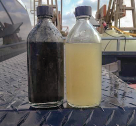
Following the remediation of the water injection wells and the implementation of a comprehensive upstream fluid integrity management program in the subject waterflood, system dynamics improved dramatically. Flood injection water quality was improved significantly, Fig. 4. As a direct result of this water quality improvement, and the remediation of the water injection wells, flood water injection pressures were lowered 48%. Flood water injection rate capabilities were increased 52%.
In addition, the improved water quality provided for the incorporation of smaller micron filters in the water injection system. Prior to treatment, 100-micron filters were being plugged every 24 to 48 hr. Following implementation of the remediation program, water quality improved to the point that 10-micron filters could be utilized and changed weekly. This unit responded very well to the increased fluid push, providing a 26% increase in the daily oil production.
While the dramatic improvements of the subject waterflood should not be considered typical, the data do illuminate the benefits of a practical systems approach to waterflood fluid integrity management. ![]()
REFERENCES
- Ostroff, A. G., Introduction to Oilfield Water Technology, National Association Of Corrosion Engineers, Houston, Texas, 1979.
- Patton, C. C., Applied Water Technology, Campbell Petroleum Series, Norman, Okla., 1995.
- Robertson, L. V., “Internal corrosion mechanisms,” Proceedings of University of Oklahoma Corrosion Control Course, June 1–3, 2016.
- Bradley, H. B., Petroleum Engineering Handbook, Society of Petroleum Engineers, Richardson, Texas, 1992.
- Moore, K. H., “Stop sucker rod failures to save money,” Petroleum Engineer International, July 1981, p. 24.
- NACE: TPC Publication 3, “Microbiologically influenced corrosion and biofouling in oilfield equipment,” NACE International, Houston, Texas, 1990.
- NACE Standard RP0475-91: Selection of Metallic Materials to be Used in All Phases of Water handling for Injection into Oil Bearing Formations, NACE International, Houston, Texas, 1991.
- Uhlig, H H., Corrosion and Corrosion Control, Second Edition, John Wiley & Sons, Inc., New York, NY, 1971.
- Fink, Johannes Karl, Oil Field Corrosion, Gulf Professional Publishing, Burlington, Mass., 2003.
- Eckenfelder, W. Wesley, Jr., Water Quality Engineering For Practicing Engineers, CBI Publishing Company, Boston, Mass., 1970.
- Van Poollen, H. K., Fundamentals of Enhanced Oil Recovery, PennWell Books, Tulsa, Okla., 1980.
- API: Treating Oil Field Emulsions, Third Edition, American Petroleum Institute, 1974.
- What's new in production (February 2024)
- Prices and governmental policies combine to stymie Canadian upstream growth (February 2024)
- U.S. operators reduce activity as crude prices plunge (February 2024)
- U.S. producing gas wells increase despite low prices (February 2024)
- U.S. drilling: More of the same expected (February 2024)
- U.S. oil and natural gas production hits record highs (February 2024)
- Applying ultra-deep LWD resistivity technology successfully in a SAGD operation (May 2019)
- Adoption of wireless intelligent completions advances (May 2019)
- Majors double down as takeaway crunch eases (April 2019)
- What’s new in well logging and formation evaluation (April 2019)
- Qualification of a 20,000-psi subsea BOP: A collaborative approach (February 2019)
- ConocoPhillips’ Greg Leveille sees rapid trajectory of technical advancement continuing (February 2019)

