Operational flexibility, contingency planning are vital in solving well control issues
The community of well control engineers and specialists consists of a small number of experienced professionals providing an essential service to the industry: resolution under unusual circumstances. Unlike the majority of other services provided throughout the drilling, workover, completions and production stages, well control responders are tasked with providing proven procedures to resolve the most dynamic issues oil and gas operations have to offer.
Finding solutions to dynamic problems is nothing unique to well control. When a drilling rig takes a small kick, many variables are subject to change including: 1) influx volume; 2) pump pressure; and 3) casing pressure. One element that differentiates the well control resolution process from other services, is the lack of known or accessible data. This lack of data can be present in the following: a) casing and tubing integrity is often compromised; b) potentially parted strings can complicate the process immensely; and c) blowout flowrates are commonly unknown, but can be estimated if the correct data is available. Of course, these examples of uncertainties and unknowns do not present themselves on every job, but more often than not, these are standard obstacles for well control events.
EMERGENCY RESPONSE
To better understand the process of creating procedures for a multi-faceted no-job-is-the-same-as-the-last-event, we must first explore the moments immediately following a well control event. After the well control service provider is contacted via an emergency phone number, several specialists are immediately dispatched, either by vehicle, charter or commercial plane. Along with personnel, essential rapid response equipment is loaded on a trailer and dispatched to the wellsite. Upon arrival, personnel can assess site logistics, the required operating plan, limitations associated with location layout and the specialized equipment that will be required to complete the job. Additionally, while personnel are traveling to the wellsite, we request as many pictures of the well and surrounding location as possible. One small detail could substantially change the available resolution options.
Contrary to popular belief, when specialists arrive at the wellsite, we do not go running in to save the well like a group of firefighters pulling up to a burning house. If traveling by plane, well control specialists usually will arrive before the equipment. Many jobs require safety deluge spray monitors to be stationed around the well before it is safe for personnel to approach the flowing wellhead. If the well is flowing and has H2S, extra time is required to properly fit safety equipment and “mask-up.” Once it is safe to approach the well, the specialist will examine the situation and begin to form a forward operating plan.
Commingling knowledge/expertise.The forward operating plan is a collaboration between the well control service provider, the well operator’s onsite supervisors and office personnel, as well as any other third party personnel, as required. After the well situation has been observed, a conference call with all pertinent leaders is held to discuss the plan moving forward. The strategy going forward attempts to consider all possible outcomes that could potentially result from each step in the process, to avoid being caught off guard by an unexpected outcome. Well control specialists strive to predict all potential outcomes but, in most cases, there is a need to continually adjust and update procedures. If A, B, and C were initially included in the forward operating plan as possible outcomes, and result D happens, the job is stopped and the plan is revised. Whether attempting to bring a flowing well back under control or planning a kick resolution, an essential key to success is to update and revise the operating plan.
Lack of data impedes process. A primary hurdle to such planning is the lack of known data. Many details of the plan cannot be determined until after a process has been initiated. The following example, involving a workover rig pulling tubing, highlights this process. After the BOPs were accidentally closed while pulling tubing, the tubing connection-upset tagged the closed ram, resulting in the BOPs being pulled off of the wellhead. As the rig crew waited to assess the situation, the well had been swabbed in, and began flowing at the surface from the tubing and the void where the separated BOPs had been disconnected from the wellhead. With a situation like this, it is difficult to determine the optimal rate to pump fluids down a casing outlet, with multiple flowing exit points of an unknown rate.
The following case study provides details about a recent well control event and outlines how the process of bringing a well back under control requires patience, contingency planning, and years of experience and knowledge.
CASE STUDY
A drilling rig was tripping out of the hole for a bit change when the operator took a large kick. A total of 1,520 ft of heavy weight drill pipe (HWDP) and BHA remained in the hole on an 18,429 ft TVD well. Although the BOPs were rated for 10,000 psi, the DSA and flow cross were rated for 5,000 psi. Additionally, this location did not have an open reserve pit, which could be used to flow the well to, in order to reduce the pressures induced on the BOP stack. Initially, the casing pressure gauge on the rig floor remote choke panel was not accurate and showed 600 psi, whereas the actual casing pressure read from the choke manifold was 4,100 psi. Cudd Well Control was contacted via the 24/7 emergency response telephone number and personnel were dispatched to the location immediately. As the closest well control first responder was arriving on location, the rest of the team was already en route by charter plane.
Initial inspection. Upon arrival, the well control specialist and company representatives inspected the well site and began initial discussions for well control operations. Cudd Well Control was informed the BHA consisted of a dart valve, 4-in. HWDP, jars, a motor and bit. Due to the potential of uncontrolled gas flow, because the pressures exceeded the equipment pressure rating, firefighting equipment was dispatched to the location. The initial forward operating plan included rigging up deluge equipment, clearing nonessential equipment from the location, and securing a path to pump down the 4-in. HWDP to kill the well. However, the company suspected that the current depth of the drillstring was not deep enough to create adequate hydrostatic pressure to kill the well.
By the time first responders arrived on location, the casing pressure had built up to 6,750 psi. A set of slip-type elevators (YT) were ordered to secure the HWDP to the rig floor and prevent the possibility of pipe being ejected. Once the casing pressure built to 7,400 psi, the choke was opened, allowing some gas to bleed off. The goal was to reduce the pressure, to prevent the 5,000 psi rated components from leaking. The current rig setup only allowed for liquid returns to bleed down to the mud system, which would have contaminated it, and limited the volume of fluid that could be handled after flowback. This, in effect, became a delicate balancing act, which lasted until additional flowback equipment could be installed. This resulted in the casing pressure falling to 7,000 psi. Once closed, the pressure would build, resulting in multiple choke openings to periodically bled back to 6,800 psi. During this time frame, the well control deluge equipment was rigged up, along with a frac tank spotted on the edge of the location.
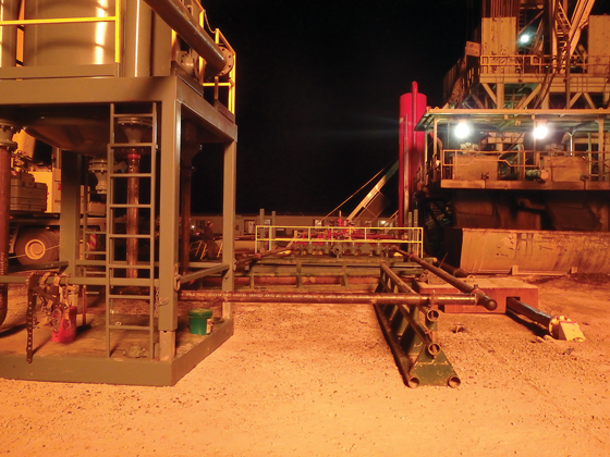
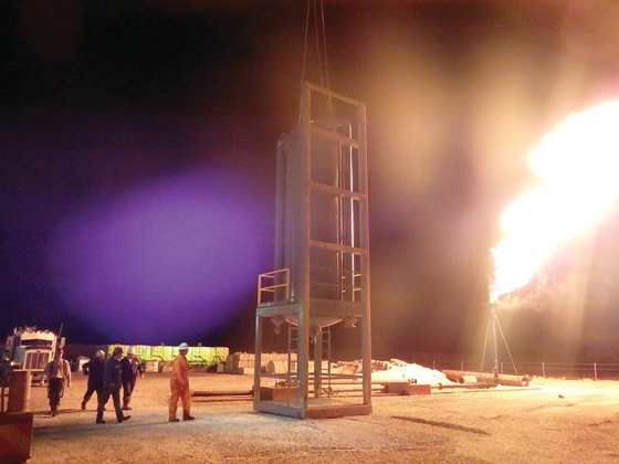
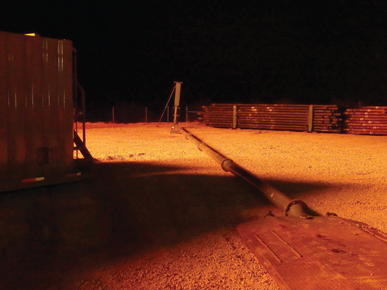
Nonessential equipment was then removed from the wellsite. A crane, choke manifold, high-capacity gas separator, and a flow and vent line were installed, Fig 1. The dual hydraulic choke manifold was installed in line with the panic line on the rig choke manifold and tied into the high-capacity gas separator, Fig. 2. Welders then fabricated custom bends and elbows in the flow and vent lines to accommodate the anticipated high volume of flow. The flow line was laid to the frac tanks and the vent line was run to the flare stack, Fig. 3. At this point, 5,000 psi pop-off valves were then installed on the rig pumps.
Early the next morning, the well was opened up to the newly installed choke manifold and gas separator. The casing pressure was allowed to fall to 4,600 psi. After the YT elevators arrived, a well control specialist attached them to the HWDP, securing them to the BOP stack. The casing pressure was bled down to 1,850 psi and appeared to stabilize. A top-drive was made up to the HWDP and 18.6 ppg mud was pumped down the string, starting at 0.5 bpm, raising slowly until eventually reaching 7.7 bpm. The mud was then swapped to 15.6 ppg after 65 bbl of 18.6 ppg mud had been pumped. The pump rate was lowered to 4 bpm to allow time for mud in the system to build up. After 114 bbl had been pumped, the casing pressure read 1,050 psi and the drill pipe pressure read 780 psi. After 200 bbl had been pumped, casing pressure built to 4,200 psi and drill pipe pressure increased to 2,280 psi. The pump was then shut down and casing pressure fell to 3,750 psi. A total of 207 bbl had been pumped before the 5,000 psi pop-off valve limit was reached.
After that, the choke was opened, allowing the casing pressure to fall to 3,100 psi. The choke was then closed, and the casing pressure built back to 3,600 psi. After the choke was once again opened, the casing pressure fell to 3,050 psi before mud was spotted flowing at the frac tank. The choke was shut again and 15.6 ppg mud was immediately pumped down the string. The pump pressure once again approached 5,000 psi, and the pop-off valves triggered. The casing pressure rose to 4,250 psi after 12.6 bbl had been pumped downhole. A total of 220 bbl had been pumped and the casing pressure stabilized at 3,960 psi.
Next, a safety meeting was held to discuss the revised forward operating plan to build up mud in the slugging pit to 19 ppg, and continue with a modified lubricate and bleed operation throughout the night. If no progress could be made, other options, such as utilizing a snubbing unit or coiled tubing, would be evaluated. The choke was opened to bleed pressure, while mud was pumped down the string. The modified lubricate and bleed operation consisted of pumping at a slow rate down the drillstring to 1,520 ft, while bleeding a gas equivalent to the added hydrostatic pressure at the surface from the casing. After the pump pressure rose to 5,000 psi with only 3 bbl pumped, the decision was made to shut-down the pump. The casing pressure began building to 4,500 psi.
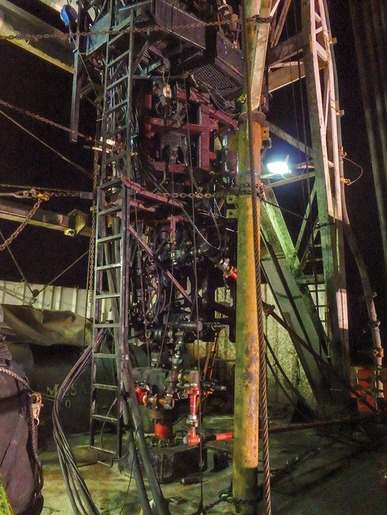
Modification of plan forward. The revised plan was to run in the hole to the 7-in. casing shoe with a snubbing unit, circulate the well from a greater depth, and kill the well. To create enough room for the snubbing unit on the rig floor, 143 stands of drill pipe, racked in the derrick, had to be laid down. A spacer spool and double BOP with pipe and slip rams were installed and were stripped over the HWDP after the rotary and rotary beam assembly were temporarily removed. The spool installation allowed for the bottom flange of the rig assisted snubbing unit to be at the rig floor height, Fig. 4. Once a 10-ft pup joint and XN nipple were made up to the HWDP, the snubbing unit was stripped over the string and nippled up to the assembly.
The choke was then opened, and the casing pressure fell from 4,880 psi to 1,560 psi. The snubbing crew then began snubbing the string in the hole while the well was allowed to bleed on the backside. Casing pressure fell to 250 psi before building back to 1,500 psi. By the time the crew was able to run to 10,075 ft, the casing pressure was 2,880 psi. The mud weight was raised to 16 ppg. After running pipe to the casing shoe at 15,834 ft, as planned, the pipe then appeared to be stuck. The decision was made to proceed with pumping and killing the well. The pump was brought up to 5.3 bpm and, after pumping 149.4 bbl, pump pressure increased sharply to 3,000 psi, indicating the bit may be plugged. More attempts were made to pump slowly, but the drill pipe pressure would not
bleed down.
Solution strategy updated again. Next, the drill pipe pressure above the dart valve was bled off and additional attempts were made to free the pipe by working the pipe up and down and jarring it loose. After discussions with company representatives, the forward operating plan was once again changed, to run inside the drillstring with wireline, perforate above the dart valve, and circulate at a higher depth with 17.8 ppg mud to kill the well.
A wireline unit was rigged up and ran the perforating gun to a depth of 14,326 ft, and successfully fired. Once the wireline was pulled out of the hole and rigged down, 17.8 ppg mud was then pumped down the drillstring. When the pump pressures began to increase, the pump was shut down. Discussions about swapping back to the rig mud system to track gains and losses were held. The casing pressure climbed to 1,330 psi. Rather than switching to the rig mud system, which would have limited the return handling capabilities during critical well control operations, returns continued to the frac tanks. However, this hampered the ability to accurately determine return volumes. After pumping 424 bbl, the drill pipe pressure was 515 psi and casing pressure was 750 psi.
After 462 bbl had been pumped, the drill pipe pressure was 1,120 psi and the casing pressure was 50 psi. A mud sample was collected and weighed 14.5 ppg. Pump pressure suddenly fell from 1,300 psi to 200 psi before building back to 1,200 psi, indicating a possible void had been filled. After 548 bbl had been pumped, the drill pipe pressure was 1,584 psi and the casing pressure was 0 psi. The returns were swapped to flow in the rig mud system instead of the frac tanks. After pumping 589 bbl, the drill pipe pressure was 1,827 psi and the casing pressure was 0 psi. The rise in the drill pipe pressure indicated that heavier mud may have begun to flow through the choke. A mud sample was collected and weighed 17.5+ ppg. At this point, 17.8 ppg mud continued to be circulated. After 1,021 bbl had been pumped, the drill pipe was picked up and was free. After 1,218 bbl had been pumped, the pump was shut down for a flow check, and the well was confirmed dead. The drillstring was hung off on the rig pipe rams, and the snubbing unit was rigged down.
AFTER ACTION REVIEW
The detailed job description provides insight into the ever-changing obstacles well control specialists and engineers are tasked with resolving. The key to continued, successful results, is the revision and execution of the forward operating plan. No specialist could have planned for the ever-changing situations encountered on the job.
The value delivered resulted from using past experience and on-site expertise to resolve each new issue as it arose. The Cudd Well Control team shifted direction and continued to work toward a successful, cost-effective solution. At the end of the day, this is the only thing “routine” about well control. ![]()
- Driving MPD adoption with performance-enhancing technologies (January 2024)
- Rig electrification drives down emissions, bolsters efficiency while improving onshore drilling economics (October 2023)
- Wellbore seal control and monitoring enhance deepwater MPD operations (October 2023)
- Advancing casing drilling to deepwater: Rethinking top hole well construction (August 2023)
- Mobile electric microgrids address power demands of high-intensity fracing (July 2023)
- Utilizing electronic data captured at the bit improves PDC design and drilling performance (July 2023)

