Latest advancements in drilling riser analysis technology
Despite the “lower for longer” oil price environment, many operators continue to explore for, and develop, oil and gas resources in some of the most challenging offshore environments around the world. Exploration and development drilling plans are ongoing in deepwater locations, such as West of Shetland; offshore eastern Canada; along Ireland’s Atlantic margin; in the South Atlantic Ocean; and offshore South Africa. All of these locations are characterized by the challenges of deep water, powerful ocean currents and high seas.

To cost-effectively drill in these locations requires careful planning of drilling operations to minimize non-productive time. A significant aspect of this planning involves analysis of the marine drilling riser system, to establish the limiting environmental (also known as metocean) conditions for particular riser operations, such as deploying and retrieving the riser and operating it in challenging conditions.
As the physical demands placed on the equipment have increased, so too has the level of accuracy available to model the riser system using specialized software tools. In this article, three recent technology developments that are enabling drilling to be undertaken in some of the world’s most challenging locations will be examined. These developments, which have been implemented into Wood Group’s DeepRiser global drilling riser analysis software, have enabled realistic modeling in drilling riser systems.
DRIFT-OFF IN DEEP WATER
Drilling operations in deep and ultra-deepwater depths are now nearly universally carried out, using dynamically positioned (DP) drilling vessels, as opposed to moored vessels. DP vessels maintain station over the well, using thrusters operated by a sophisticated control system. This system monitors the vessel position relative to the well, and uses the thrusters to counteract the environmental forces applied by wind, ocean currents and waves.
A key consideration when drilling from a DP vessel is what could happen if the system develops a fault, and the vessel is unable to maintain station. The fault types that can lead to this scenario include total loss of power, drive-off (when a control system fault causes the thrusters to push the vessel off-station) and failure of one or more individual thrusters. Of these scenarios, the most critical situation is usually a total loss of power—this can lead to a so-called drift-off event, where the vessel is pushed off-station by environmental forces.
If this situation occurs, it is necessary to disconnect the drilling riser from the well to prevent permanent damage to the drilling riser or the well, itself. The process for this is called the emergency disconnect sequence (EDS). During the EDS, the well is first sealed-in by the BOP, and the riser is then disconnected from the well at the lower marine riser package (LMRP). The timing of this sequence of events is crucial—the riser must be disconnected before any of the loads in the riser or the well system exceed the capacity of the equipment. Otherwise, permanent damage can result.
In practice, watch circles are used to ensure that the EDS is initiated in a timely manner. Watch circles are defined thresholds, in the form of horizontal distances from the well, which define when the EDS must be initiated. Usually, there are two watch circles—yellow and red. The red watch circle defines the last point at which the EDS must be started. If the vessel drifts past this point, and the EDS has not been initiated, then the riser will not have disconnected from the well before permanent damage occurs. The yellow watch circle defines the point at which preparations for the EDS should start.
Various approaches exist to calculate the locations of the watch circles. The simplest strategy is to define the watch circles as fixed percentages of the water depth. Although this approach was commonplace in the past, it suffers from a major drawback—it does not account for the metocean conditions. This is important because, for example, a vessel may drift-off much more quickly in a strong wind than in a strong current, and the speed of drift-off influences the position of the watch circles. Indeed, it has been shown that, in some circumstances, this approach could result in damage to the riser or well. For this reason, it has largely fallen out of favor with drilling contractors.
A more realistic approach is to perform a simulation of the vessel on its own, to predict its drift-off path under the action of the environmental forces acting on it. The forces generated are calculated as functions of the wind speed and direction, the ocean current speed and direction, and the sea state. These are applied in a dynamic simulation that calculates the trajectory of the vessel during drift-off. The calculated trajectory is then applied to a finite element (FE) global model of the riser system, in either a static or dynamic analysis. This is done to determine the point in the trajectory at which the riser must be disconnected to avoid damage (the so-called point of disconnect or POD), from which the red and yellow watch circles can be found. Although this “uncoupled” approach is still sometimes used today, it does not account for the effect that the riser, itself, has on the drift-off trajectory of the vessel. This can be significant, and omitting it often leads to results that are too conservative.
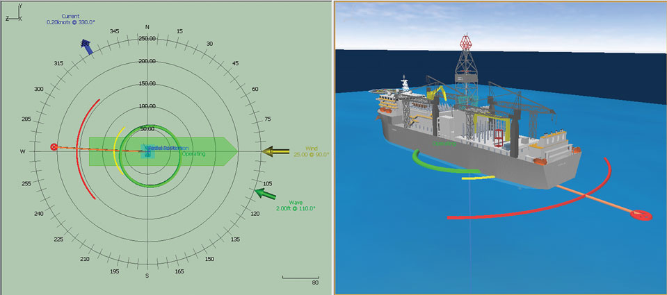
The latest approach for watch circle calculation, and the one employed by DeepRiser, is to use a fully-coupled scheme that includes both the vessel and the riser in a single, integrated model, Fig. 1. Dynamic analysis is performed, in which the environmental forces acting on the vessel (and riser) are calculated and applied at each step of the simulation. The result is a prediction of the vessel drift-off trajectory that accounts fully for the effect of the riser on the vessel drift-off, and calculates the location of the POD and the watch circles with the highest level of accuracy.
An advantage of the fully-coupled approach is that it avoids the potential for excessive conservatism that is a feature of uncoupled approaches. While drilling, an adequate minimum watch circle must be available to allow sufficient time for drilling operations to be suspended and for preparations to be made for the EDS, should the vessel undergo a drift-off event. In harsh environments, any excessive conservatism in the calculation of watch circles could result in suspending operations on the vessel unnecessarily and going on stand-by, which could have a significant impact on non-productive time and, consequently, drilling costs. Eliminating this conservatism can improve the economics of harsh-environment drilling substantially. For this reason, the fully-coupled approach is now becoming the industry standard.
EMERGENCY DISCONNECT EVENTS
There are many emergency scenarios, including the drift-off case just discussed, that can require the riser to be disconnected from the well. The physics of an emergency disconnect are quite complex. Many special factors must be considered when simulating this scenario.
The first consideration is the behavior of the riser tensioner system. This system applies the tension that gives the riser its ability to resist lateral loading, and the riser acts like a taught string. In an emergency disconnect scenario, the tensioner system has to be able to respond by lifting the riser enough to allow the LMRP to move clear of the BOP, while reducing the overall tension applied to the riser. All this must be achieved without damage to any of the riser equipment, including the telescopic joint, tension ring and the tensioning system.
The tensioner system uses a number of large hydraulic cylinders that are energized by an array of air pressure vessels (APVs) to develop the tension that is applied to the riser. A special valve, known as an anti-recoil valve (ARV), is situated on the hydraulic piping that connects the tensioner cylinders to the APVs, via a hydraulic accumulator. The purpose of the APV is to throttle the flow of hydraulic fluid to the tensioner cylinders in an accidental event, such as a riser parting or an emergency disconnect. Throttling the flow reduces the tension generated by the tensioner cylinder in a controlled way, and this helps to control the recoil of the riser following emergency disconnect.
In past drilling riser analyses, the tension applied by the riser tensioner was commonly modeled as a constant, vertical point-load at the top of the riser. However, such a simplistic approach is insufficient to model the behavior of the tensioner in an emergency disconnect.
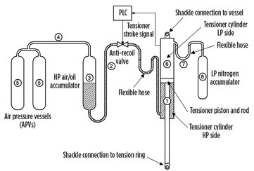
Instead, the new drilling riser analysis software incorporates a detailed hydro-pneumatic model that includes the individual hydraulic and pneumatic components of the tensioner system, Fig. 2. The components include hydraulic cylinders, ARV, accumulators, APVs and the piping between each of these components. Each individual tensioner cylinder can be modeled independently, and there can be any number from six to 16. This allows the program to simulate the three-dimensional response of the riser system to an emergency disconnect scenario. Facilities are provided to allow the user to replicate the logic of the programmable logic controller (PLC) that is used to control the throttling action of the ARV, including the control algorithms used by the most common types of riser tensioners today.
The second challenge associated with simulating an emergency disconnect event is modeling the behavior of the drilling mud within the riser, following disconnect. Drilling mud is used to provide pressure control within the well and to remove cuttings from the drill bit while drilling. The density of the drilling mud varies, but it is generally denser than seawater. For a number of reasons, the mud is rarely retained within the riser after disconnect—the bottom of the LMRP is open to the surrounding seawater and, because the mud is denser than seawater, it flows out of the bottom of the LMRP. This phenomenon has a significant effect on the behavior of the riser, as it causes a large downward drag load on the riser. Essentially, the mud attempts to pull the riser down with it, as the mud flows out of the riser.
To model this accurately, the software integrates a finite volume (FV) mud flow model with the FE structural model of the riser. The fluid flow model captures the complex physics of the column of mud within the drilling riser, as it collapses, following emergency disconnect, as well as the effect that this has on the riser’s response.
Being able to model this accurately is particularly important for deepwater, harsh-environment locations. The large water depths require the use of higher riser top tension that, when combined with vessel heave response in heavy seas, can reduce the range of metocean conditions, in which the riser can be safely disconnected, to very small levels. Accurate modeling of the response of the tensioner system and the drilling mud following disconnect is essential to verifying that the riser can be handled safely while maintaining an economically-viable operating envelope.
WELLHEAD AND CONDUCTOR MODELS
Recent developments within the offshore drilling industry have led to an increased focus on the fatigue of the wellhead, conductor and casing that can occur during drilling, workover, and plug-and-abandonment operations. These developments include the increased use of modern, sixth-generation mobile offshore drilling units that carry larger and heavier BOP stacks, which consequently place greater loads on the wellhead and well structure. Another challenge is the requirement to conduct a greater level of well intervention operations to maximize recovery from existing reservoirs.
The industry has strived to address these problems in a number of ways, and most notably via a series of JIPs that have aimed to develop a consistent methodology for wellhead fatigue analysis. In parallel with this effort, riser analysis software tools have been developed further to incorporate the latest modeling practices and analysis methodologies.

The updated software includes features that allow the wellhead, conductor, casing strings, intermediate cement and soil structure to be modeled with a degree of accuracy previously not available in a global riser analysis tool, Fig. 3. Through the use of pipe-in-pipe models, the software allows the individual strings that make up the well structure to be modeled explicitly. The pipe-in-pipe feature allows the bending stress distribution in the conductor, surface casing and any additional casing strings to be determined individually, including in situations where there is capacity for lateral motion, such as in the case of cement shortfall. This provides a higher level of accuracy than traditional “composite” models, where the properties of each of the strings in the well structure are combined into a single structure, with properties equivalent to the combined properties of the individual strings. The composite approach assumes that all strings deform together—something which is not the case where there is cement shortfall.
Additionally, the software provides a range of options to model the resistance to lateral motion provided by the soil surrounding the conductor. This support is modeled using load-deflection curves (known as P-y curves) that describe the resistance load provided by the soil as a function of the lateral deflection of the conductor. P-y curves are generated, based on a set of specific soil properties, such as undrained shear strength and submerged unit weight. Many standard models are included for soft clay, stiff clay and sand. Alternatively, the user can define their own P-y curves, where these have been calculated from the results of a geotechnical investigation.
The detailed wellhead, conductor and casing model bridges the gap between the older composite models previously used for global analysis, and the more intricate, three-dimensional local models typically developed for component analysis using FE analysis packages. While these don’t provide the same level of detail as the local component models, the detailed global models deliver improved fatigue-life predictions from global analyses at a fraction of the effort associated with developing local component models. The improved predictions are essential to demonstrating the feasibility of drilling, workover and plug-and-abandonment operations, especially in harsh- environment locations.
CONCLUSIONS
As the oil and gas industry adjusts to a new market reality, it remains clear that development of offshore reserves will continue to play an important role in meeting the world’s hydrocarbon energy demand. As easy-to-access resources are depleted, this will inevitably lead to further exploration in deepwater and harsh-environment locations. Ensuring that this can be done in an economically-sustainable way demands the use of new digital technologies that can simulate drilling operations with the highest-possible level of accuracy. Wood Group’s DeepRiser tool is an example of one such technology that is helping to maximize the viability of drilling operations in some of the world’s most challenging environments. ![]()
- Applying ultra-deep LWD resistivity technology successfully in a SAGD operation (May 2019)
- Adoption of wireless intelligent completions advances (May 2019)
- Majors double down as takeaway crunch eases (April 2019)
- What’s new in well logging and formation evaluation (April 2019)
- Qualification of a 20,000-psi subsea BOP: A collaborative approach (February 2019)
- ConocoPhillips’ Greg Leveille sees rapid trajectory of technical advancement continuing (February 2019)

