Subsea efficiency in harsh environments
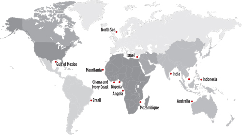
As much of the accessible offshore hydrocarbons have been discovered and produced, the search for new prospects has driven the industry to explore in more challenging deepwater locations across the globe, Fig 1. The growth trend in subsea deepwater (500 m to 1,499 m) and ultra-deepwater (1,500 m) drilling is expected to continue, as the oil and gas industry explores for new hydrocarbon sources.
SUBSEA SAFETY
As offshore operations continued to evolve, it became apparent that new subsea systems would be necessary to ensure safety and protect the environment. To help provide the equipment and expertise required by industry and regulatory agencies, EXPRO introduced innovative subsea technologies designed specifically to safely manage the containment of hydrocarbons between the seafloor and the drilling rig.
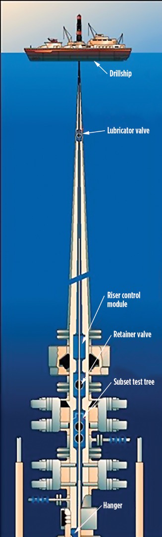
The systems can be deployed in the exploration and appraisal phase, during completion/intervention operations, or in abandonment activities. Safety systems form part of the landing string, which is deployed inside the marine riser and spaced out into the subsea BOP, Fig. 2. The landing string comprises a series of vertically stacked, high-reliability ball valves, and associated controls and monitoring systems.
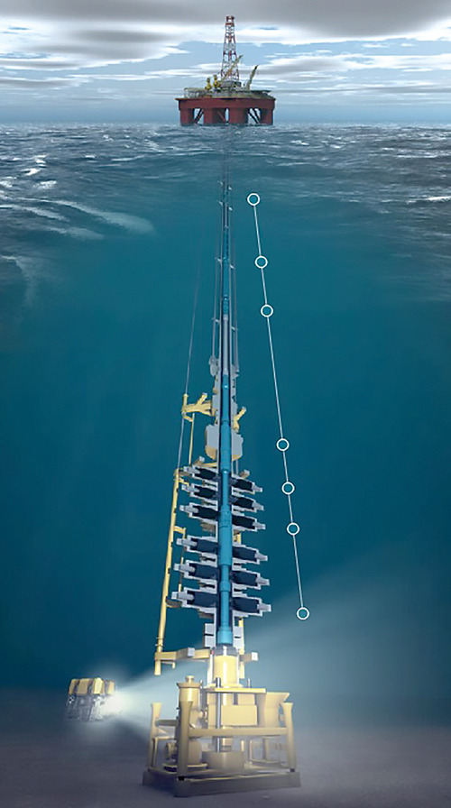
Unpredictable marine environment. During operations, it is imperative that the mobile offshore drilling unit (MODU) remains over the subsea wellhead. Floating MODUs are either moored, or dynamically positioned, to keep them in place, Fig. 3. These dynamic drilling units, particularly semisubmersibles and drillships, are designed to manage pitch, roll, yaw, heave, sway and surge as dynamic components, to keep the rig stationed directly over the wellhead.
One of the key risks for operations under live well conditions from a floating rig is the loss of vessel positioning. This drift can be caused by extreme sea conditions, hurricanes, failure of the dynamic positioning system, loss of anchor or engine power failure. In any case, a safety system is designed to isolate the well at the seafloor and safely contain hydrocarbons within the marine riser. This mitigates the risk to the rig and/or the surrounding marine environment, due to an unplanned hydrocarbon release in the event of a vessel drive-off or loss-of-station scenario.
Depending on the severity of the emergency, the well may be shut-in and monitored. Should the situation deteriorate further, the safety system can be unlatched, leaving the lower landing string ball valves closed and sealed on the well, while the rig moves off location. These safety systems are designed to fail-safe close (close on their own spring force) on shear ram activation in a catastrophic scenario, when there is limited time to perform a controlled shut-in and disconnect.
Containing operational crisis. When facing emergency situations during drilling operations, well control is achieved by closing the BOP rams to shut in the well. The marine riser is disconnected from the wellhead, utilizing a lower marine riser package (LMRP), before moving the rig to a safe position, Fig 4. When there is no time to react, the drillstring deployed within the marine riser is cut, using the BOP shear rams, and hung off above the LMRP. After the situation has been controlled, the severed drill pipe is fished and recovered back to the surface, and the damaged sections are replaced. The string is re-run before resuming operations. Re-entry on a well, post-pipe shearing, may require well kill operations prior to fishing and recompletion, and, in some cases, may result in the loss of the well.
COMPOUNDING ISSUES
Efficient subsea safety systems are designed to isolate the well in a controlled manner, while providing the mechanism for disconnect/unlatch and reconnect/relatch during exploration, completion and intervention operations. By utilizing a landing string system, NPT is reduced significantly during a shutdown or disconnect and drive-off scenario, by providing a controlled isolation of the wellbore and associated hydrocarbons. The LSS facilitates critical hydraulic and electrical feed-through to subsurface completion components. This translates into a potential savings of more than 24 hr of rig time in shallow waters, and up to 48 hr in deep water.
Formation challenges. System reliability is critical to achieve increased efficiencies in subsea operations. Harsh reservoir conditions often compound already challenging marine environments, such as HPHT, solids, wax, hydrates and increases in hydrostatic riser pressure. These situations create additional challenges designing and operating subsea equipment. A system failure under these conditions could result in NPT.
The potential consequences of a failure is proportional to water depth. This is due to the rig time associated with the retrieval and redeployment of subsea equipment, using a higher-specification MODU with incremental day rates. In addition to functional reliability (to safely contain hydrocarbons), operational reliability in successful deployment of the system is equally critical.
Meteorological disturbances/subsea currents. Deepwater, itself, is not a direct indicator of the harshness of the environment. For example, the North Sea is shallow, compared to the GOM. However, frequent winter storms, and the periodicity of waves, create a detrimental dynamic condition that can lead to the loss of rig position.
Even in a calm sea, strong subsurface currents can surge in counteracting directions at different layers within the water column, loading the marine riser and affecting the MODU’s ability to keep centered over the wellhead.
Subsea safety systems are, therefore, required to operate efficiently in all environments.
SYSTEM ACCOUNTABILITIES
The essential functions for landing string equipment are to: 1) establish provision for controlled and emergency well isolation; 2) contain riser inventory; 3) disconnect safely upon demand; 4) meet the prevailing legislative criteria on emergency shutdown and emergency quick-disconnect. To address different applications, landing string configurations should be flexible. For example, small-bore landing string systems are designed for E&A applications, or large-bore landing string systems can be used for development and intervention. EXPRO’s large-bore systems are classified further into mono-bore and dual-bore systems, designed to be used in conjunction with horizontal and vertical Christmas tree configurations, respectively. A typical landing string system (Fig. 5) consists of the following components:

Lubricator valve. The valve establishes a single or dual “fail-as-is” barrier at a pre-determined position (high or deepset) within the riser. The valve can maintain pressure control, while providing additional capacity for longer toolstrings prior to deployment in the well. Some operators classify the closed valve as a drop catcher device, which is a mechanical barrier for dropped objects, when deploying heavy intervention tooling.
Retainer valve. The valve minimizes the time taken to effect an emergency disconnect of the rig from the well, by performing the following sequential operations: 1) containing the riser inventory by means of a “fail-as-is” operable barrier; 2) displacing the trapped inventory between the retainer valve and primary barrier; and 3) allowing the activation of the disconnect package. The configuration is equipped with a tubular shear sub designed to contain pressure, can accommodate externally applied tensile and axial loads, and, most importantly, can be sheared by the BOP rams in the event that all other redundancies have failed.
Subsea test tree. The tree is the principle well control device and, as such, many of its functions are safety-critical. It provides a dual, independent, fail-safe closed barrier, which facilitates well control in the event of a controlled or emergency disconnection, without requiring the BOP to shear off.
Tubing hanger running tool. The latch section of a subsea test tree enables safe disconnection of the landing string within the BOP. The system facilitates the deployment and retrieval of the tubing hanger, using a hydraulically controlled lock piston.
LANDING STRING CONTROLS
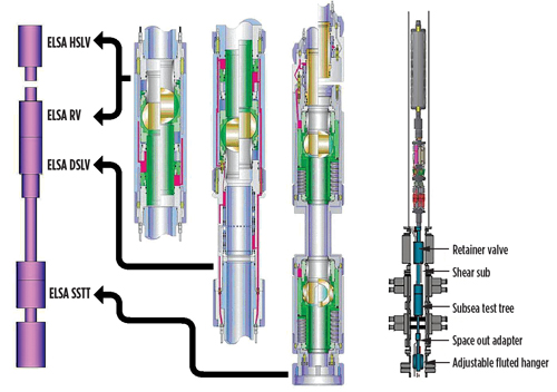
The conventional system for controlling landing strings in shallow waters is typically a direct hydraulic (DH) system. However, DH systems have time constraints and, in extreme conditions, the use of electro-hydraulic (EH) systems provides the required response, functional flexibility and communication for high-speed control, Fig. 6.
These controls also enable real-time data feedback, reduce the physical umbilical size on deepwater applications, and address the disconnect philosophy from dynamically positioned, mobile drilling units. The current system exceeds industry requirements for disconnect protocol, achieving system shut-in or well closure and disconnect, within 15 sec. It provides a fully integrated control system and, when applicable, it incorporates the operation of the tubing hanger running tool and tubing hanger functions. In addition, the landing string may be equipped with ancillary components that may include:
- Downhole monitoring gauge
- Intelligent well electro-hydraulic feed-throughs
- Subsurface safety valve actuation
- Gas injection for well unloading
- Chemical injection for wax or hydrate inhibition.
RELIABILITY ANALYSIS/TESTING
As the industry and regulatory agencies (BSEE) continue to raise safety standards in subsea development, experts have determined that system reliability is a key factor in reducing catastrophic incidents. Accordingly, API and the International Organization for Standardization (ISO) have developed industry standards for the design and qualification of subsea equipment. These rigorous standards incorporate requirements for certification, testing, reporting and third-party verification.
Operators and service providers have collaborated to develop technology to meet the new safety qualifications. This includes using sophisticated criticality analysis, to accurately chart the probability of failure modes and plot them against the severity of their consequences (FMECA). The results enable engineers to direct remedial efforts to areas that will produce the greatest value. Safety integrity level analysis also is being used to measure the performance required to produce a targeted level of risk reduction. This analysis is coupled with extensive workshop simulation tests to develop new safety systems.
The company recently developed a 6.045-in. slimline lubricator valve and subjected the system to qualification testing that closely simulates HPHT operating conditions at the point of deployment. The latest 15,000-psig subsea system is expected to meet API-6A-14A integrity standards for the design and manufacturing processes.
CASE STUDY 1
EXPRO recently partnered with a major producer in a Gulf of Mexico (GOM) operation and provided a 15,000-psig-rated, subsea landing string system and well test package, to deploy upper completions in a field at a water depth of 2,400 m. Environmental restrictions prohibit the amount of well tests that can be performed in the GOM. With a zero flaring restriction, hydrocarbons would be transferred to tender-assist tankers during the test. This specific operator had not performed such an operation in over 15 years, and required a service company to manage the well test design and operations.
Of particular importance was collecting data on the performance of chemical treatments for emulsion breaking and anti-foam treatments on live hydrocarbons at separator conditions, to optimize chemical treatment at the host facility post-commissioning of the new wells. This involved comingled flow from reservoirs with different properties, and resulted in an extended test period, beyond normal clean-up operations.
It also was recognized that the test duration would prohibit routine BOP testing. In most cases, BOP testing is carried out with a dedicated test tool, run on drill pipe, which requires recovery of the landing string to surface, an operation that usually takes 36 hr to 48 hr of rig time. The solution was to test the BOP stack with the landing string in-situ. The solution included a design review by engineering teams, to evaluate the impact of full annular pressure applied below the rams, after closing them against the components of the subsea test tree.
Due to the high pressures involved, the secondary emergency system was upgraded. This required the design and testing of 16,000-psi-rated burst discs. High-pressure, wire-reinforced, collapse-resistant control lines also were installed, to ensure that controls were maintained during the operations. The operational procedure was amended, and precautionary methods were outlined, to maintain positive supply pressure on control line functions, to guard against collapse from external pressure. This action was particularly important to prevent inadvertent actuation of critical functions, such as shut-down and disconnect.
During the client campaign, all operations were performed with zero NPT, allowing the operator to eliminate the dedicated test tool run, thereby saving a minimum of 36 hr of rig time. Further savings were realized, because there was no need to mobilize the stand-alone test string to the rig.
CASE STUDY 2
In a recent GOM project, EXPRO developed and qualified a lubricator valve (LV) to 15,000 psig and 350°F. In this application, the LV can be run at different positions in a landing string, either deep-set (closer to the BOP) or high-set (100 ft below the rotary table). A deepwater application typically requires a high-set LV; however, this would require the control umbilical for the lower section of the landing string to be run alongside the LV body.
Designing a slim valve. The challenge was to design an LV with an OD small enough to allow a 78-mm electro-hydraulic control umbilical to be run past the valve, prior to commencement of the first well operation. This led to the development of a 6.045-in., OD, slimline lubricator valve, which, when run within a 19.5-in., ID, marine riser, allows both the valve and a 78-mm umbilical to pass through without issues. If this development was not successful, it would require the client having to utilize a surface flow tree master valve to pressure test the surface equipment, which is not optimal for deepwater operations.
The delivery schedule for the newly designed LV was short. Design, manufacture, build and qualification had to be completed in a year. At the time (2014), the average material delivery ranged between 35 and 45 weeks for major machined components. The extended lead time meant that the project delivery team had just 10 weeks to successfully complete all workshop-build and qualification activities.
The design of the new slimline LV was based on an existing 15,000-psig-rated, larger-diameter LV. The reduction of the OD was achieved by designing the main housing with thinner wall thickness, and by modifying the internal components to interface with the modified main housing. A qualification program was required to confirm that the modified valve mechanism had not affected its capability of operating to the required design criteria.
Testing HPHT capabilities. The qualification of the assembly was performed at a dedicated facility in Aberdeen, UK, with custom test bays for gas, endurance and temperature tests. The gas test configuration was devised to enable the valve to be submerged completely in water underground, and for the application of pressures to enable a consistent testing approach. The methodology adopted in qualifying a 15,000-psig system can be split into three areas:
- Factory acceptance testing (FAT)
- Qualification and performance testing (QPT)
- System integration testing (SIT).
Factory acceptance testing (FAT). FAT is functional analysis, to ensure that the design is fit for operational purpose, prior to qualification and performance testing. This includes a 150% working pressure body test, followed by component level dimensional inspection to ensure the integrity of the assembly under the maximum pressure exposure. The QPT requirements are further divided into three main areas: 1) gas; 2) endurance; and 3) thermal testing.
- Gas testing. The LV has proven it is capable of providing a barrier over the full extent of test conditions, with nitrogen as a test medium. Seat test holds have been carried out successfully, within the allowable pressure losses for full working
pressure of 15,000 psig and low pressure of 300 psig gas. The assembly was stripped, visually inspected and QC-checked following the Product Specification Level (PSL) 3G gas testing. There were no signs of wear or damage, and all parts were accepted for rebuilding and continuation of the qualification program. - Endurance testing. Over the course of the temperature and endurance test program, the LV was functioned approximately 150 times. This number of operations was chosen according to the company’s maintenance standards. With usage during completions of 30 cycles per LV, these standards allow for four completions between maintenance programs. A test program of 150 cycles allows for a further 25% safety margin above the minimum safety standard.
- Temperature testing. The verification of the LV for cycling during extremes in operating temperature was accomplished with no reduction in the maximum working pressure rating of 15,000 psig. Of the 150 cycles performed on the LV, over 20 were at the maximum operating temperature of 121°C, while over 50 cycles were performed with the valvebore pressure held at 15,000 psig. This extended cyclic testing proved that the internal components of the newly designed valve would not degrade in operations.
System integration testing (SIT). On completion of the qualification test program, the lubricator valve was shipped to EXPRO’s Broussard, La., facility for SIT. The test program combined the surface control equipment, the upper and lower landing string assemblies, and third-party tools, to verify that the system met the operational requirements dictated by the client.
Successful completion of the SIT proved that the new design was technically viable, and allowed the client to run a lubricator valve instead of an SFT master valve during first completions, adding versatility, reliability and efficiency to the operations.
CONCLUSIONS
As the search for hydrocarbons moves into ever-greater water depths in new locations, the offshore industry will be required to solve new problems and overcome increasingly difficult operational issues. The impact of the marine environment, combined with demanding reservoir conditions, will challenge conventional wisdom and today’s equipment/procedures. As rig day rates remain a significant component in exploration and development costs, safety systems’ reliability will be paramount when deploying in deep water.
To address these issues, new industry standards are being developed to ensure that safety-critical subsea equipment is developed. When released, the API 17G standards will drive design enhancements to emerging well intervention tools that will increase quality and system reliability. The revised industry standards will provide confidence going forward that the next generation of systems will perform successfully in future applications. Finally, further operator and service company collaboration will be required to build new solutions, as frontiers are extended. ![]()
REFERENCES
- Infield, “Global perspectives: Deep & ultra-deepwater technology & projects report,” December 2008.
- More, D. J., “Advances in landing string technology for completion and intervention operations in deep water,” Offshore Technology Conference, 2003.
- Beitler, B., “New thinking required to improve safety,” www.offshore-mag.com, 2010.
- Coiled tubing drilling’s role in the energy transition (March 2024)
- Advancing offshore decarbonization through electrification of FPSOs (March 2024)
- Subsea technology- Corrosion monitoring: From failure to success (February 2024)
- Using data to create new completion efficiencies (February 2024)
- Digital tool kit enhances real-time decision-making to improve drilling efficiency and performance (February 2024)
- E&P outside the U.S. maintains a disciplined pace (February 2024)
- Applying ultra-deep LWD resistivity technology successfully in a SAGD operation (May 2019)
- Adoption of wireless intelligent completions advances (May 2019)
- Majors double down as takeaway crunch eases (April 2019)
- What’s new in well logging and formation evaluation (April 2019)
- Qualification of a 20,000-psi subsea BOP: A collaborative approach (February 2019)
- ConocoPhillips’ Greg Leveille sees rapid trajectory of technical advancement continuing (February 2019)

