Marginal wells re-drilled economically using directional CT and underbalanced conditions
The flood of crude oil that has overwhelmed worldwide markets has forced operators to re-evaluate the economic viability of their producing properties and leasehold inventory. Although oil in the ground generates no revenue, the act of drilling and producing reservoirs profitably in a sub-$40/bbl market is one of the most significant challenges that the industry has faced in many years.
To succeed in today’s economic environment, we must once again reinvent the way that we drill and produce hydrocarbons. To start, we should focus on finding new applications for under-utilized equipment and existing techniques, to access known reserves and minimize operational costs. Although painful, this downturn offers an opportunity for innovators to reduce costs through intellectual pursuits, rather than ramping-up R&D spending and new tool development.
COILED TUBING DRILLING
Since its first commercial deployment in 1976, coiled tubing drilling (CTD) has been applied in specific worldwide applications, resulting in savings of up to 30% to 40% compared to conventional drilling operations. This has been accomplished by:
- Reducing rig-time through quicker deployment and higher ROP.
- Increasing speed of mobilization in multi-well operations in close proximity.
- Reducing preparation requirements, having a smaller footprint, and using existing roads.
UNDERBALANCED DRILLING
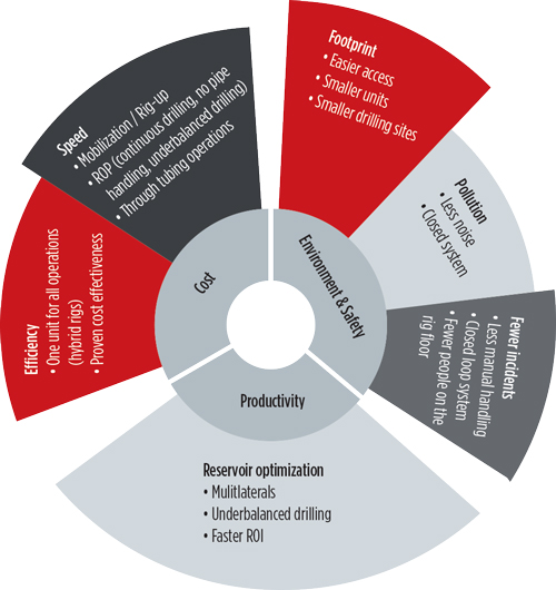
The benefits of underbalanced drilling (wellbore pressure less than formation pressure) can be fully exploited when used in a CT operation. With no joints to make up, CTD facilitates continuous drilling and pumping, allowing pressures to be maintained easily while ensuring underbalanced conditions 100% of the time. In some drilling operations, maintaining an underbalanced condition (UBD) is vital to protect the formation and/or maintain wellbore integrity. It also can enable the well to continue to produce while drilling and can, in some cases, increase ROP. When used in combination, CTD/UBD have untapped potential to reduce drilling costs and environmental impact while increasing ROP for a faster return-on-investment, Fig. 1.
MODERN DCTD SYSTEM
The development of a directional coiled tubing drilling (DCTD) system started in the 1990s and was first deployed in a horizontal application in West Texas, in 1991. The modern-day DCTD unit uses an armor-wrapped, flexible-string drilling system that is capable of accepting off-the-shelf motors and drill bits. It has been used extensively in well-established niche applications in Alaska, Saudi Arabia, Russia and parts of the U.S.
The awareness of the advantages that DCTD offers is increasing among operators. The most significant benefit is the ability to effectively, and safely, drill in an underbalanced condition, which enables the well to produce hydrocarbons during drilling. This allows real-time evaluation of reservoir productivity and protects the formation from damage. This can lead to significant improvements in productivity compared to wells drilled in an overbalanced environment. The DCTD application envelope is expanding, with tools up to 8½-in. OD being deployed worldwide to drill new wells and re-enter existing boreholes, to add multi-laterals and extend horizontal reach.
U.S. CASE STUDY
In November 2015, AnTech was selected by an independent operator to execute a DCTD operation in the Appalachian basin of the northeastern U.S. An updated geological model revealed the presence of conventional oil reserves within a few hundred feet of a previously drilled dry hole. Evaluation of a project, using CT to directionally drill a slim-hole sidetrack from the dry hole, indicated the reservoir could be accessed and produced at a profit.
In-depth engineering and commercial studies were performed before the job on the entire lease. The objective was to select a well that was technically feasible to re-enter and would provide the greatest return-on-investment. The financial analysis considered the well’s production potential, its likely decline curve, and the costs of drilling an intervention well using the current oil price. The financial modeling provided the operator with an accurate payback period. This analysis was then performed on four candidate wells, and showed that one specific well would provide the operator with the highest revenue flow in the shortest period of time.
OPERATIONAL PLAN
After confirming the commercial viability of the project, an engineering analysis was performed to structure an operational plan. The study indicated the best course of action would be to cement the wellbore back to KOP prior to running 4½-in. casing. A BHA would then exit the wellbore by kicking-off from the cement plug. After wellbore exit, the operator would drill a build-section to land in the reservoir, then geo-steer the borehole trajectory within a thin reservoir section.
The reservoir is susceptible to drilling fluid invasion damage, so it was decided that the entire formation would be drilled in an underbalanced condition. A mud system was designed that permitted carefully controlled amounts of nitrogen to be injected into the drilling fluid without suspending drilling.
BHA TECHNOLOGY
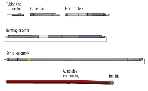
To withstand the harsh conditions associated with UBD, a new-type COLT BHA was selected for the project, Fig. 2. The BHA features real-time MWD/GR readings, a steerable motor and a continuously rotatable electric orientor, which enables precise wellbore placement. Real-time parameters delivered, include weight/torque-on-bit and vibration data, to ensure that the bit spends the maximum amount of time usefully engaged with the formation and to minimize mechanical specific energy used to drill the hole. This high volume of real-time data allows novel statistical techniques to be applied, resulting in increased confidence in survey data and derived positional measurements. To complete the BHA, a 27/8-in. downhole motor, with a maximum DLS of 50°/100 ft, and a 3¾-in. PDC bit were selected.
WELL PLAN
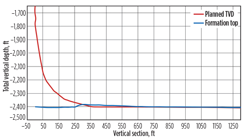
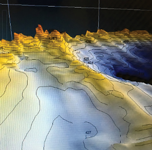
A well path (Fig. 3) was planned that tracked approximately 15 ft below the top of the reservoir, Fig. 4. The planned trajectory would be deep enough to ensure good contact with the producing formation, but not low enough to engage the oil-water contact believed to be 30 ft below the top of the reservoir. Because of the tight constraints, accurate depth control would be critical. To efficiently achieve the planned well path, the maximum DLS was set at 16°/100 ft, which is within the capabilities of the selected BHA.
MECHANICAL/HYDRAULICS MODELING
A pre-job analysis was performed using the company’s ATLAS modeling software to ascertain tubing forces and to optimize hydraulics. The study showed that sufficient WOB could be transferred to the bit at all depths to maintain an effective ROP. It showed that 2 3/8-in. OD CT would suffice, thus decreasing the weight onsite and easing the mobilization of materials to the wellsite.
The hydraulic models revealed that formation water could be used but would result in an overbalanced condition. Capturing the advantages of UBD would require the operator to strategically inject cryogenic nitrogen while drilling the reservoir. The analysis accounted for wellbore size/trajectory and the casing plan, as well as formation pressure and the desired underbalanced conditions.
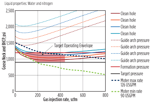
Figure 5 shows the predicted bottom hole circulating pressure (solid, curved lines) for a range of pump pressures and nitrogen injection rates. A thick line indicates sufficient hole cleaning; insufficient hole cleaning is depicted by a thin line. It is clear that the hole would be sufficiently cleaned at all expected flowrates. The flowrate limits for the 2 7/8-in. motor are also plotted. The software output shows the CT guide arch pressures generated at different flowrates (dashed lines). Minimizing guide arch pressure is an important consideration in maximizing CT fatigue life.
The choice of a fluid handling system was led by the operator’s considerable experience in the locality. The reservoir had historically produced low levels of natural gas, so fluid separation would be achieved with gravity tanks and a gas buster, to separate out the entrained nitrogen. Any oil that was produced would be skimmed from the top of a three-stage tank.
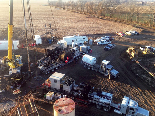
RIGGING-UP BHA/SERVICE EQUIPMENT
Once the well had been prepared for sidetracking, the service providers arrived on-site and began rigging up the directional CT unit and associated equipment, Fig. 6. The BHA was run on approximately 10,000 ft of 23/8-in. CT with a seven-conductor electric wireline injected. Using a crane, the injector and lubricators were suspended above the BOP stack.
Because the BHA was only 40 ft long, it was fully contained within the 48-ft lubricator. This allowed it to be deployed safely and efficiently in one run from the lubricator above the BOP. The unique portability of the COLT BHA enabled the operator to make-up the assembly horizontally, leaving only the CT connection to be joined vertically. This efficiency provides an operational advantage by allowing the BHA to be made-up, checked and calibrated before entering the job’s critical path, and without monopolizing expensive wellsite resources.
OPERATION COMMENCES
Timed drilling was used to establish a sidetrack in the open-hole by deflecting off the cement plug. During this process, the BHA’s instrumentation gave a clear indication of high vibration levels. This information was used to modify drilling parameters to minimize vibration and prolong BHA life. The near-bit survey instrument gave a positive indication that the sidetrack had been initiated successfully in the desired direction.
While drilling the build section, two substantially productive fractures were intersected. Operations were suspended temporarily and, with the BHA still in place, nitrogen was introduced into the fluid stream, lowering the bottomhole circulating pressure to a point where the fractures produced hydrocarbons. This gave the operator an immediate measure of the reservoir’s production capabilities. This test-while-drilling capability is another key advantage of using DCTD.
Farther down the build section, the real-time GR curve showed a key marker-bed was encountered much shallower than expected. If the deeper formations followed the same trend, the planned trajectory would land significantly below the top of the target formation. This situation increased the risk of encountering a water zone, and the operator decided to reduce the sidetrack’s overall length.
The final section of the well was drilled using controlled ROP, and formation cuttings were evaluated to determine when the reservoir had been encountered. This section was drilled underbalanced with nitrogen to minimize the chance of formation damage.
DIRECTIONAL COILED TUBING ADVANTAGE
The objective of this DCTD project was to access a bypassed oil reservoir, which was identified from a previously drilled dry hole. Hitting the target formation was achieved by utilizing a BHA designed specifically for ease of deployment and capable of withstanding UBD conditions. The purpose-built tools navigated along a tight, pre-planned trajectory to access the identified target. Using real-time data, drillers were able to continuously adjust operational parameters to maximize drilling efficiency and minimize downhole harmonics.
This DCTD project demonstrated that using a multi-disciplinary approach, combined with accurate digital modeling and a team-based decision-making process, can significantly reduce operational costs to maximize the economic rewards of re-drilling in mature and under-producing fields.
Based on this success, the service provider intends to apply DCTD in the case study area to drill multilateral branches from other established wellbores. The new work will focus on capturing the advantages associated with underbalanced drilling and assessing production potential, using the testing-while-drilling methodology. ![]()

- Coiled tubing drilling’s role in the energy transition (March 2024)
- Digital tool kit enhances real-time decision-making to improve drilling efficiency and performance (February 2024)
- E&P outside the U.S. maintains a disciplined pace (February 2024)
- Prices and governmental policies combine to stymie Canadian upstream growth (February 2024)
- U.S. operators reduce activity as crude prices plunge (February 2024)
- U.S. producing gas wells increase despite low prices (February 2024)

