Improving coiled-tubing serviceability in sour environments through metallurgical design

Limitations on fatigue performance of high-strength coiled tubing, particularly in welded areas, provided the motivation to introduce a new manufacturing process, using metallurgical principles. The objective was to generate microstructural improvements, to extend coiled tubing to even higher strengths in sour environments.
The use of inhibition in sour environments is common and recommended, but an acceptable inherent resistance to different types of cracking is desired to limit the risks in the case of a temporary improper inhibition. This article summarizes results of a sour-performance evaluation program involving several grades of coiled tubing from 80 ksi to 125 ksi yield strength. The study included distinct chemistries, microstructures and heat treatments of base material and welds.
BACKGROUND
Coiled tubing (CT) is produced from flat strips of hot-rolled steel, whose thickness and width is approximately equal to the nominal wall thickness and circumference of the tube. Typical CT lengths are 20,000 ft to 35,000 ft. Because the strip lengths are less than typical tube lengths, multiple strips are joined together, end-to-end, by bias welds (typically at 45°) to produce a sufficiently long, continuous strip. The strip is then formed into a tube shape and welded along its entire length at the junction of the strip edges by electric-resistance welding (ERW). In the conventional production process, the material is typically heat treated in three stages: a) localized post-weld heat treatment (PWHT) of the bias weld; b) localized seam normalizing of the ERW weld; and c) full-body (FB) recovery treatment after cold work during pipe forming.
The bias weld remains the weakest CT link due to the limitations of the PWHT to restore the microstructure and mechanical properties of the base steel. This fact made attractive the idea of modifying the standard process, using metallurgical design, leading to the BLUECOIL technology concept. The aim was to generate microstructural improvements and homogenization by introducing a new manufacturing process, based on full-body heat treatment, which allows extending CT to grades higher than 110-ksi yield strength.
Downhole CT is produced in five distinct grades, from 70 ksi to 110 ksi minimum yield strength, as defined by API 5ST specification. Application of these products to wells, where a sour environment is possible, has been limited traditionally to grades 70 and 80. Field experience and testing have shown that microstructure plays an important role in the performance of carbon/low alloy steels in sour environments. The heat-treated BLUECOIL technology could bring to these products the advantages of a tempered martensite microstructure to improve sour performance. The heat treatment is applied after all welding processes, and the microstructural improvement of those areas is expected, when compared against the conventional post-weld heat treatments.
CONVENTIONAL MANUFACTURING
The microstructure and mechanical properties of the steel strips used to produce CT are the result of a Thermo-Mechanical Controlled Process (TMCP). For low-alloy carbon steels to reach the mechanical properties of grade 80 and higher, it is necessary to make substantial addition of alloying elements, such as Cr, Ni and Mo. The typical as-rolled microstructures vary from ferrite and pearlite in low grades (70-80 ksi of SMYS), to a matrix of fine ferrite grains, with carbides at boundaries for high grades (110 ksi of SMYS).
The hot-rolled steel used as raw material is then subjected to a bias weld process to join the different strips that form the final CT length. The bias weld is usually performed by plasma arc welding. Typical temperatures achieved during the welding process are higher than 1,500°C in the fusion zone (FZ). The as-welded microstructure has several features that could be identified as potential weak points for the low-cycle fatigue performance:
- Coarse-grain upper-bainite in the FZ and adjacent heat-affected zone (HAZ), where grain size normally reaches more than 500 µm.
- Small patches of non-tempered martensite in the FZ.
- Retained austenite in the partially transformed HAZ (the region that reaches inter-critical temperatures during the welding process), that may transform into martensite under applied stresses.
All of these constituents may provide crack nucleation sites and easy paths for fracture propagation (low crack-arrest capability). Therefore, a sub-critical, post-weld heat treatment (PWHT) is typically applied to improve ductility and reduce maximum hardness levels. This type of PWHT is effective at decomposing some brittle constituents, but it does not refine the coarse structures resulting from the welding process. As a consequence, the bias weld remains a weak point in terms of low-cycle fatigue resistance.
After the ERW process, a localized normalizing treatment is applied continuously on the weld seam. This heat treatment is intended to refine the microstructure around the welded zone. However, as an undesired consequence, some martensite may be formed at the central segregation band. This is particularly evident in higher-strength grades, due to the significant addition of alloying elements, which increases hardenability. These brittle phases are eventually decomposed during the final full-body recovery treatment.
Following this conventional manufacturing route, it is not possible to regenerate the as-rolled microstructure and, therefore, it is challenging to restore properties in areas exposed to high-temperature welding processes, i.e. bias welds and longitudinal ERW. Coarse and brittle constituents may remain localized in these regions, impairing low-cycle fatigue performance.
HEAT-TREATED CT
A new manufacturing process route for CT production, which includes a continuous, full-body heat treatment, is being developed. The aim of this process it to generate a homogeneous microstructure of tempered martensite in both the base material and welds.
This continuous heat treatment process is able to produce CT, with yield strengths from 80 ksi to more than 140 ksi, expanding the range of conventional grades. The process also allows varying mechanical properties along the CT string, by continuously changing heat treatment conditions.
To reach these objectives, several steel chemistries were analyzed. Two metallurgical models, developed in-house, were used to evaluate alternatives for chemistry. The selected steel for this development stage was of type BTi2. This steel gives both adequate hardenability and enough flexibility to obtain a wide range of mechanical properties along the same CT string.
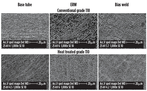
In Fig. 1, microstructures obtained with the new process route are shown and compared with those resulting from the conventional process. Using this new process, major heterogeneities in the microstructure are eliminated. A tempered martensite structure, with fine grains and homogeneous distribution of iron carbides, was observed in base metal and welds. A key aspect of this development is the minimization of macro-segregation effects. For example, the central segregation band can barely be detected by microstructural or microhardness analyses, which can be beneficial for fatigue performance.
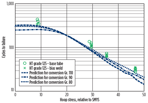
Figure 2 shows the fatigue life as a function of the relative-hoop stress (determined by the inner pressure applied during testing) obtained from laboratory tests on a new heat-treated 125-ksi SMYS grade. Results are presented for samples with and without the bias weld (bias weld and base tube, respectively) and compared with predictions for conventional CT (base tube) obtained with a commercial fatigue software. It was observed that bias weld cycles to failure are practically superimposed on the results for base tube.
The new process has been able to produce high-strength CT, with reduced micro-heterogeneities and, as a result, improved relative fatigue performance of the bias weld, with respect to the base tube.
EXPERIMENTAL RESULTS
Materials. Seven grades of CT were involved in this first stage of the sour testing program: grades 80, 90 and 110 of conventional CT and grades 80, 100, 110 and 125 of heat-treated CT. Samples were taken from commercial strings in the case of conventional grades (with diameters from 1½ in. to 2 in. and wall thickness from 0.190 in. to 0.204 in.), and from industrial trials of complete strings in the case of heat-treated products, 100 to 125 grades (2-in. diameter and 0.190-in. wall thickness). Grade 80 was obtained by re-tempering a 2⅜-in. x 0.190 in., grade 110 heat-treated CT in a laboratory furnace. Conventional products are based on ASTM A606 Type 4 steel (similar to UNS K12043) and heat-treated products on a medium carbon-manganese steel with B-Ti addition (UNS H15211 type).
C-ring tests. To make a comparative analysis of the SSC resistances of the different materials, primary emphasis was put on the ERW seam performance. C-ring diameters ranged from 1½ in. to 2 in., and width was maintained in the range of 25–30 mm. Ring surfaces were machined to remove the as-fabricated surface, following TM0177 paragraph 10.2.4, resulting in thickness between 4 mm and 5 mm. Three different environments were used in C-ring testing, all corresponding to Region 3 severity according to NACE MR0175/ISO 15156. For those environments, partial pressure of H2S was in the range 3 to 100 kPa and pH varied between 2.7 and 3.5. Duration of tests was 30 days, at room temperature. The applied load was 90% of the Specified Minimum Yield Strength (SMYS).
HIC testing. HIC can take place in steels immersed in sour environments in the absence of any load. Both conventional and heat-treated grades were tested following NACE Standard TM0284. Two environments were selected for initial HIC performance evaluation. Environment HIC 1 corresponded to Region 2 of NACE MR0175/ISO 15156 with an H2S partial pressure of 1.4 kPa and pH 3.7. Environment HIC 2 was more severe, Region 3, with 7 kPa of H2S and pH 3.7. Duration of tests was seven days, at room temperature. Samples taken from base tube, ERW and bias weld were tested.
Fatigue testing after sour exposure. The samples were fatigue-tested in the machine designed to reproduce the bending conditions during field operations. During the test, the specimens (tube pieces 6-ft long) were clamped on one end, while an alternative force is applied by a hydraulic actuator on the opposite end. Fatigue cycles were applied by bending the test specimen over a curved mandrel of fixed radius, and then straightening it against a straight backstop. Cycling was conducted with the specimen filled with water at a constant internal pressure until it failed. The test stopped when a loss of internal pressure occurred, due to the development of a crack through the wall thickness (failure).
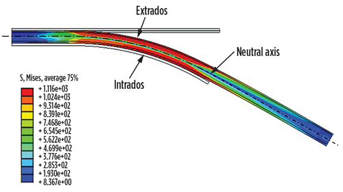
The stress and strain developed during each cycle are not uniform in the tubular sample, Fig. 3. The material is subjected to plastic strain in axial direction by bending, which is maximum on the fibers far from the neutral axis. In addition, the maximum strain is not uniform along the sample, but it is concentrated on the zone that is in contact with the curved mandrel. Therefore, since mechanical properties in the welds can be different from the base tube, the circumferential location of the ERW seam with respect to the bending plane (neutral, intrados or extrados) and the location of the bias weld (when present), relative to the curved mandrel, are also key parameters that affect the test results. Fatigue testing after sour exposure basically consisted of:
- Exposure of 6-ft CT pieces to a sour environment; capped ends were used to have only material-solution contact in the outer surface of the tubing, to better represent typical operating conditions.
- After exposure, the samples were packed in dry ice and transported to the fatigue test machine location, where the caps were removed and replaced by high-pressure caps (to permit internal pressurization to generate the required hoop stress).
- Fatigue testing until failure (through-wall crack propagation).
All fatigue tests were carried out with a bending radius of 42 in. For each batch, two samples were tested at low internal pressure (2,500 psi) and two at high internal pressure (8,000 psi). Number of cycles at which reduction of pressure took place (indicating a leak) was registered and position/dimension of crack (or cracks, if multiple) measured.
A total of six batches was tested, each one comprising the exposure at ambient temperature of four specimens. Half of the specimens corresponded to samples containing bias weld (batches B, D and F). Exposure time was seven days, except in batch A, where the total time was 13 days. Environments were basically the same previously described under HIC testing.
RESULTS
C-ring testing. In this program, failures can be classified in two different groups:
- Complete separation of the ring or conspicuous, visual evidence of cracks penetrating into the material.
- No separation or obvious manifestation of cracks, but the presence of crack-like features, evident by visual inspection. In these cases, sectioning was carried out for metallurgical evaluation to analyze crack morphology and extension.
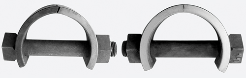
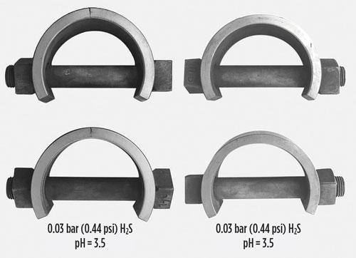
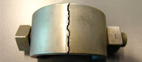
Figure 4 show examples of the first group.
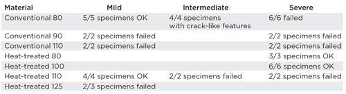
In Table 1, results of testing are listed by material, with a description of results. Empty cells indicate material-test condition combinations that were not tested. A specimen is considered to be OK when “no cracks,” “no visual observation of surface cracks” and “no presence of crack-like feature” are verified.
To illustrate obtained results, in Fig. 5, conventional and heat-treated, grade 110 C-rings, tested at mild condition, are shown after testing. The different performance between conventional and heat treated samples is evident.
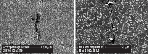
Some selected samples were metallographically examined after testing. Sectioning, polishing and etching were carried out prior to SEM evaluation. Conventional product grade 80, tested in Intermediate severity environment, showed crack-like features on the surface (Fig. 6, left). After sectioning, internal cracks were found associated to these features (Fig. 6, right). SEM analysis was complemented with low magnification observation, and the crack appeared to be in the ferrite (ERW) line. The specimens were considered as failed.
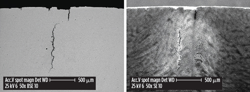
Sectioning was also carried out on a heat-treated, grade 100 sample tested in severe condition, which showed a cluster of several pits at the C-ring apex. This was the only sample of such material showing this type of attack. Pits could act as stress raisers, and there is a potential risk for crack initiation, due to its presence. SEM analysis showed that a crack was associated with the pits. In Fig. 7 (left), a crack starting on the surface initially propagated in the radial direction, and then a change of propagation plane is evident. Relating the crack with the ERW position and characteristics, it initially follows the ERW line and the change of direction appeared to be associated to forging lines (Fig. 7, right). If only the visual evaluation criteria required by NACE TM0177 method C were applied, this sample would pass successfully the test. However, detailed microscopy indicated the susceptibility of this grade to cracking under such test conditions.
When the rings are observed from top (Fig. 8), the cracks were not of a “knife line attack” type, but they jump into different zones of the ERW area. In the metallographic analysis, an intersection of crack plane and sectioning plane is observed, and a crack could appear following the ERW line, or apart from it, depending on the position at which sectioning was performed. This “erratic” character of the cracks could indicate that there is not a single, specific preferential pattern for propagation in the ERW, but both ERW line and segregation lines are similarly susceptible.
Among other reasons, the lack of multiple-cyclic plastic strain performed on CT materials during method C makes it difficult to extrapolate these results to real-service conditions. Even with this limitation, the results show that the metallurgical changes introduced during heat treatment are conclusively improving the SSC performance of the CT. From C-ring results and analysis, materials can be ranked from best to worst:
Heat-treated 80>Heat-treated 100>Conv. 80>Heat-treated 110>Heat-treated 125≥Conv 90>Conv. 110.
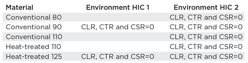
HIC testing. HIC results were the same for all tested materials, positions and conditions, as summarized in Table 2. No cracks were observed after sectioning the different specimens and following the analysis protocol described by NACE TM0284. These results are encouraging, considering that tested materials were fabricated by using flat-rolled products, where segregated areas enriched in some elements at mid-thickness (centerline segregation) are known to be of typical concern for HIC performance.
As mentioned in the description of tested materials, all of the conventional and heat-treated grades presented a low-inclusion content. Basically, they were free of large manganese sulfides (known to be one the main factors for HIC initiation), because of the low-sulphur content and calcium treatment. This could be one of the reasons for the good results.
In the case of heat-treated materials, where a full body treatment is carried out to obtain tempered martensite, homogenization of the microstructure can be seen as a factor to improve HIC performance by avoiding hard spots in centerline segregation (such as non-tempered martensite or bainite and heavy pearlite). The next step of the program will be focused on the evaluation of same CT products in a more demanding environment, in terms of pH and H2S partial pressure, with the idea of identifying areas of improvement for both steel and processes.
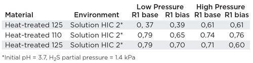
Fatigue testing. The results are expressed as fatigue life, relative to the fatigue life of the same tube in an “inert” condition (CT fatigue testing in air, referred as “sweet life”, with life measured in cycles to failure), at same fatigue testing conditions, Table 3. This relative life is expressed as a ratio, R1=Sour life/Sweet life. Ratios were calculated for both samples containing bias weld (R1 bias) and those corresponding to the base tube (R1 base).
Except for grade 125 tested at low pressure, the relative life of the exposed samples is 60% or higher. This de-rating of 40% maximum is comparable to results obtained for the bias weld of the conventional CT tested without exposure. In the case of the low-pressure test of grade 125, its high strength seemed to play a detrimental role in maintaining a good fatigue performance after exposure. Results are also in line with the ones obtained in the HIC program—relative lives are consistent, with no HIC occurrence.
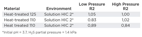
One of the program’s main objectives consisted of evaluating the effect of the bias weld on the fatigue life after sour exposure. We can define a second ratio, R2, to account for this relative performance: R2=sour life for bias tube/sour life for base tube, Table 4.
From this limited group of results, it is clear that fatigue life de-rating, due to the presence of a bias weld, is lower than 20% (relative life higher than 80%). The expected de-rating for high strength conventional products could be much higher, according to previous research. This is a result that shows the positive influence of the heat treatment, which tends to equalize microstructures in the different parts of the string. Other outcomes of the program are:
- Cracks appeared mainly at intrados and extrados, regardless of the position of the ERW. When cracks took place at the ERW, the number of cycles to failure was similar to the ones for cracks in base metal.
- For bias weld samples, some of the cracks were related to the bias weld (40%), and the rest were located either on base metal or ERW. No influence of the bias weld presence on number of cycles-to-failure was observed.
CONCLUSIONS
Full-body heat treatment of CT to obtain tempered martensite in base metal and welds, and to homogenize microstructures, appears to be an effective solution to improve serviceability. Results of testing to evaluate different mechanisms that could damage the product in the presence of a sour environment indicate a positive effect of heat treatment. In particular, the SSC performance of heat-treated CT was markedly better than conventional CT. The possibility to increase about 20 ksi in tube strength, without impairing sour performance, was observed. ![]()
- Coiled tubing drilling’s role in the energy transition (March 2024)
- What's new in production (February 2024)
- Digital tool kit enhances real-time decision-making to improve drilling efficiency and performance (February 2024)
- E&P outside the U.S. maintains a disciplined pace (February 2024)
- U.S. operators reduce activity as crude prices plunge (February 2024)
- U.S. producing gas wells increase despite low prices (February 2024)

