 |
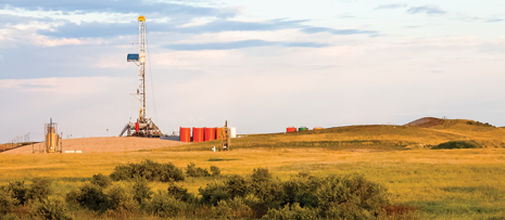
| Drilling the “perfect” well, especially in tricky shale plays like the Bakken of North Dakota, requires close cooperation and good communication between engineers and geoscientists, as well as applying the right tools to the project (photo courtesy of Marathon Oil). |
|
The personas of engineers and geoscientists are often very different. And when it comes to corporate risk assessment and reward systems, company incentives for these individuals can be counterproductive to meeting corporate objectives, such as attaining the highest IP in a play and achieving superior well performance, as compared to their peer group and competitors. For example, drilling team metrics and service company personnel objectives may be polar-opposite to geology’s goal of attaining pinpoint formation zone landings and then maintaining geologic target objectives to TD (i.e. landing and staying in zone). Consequently, team members often miss corporate goals for achieving the best possible investment results, due to conflicts or unrecognized trade-offs required between departmental domains.
Sometimes, competing divergent drivers, and inherent personality differences within the asset team and other well-operations participants, can create obvious conflict and ultimately result in a dysfunctional group. The outcome can be a breakdown of the team, due to many factors, including individual incentives, personalities or, very simply, personal motivation. The ultimate outcome may be significant conflict between otherwise closely aligned team members and service company participants.
The following article explores how to overcome these challenges, and highlights some simple concepts that will help engineers and geoscientists achieve the company’s ultimate goals together. Understanding some basic drilling (engineering) and geosteering (geological) principles and trade-offs is featured, along with some recommended best practices for drilling the “perfect horizontal well.”
COMMON E&P DRIVERS
A horizontal well project’s economic drivers are pretty consistent across all competing oil and gas companies. Every firm generally shares these goals:
- Safe, lowest-cost wells that feature low (or no) incident reports; less NPT (non-productive time) for drilling and completions (D&C); fastest ROP; lowest D&C costs
- Best overall project economics, including most time in zone; highest IP rates; best EUR; fastest spud-to-production (least time to dollars); and highest ROI.
Many companies have been able to pull their asset team together as a cohesive group that constantly attains corporate goals and continually improves processes. We see evidence of this daily in press releases and industry journals. Here are some excerpts:
- “Approximately 60% of current Haynesville production is attributable to well and rig productivity gains made over the past three years …,” NGI Shale Daily
- “Increased well productivity has been the largest driver of overall productivity gains, accounting for about two-thirds, led initially by higher initial production (IP) rates and more recently by improved decline rates,” NGI Shale Daily
- “… many operators were seeing cycle time for drilling cut in half over the last three years, and down as much as 30% in the last year alone,” EPmag.com, October 2012 (Richard Mason)
- Rig [and drilling best practices] increases over the last three years account for 20% of current production, 1.8 Bcfd or one-third of the total productivity gain …,” NGI Shale Daily
- “… rigs are performing so well in complex well environments that operators can now meet program goals with fewer units,” EPmag.com commentary, October 2012 (Richard Mason)
- “An operator like Marathon, who planned to ramp up to 20 rigs in the Eagle Ford, will now get by with 18, for example,” EPmag.com, commentary, October 2012 (Richard Mason).
THE “AGONY OF DEFEAT”
The above quotes are the result of improvement gained through experience and lessons learned, to constantly refine and enhance drilling and geosteering best practices. And, these apply to an asset team understanding the new unconventional business drivers and working together.
But, what happens when a company is not pulling together and encounters problems that often seem to plague horizontal well projects? Let’s take a look at a fictional project that could occur in a basin near you. In this example, the well was drilled in a remote area in Canada, with very little well control; the closest offset well was more than a mile away. The operating company did have 3D seismic over the area, indicating a consistent regional dip, but without the benefit of time-to-depth correlation from offset wells. The targeted formation landing depth (TVD–true vertical depth) was still somewhat uncertain.
The original well plan was to drill down the regional dip angle at the “best guess” landing TVD (as shown by the dashed black line in Fig. 1) and follow along the plan line.
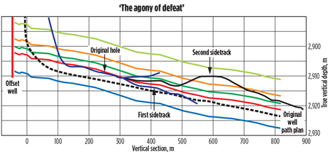 |
| Fig. 1. As the well’s angle built through the curve and landed near lateral, the actual target zone interval proved to be about 6 m shallower than predicted. |
|
As the well’s angle was built up through the curve and landed near lateral (Fig. 1), the actual target zone interval (between the upper orange top and green bottom markers) proved to be about 6 m shallower than predicted; i.e. the planned target landing TVD, estimated from the distant offset well and seismic data time-base correlation. After landing the well, the drilling and geology team hoped that by simply drilling ahead, they would catch up to the regional dip, and the wellbore would track back into zone.
Unfortunately, by overshooting the target and landing in the softer, unconsolidated formation below the target zone, the drill bit’s tendency was to stay in the lower formation and, therefore, it became difficult to break back up into the upper targeted formations. The directional driller (DD) soon realized that the existing drilling assembly (BHA) was not aggressive enough to drill back into the targeted zone; so the drilling team elected to pull out of the hole and pick up a new BHA at about 300 m, vertical section.
After tripping back in with a more aggressive BHA, they were able to cross back upward toward the targeted interval, but then two new problems occurred: the BHA’s resulting dogleg was so severe at the point of formation crossover that 1) the BHA quickly overshot the target zone; and 2) when they were about to drill out of the top of the target, the severe dogleg caused a “twist-off” in their drill pipe at the lower formation crossing point (~310 m). The resulting “fish” was obviously due to extreme stress and bends on the drillstring at the highest point of drillstring fatigue; i.e. where the most severe dogleg was present.
Then, after several days of fishing for the lost BHA, plus a scheduled crew change, the new DD arrived on location with the drilling manager’s strict orders to “get this well back on plan!” And that is exactly what the DD set out to do, as the first sidetrack illustration indicates—a faster ROP and right on target; at least, that is what the DD thought. Unfortunately, the new DD was not told that the new target objective was now more than 10 m higher than the original well path plan. This time, as can often be the case, key team members were absent or otherwise occupied. It was not until they had drilled 250 m laterally that it was discovered that the rapid ROP in the lateral interval had missed the objective totally— blissfully close to the original line; but to the chagrin of the entire asset team, entirely out of zone!
Consequently, another, second sidetrack was called for, this time by the operations geologist responsible for getting the well back into zone and staying in the pre-defined geological target interval. So, after a very long, torturous asset team meeting with the drilling and the geosciences members, to ensure that everyone was finally on the same page, the second sidetrack was kicked off, and real progress to the target objective was finally achieved, albeit briefly. So, yet again, poor targeting practices and an overly aggressive BHA and drill bit created directional control problems. Again, the team found itself far out of zone—this time well above the target.
It was at this time (see the tip of the arrow in Fig. 1 pointing to the “second sidetrack” annotation) that a commercial geosteering company was called upon to provide guidance, to get the well back on target and to stay in zone. The service company’s best practices proved to be a blessing for salvaging as much of the well’s pay zone as possible, yielding a measured success for this exploration well. There was enough early production to warrant another well in the area, which proved to be an economic play. Had the team not been able to prove up this well’s vitality with expert geosteering guidance, and ultimately reached and stayed in zone, the operating company could very well have made the call to walk away from what later proved to be a very economic prospect and, ultimately, a big winner for the corporation.
LESSONS LEARNED
Let’s now consider just four basic guidelines (from many, many possibilities) for safely navigating the perils of horizontal drilling and avoiding the “Agony of Defeat”:
- The BHA will most likely not perform as planned
- Wellbore position uncertainty exacerbates the problem of landing the well in zone
- Targeting methodology is critical to smoother wellbores and staying in zone
- Effective intra-company (and inter-company) communications are essential.
BOTTOMHOLE ASSEMBLY SELECTION
“Achieving a successful, efficient, high dog-leg severity (DLS) can exponentially improve the performance and payout of an individual well.”1 Unfortunately, by design, horizontal wells call for high DLS assemblies that can be inherently problematic for many reasons. The most obvious complications from HDLS drilling assemblies are the rotational, tensile and compressive forces imposed upon an otherwise rigid drillstring and BHA.
To further compound the problem, many directional service companies will err in favor of the most aggressive BHAs—especially in the curve—to provide directional drilling correction capabilities, if they fall behind or require course changes, due to unexpected formation structure or fault crossings. Furthermore, “fatigue life reduces exponentially with increasing build rate,” according to Dunnahoe, and “…catastrophic failure, and twist-off of BHA components can occur…” as was the case in the “Agony of Defeat” example that resulted in the parting of the drill pipe in the HDLS area of the wellbore.
As was also shown in our example above, formation heterogeneity will affect the BUR of the drilling system, requiring trips for BHA changes. A common rule-of-thumb is that the BHA will most likely not perform as expected, so expect and plan for the unexpected. Be sure that your well program has built-in contingencies, wherever possible. Many companies employ a policy of “drill the well on paper” (DWOP) first, with well-rehearsed and tested contingency plans ready to be called upon, when necessary.
UNDERSTANDING WELLBORE POSITION UNCERTAINTY
Problems with determining a wellbore’s actual course and precise location at any given time is well-understood and documented. Yet, many companies do not consider this when making critical decisions in both the planning and execution phases of horizontal wells.
As has been documented in SPE paper 79917, by Stockhausen and Lesso, the magnitude of error of an MWD surveying system in their research has been demonstrated and is illustrated in Fig. 2.
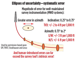 |
| Fig. 2. This illustration, of the magnitude of error of an MWD surveying system, only accounts for the problems of the system, itself. |
|
Of course, this research addresses the problems of MWD system errors, but does not account for the possibility of further human-induced errors. Industry guidelines for quantifying both systematic and random errors are readily available, to better understand and mitigate the impact of these inaccuracies and possibly flawed procedures. These errors are commonly managed in our industry’s “Ellipse of Uncertainty” definition and recommended best practices employed by service companies. Directional service companies quantify these errors and use this information to help operators better understand and manage these inherent errors, especially while drilling an active well.
Now, consider the use of an offset well’s directional surveys for predicting a targeted formation zone for the new, adjacent horizontal well. And also consider that these same offset well data, and directional surveys from other wells in the project, are used to make seismic time-to-depth conversions that are subsequently used to plan and land horizontal wells. These nebulous data may also be used to define the geologic earth model for an entire asset or unconventional resource play.
John deWardt, an industry expert on “wellbore positioning,” and a panelist at SPE’s 2012 Annual Technical Conference & Exhibition in San Antonio, noted that “managers are not asking the right questions to assure safety, well integrity and reserves values.” The panel’s consensus was that “better wellbore positioning, and a better understanding of the reservoir, will lead to improved reservoir models and ultimately improved recovery.” Obviously, caution needs to be exercised in understanding and applying imprecise measurements in all of your company’s projects.
An additional area of wellbore position uncertainty, and an opportunity to improve accuracy, is illustrated below in the sequence of Figs. 3, 4 and 5. These charts illustrate another problem in terms of positional survey intervals, and the survey calculation methodology employed. In these examples, the survey calculation method illustrated is the commonly applied Radius of Curvature model. Yet, the inherent problem described here is present, regardless of the survey calculation method applied.
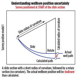 |
| Fig. 3. An additional area of wellbore position uncertainty relates to the commonly applied Radius of Curvature model. |
|
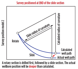 |
| Fig. 4. Here is what happens with the Radius of Curvature model, if the survey is positioned at the end of the slide section. |
|
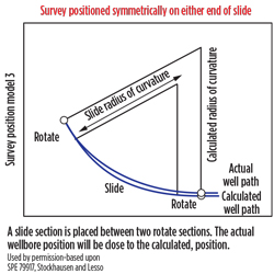 |
| Fig. 5. Drilling the TF-oriented slide interval between two rotating intervals reduces the calculation model error. |
|
The best way to reconcile and minimize these errors is more frequent surveys, especially at the end of any drilling transition zone between “drilling states;” i.e. a change from rotary drilling and sliding (oriented TF) mode or sliding to rotational drilling intervals. As shown in Fig. 5, drilling the TF-oriented slide interval between two rotating intervals reduces the calculation model error. This recommended best practice allows for “drilling out” the curve section and achieving a truer vector orientation at the survey station, rendering the Radius of Curvature model a more accurate representation of the actual well path position.
What should also be understood (and accounted for) is the distance between the MWD sensor system (survey instrument position, housed in the non-magnetic drill collar) and the drilling bit bottom-hole position. Fortunately, the implication of this offset is, again, a well-understood relationship for determining precise wellbore position, which can be modeled in the “actual” well position calculations and may be accounted for in the ellipse of uncertainty definition. Most directional service companies adjust for the measurement position offset when projecting the actual location of the BHA and survey instrumentation verses the actual bit position.
OVERCOMING UNCERTAINTY CHALLENGES
Addressing the above issues is essential to properly identifying the wellbore’s true position in the subsurface, and for the development of an accurate geomodel and determining completion intervals. Fortunately, active horizontal well drilling decisions for landing and staying in the targeted zone (geosteering) can be made, using geologic markers, combined with other important data. Geologic measurements with MWD and LWD tools can be applied independently of the uncertainties of directional survey positioning issues discussed above.
Many directional drillers will argue that they must have directional surveys and an accurate wellbore position to a) plot where they are relative to a well plan; and then b) make good targeting decisions. While the former may be true, if the ultimate goal is to stay within a geologic window or targeted formation zone, then the actual position of the wellbore relative to a geologic marker is the key geo-navigation parameter. In other words, pinpointing the well’s true stratigraphic position (TSP) is really the ultimate objective for the geosteering team. The operations geologist, in concert with the DD and other drilling personnel, must know the wellbore’s precise stratigraphic position at any given moment, a process commonly referred to as geonavigation.
The TSP modeling technique (Fig. 6) is used today by geonavigational specialists to determine the relative position of the logging sensor (typically a gamma ray (GR) detector housed in the MWD system) in the subsurface by using log correlation techniques within specialized software that also provides the expert geonavigator with an apparent formation dip angle. Using these data (TSP and apparent dip), targeting decisions and borehole course corrections may be made, also known as geosteering.
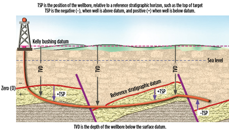 |
| Fig. 6. The TSP modeling technique is used to determine the relative position of the logging sensor in the subsurface. |
|
Utilizing innovative geosteering software and experienced geologists, the geosteering team can accurately track a well’s stratigraphic position, maximize target zone penetration, speed drilling decisions, restrain drilling costs and optimize completions. However, even knowing precisely where you are at any given time, using the TSP navigation technique, the art of geosteering still requires special skills and leveraging certain expertise gained only through years of geologic experience and training.
BASIC GEONAVIGATION PRINCIPLES
These principles include the following items:
- Do not over-react—let your data tell the story.
- Believe average dip, but don’t expect to see it.
- Do not be trapped by pre-conceptions from offset wells and seismic data.
- Acquire more data, including positional surveys, when needed.
- Then use all of your available data for an informed decision.
- Drill to a target line, not to a point in space.
Also, very importantly, what you do with the TSP navigation data, in terms of targeting, can be even more essential. Communicating target changes for execution by the DD is the payoff for applying accurate TSP correlations and following these (and other) geonavigation principles. Therefore, good geosteering, following targeting best practices, is dependent upon the optimal application and communication of the TSP navigational results.
COMMON TARGETING PRACTICES
Many horizontal wells are still drilled by the risky, never-changing “stick with the plan” targeting method. This is a carry-over from offshore or other directional drilling programs, where exploration wells or pilot wells have been drilled, and a single-location target objective was planned. Yes, absolutely, directional drillers can, and do, pride themselves on their ability to accurately hit a target, even miles away from the surface location. Many DDs have been trained for, and have used very successfully, this methodology. However, the application was very different than the geologic target objectives of unconventional resources and geonavigation in horizontal wells, where the number-one goal is to stay in zone.
So, it is not surprising that the “follow the plan” method is still used in areas, where well control is plentiful, and a highly accurate geomodel predicts where a well should be landed and then drilled laterally. However, Fig. 7 illustrates why that can be a dangerous assumption that does not allow for the aforementioned survey inaccuracy problems and those ever-present geologic “surprises.”
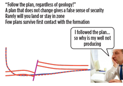 |
| Fig. 7. The “follow the plan” method does not allow for survey inaccuracy problems and ever-present geologic “surprises.” |
|
Another, still very common targeting procedure that is used by geosteerers is the “point-in-space” method. Many companies have even developed an elaborate spreadsheet calculator to determine a 3D position at some predetermined distance ahead of the bit (commonly 500 ft) for the DD to attempt to hit. While this 3D target can usually be achieved by the DD, this methodology does not take into consideration the final well path trajectory at the time the drilling assembly penetrates the point-in-space position.
Most of the time, another course correction is required immediately, to bring the well course back into alignment with the relative formation dip angles and to get back into or stay in zone. The end result is a porpoising wellbore that requires more and more course corrections (sliding) that reduce ROP, add unnecessary torque and drag, produce production bellies, and add complications while running completion strings. This creates future well maintenance problems and unnecessary remedial activity.
In Fig. 8, one can see that a single wellbore path (shown by the dashed blue line) could have been used, rather than three target changes, due to the misalignment of the wellbore trajectory while achieving point-in-space targets.
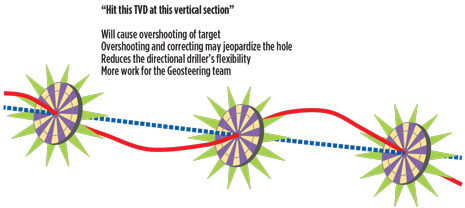 |
| Fig. 8. A single wellbore path (dashed blue line) could have been used, rather than three target changes, caused by misalignment of the wellbore trajectory while achieving point-in-space targets. |
|
Finally, the targeting method that is recommended by this author is the “vector-based” targeting method, Fig. 9. This technique relies on TSP modeling and the recommended best practices already mentioned above (see “Geonavigation Best Practices”).
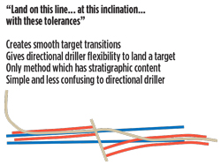 |
| Fig. 9. The “vector-based” targeting method relies on TSP modeling and recommended best practices. |
|
Very simply, the current TSP and apparent dip angles are compared, to determine a new “zero vertical section at a TVD” (VS0 at TVD) position and desired new inclination angle, for use by the DD over whatever course length is required to gradually land on the newly prescribed VS0-TVD angle (vector). Of course, the target vector can be updated easily during the time that the DD is bringing the well path onto a “landing vector” and revised well trajectory. This approach is not too different from the smooth landing of an airplane on a runway. According to Dunnahoe, “borehole quality is fundamental for drilling optimization,” and “a smooth borehole leads to less chance of borehole problems…”2
ASSET TEAM COMMUNICATIONS
The final guideline to avoid the “Agony of Defeat” is the best practice of sound communications across the entire asset team, Fig. 10.
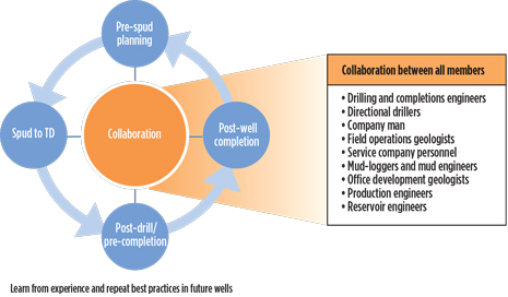 |
| Fig. 10. Practicing sound communications across the entire asset team, as outlined here, can help to avoid the “Agony of Defeat” syndrome. |
|
A few geosteering rules-of-thumb to consider for assuring good communications among the team’s group members include:
- Create an atmosphere of “tribal survival” and sharing information, to leverage everyone’s knowledge and skills, especially your most senior, trusted advisors and service company personnel
- “90% of the hours spent planning and executing drilling projects are accounted for by the service companies’ personnel …,” not by the operating company’s own drilling engineers3
- Yet, the success of horizontal drilling projects is being directly attributed to upfront planning and design work by the E&P company
- Consequently, be sure to include service company personnel in your team, and in all active communications for drilling planning
and execution.
FOSTER A CULTURE OF “TRIBAL SURVIVAL”
Create and support a truly collaborative environment. All team members should be tasked with sharing all information, to leverage the domain skills and individual knowledge of other asset team members. The team’s success depends on relying upon each other and surviving together. And, very critically, be sure to include your service providers.
Furthermore, you should create and nurture an environment of free exchange of data and information. In addition, encourage/reward displays of free thinking and individual expertise; consider everyone’s perspective and exploit their experiences.
RIGHT TOOLS FOR THE JOB
Finally, one more word of advice, bring to bear the appropriate tools to ensure your horizontal project’s success, Fig. 11. These include:
- An appropriate collaboration platform for your team
- Established, well-grounded company drilling (and geosteering) best practices
- Proven, timely communications channels and response protocols
- Integrated, 24/7, drilling and geosteering surveillance
- Robust geosteering software, and an accessible, real-time, drilling data portal
- A highly qualified geosteering team to meet your specific project requirements, that has the right level of expertise and many years of experience.
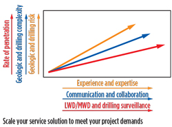 |
| Fig. 11. Using the appropriate tools and service solutions will also help to ensure a horizontal project’s success. |
|
How much of each level depends upon a play’s complexity, challenges and risks. Use of real-time data can be critical to good geosteering decision support, and making decisions proactively and early, rather than having to react and make costly corrections further down the wellbore. Scale your service solutions, to meet the demands and complexity of each project.
CONCLUSIONS
While there are many challenges to drilling the perfect horizontal well, including competing, divergent drivers, and inherent personality differences among the team, following best practices and applying the right tools for meeting project demands will help assure success. This article has provided several guidelines to ensure that asset teams understand each challenge and work together, addressing each barrier and, sometimes, technology limitations.
A few of these best practices include:
- HBUR drilling assemblies are critical to engineering horizontal wells, but the pitfalls and proper application of these BHAs need to be fully understood
- DWOP planning that thoroughly takes into account contingencies, is important for making quick, sound decisions during drilling
- Understanding wellbore position uncertainty is important in all aspects of well planning and completions engineering. It is critical to geomodel definition, and offset well and seismic data correlation
- Drilling states, in combination with directional survey intervals, are important to reducing wellbore position uncertainty
- TSP modeling is the most effective geonavigation process for ensuring a horizontal well can be geosteered to stay in zone
- Good communications across the asset team while leveraging a robust collaboration platform are essential to a successful project
- Applying the right tools to meet project demands is an important first step in planning and executing an optimal horizontal well.
By working together, across all disciplines, communicating freely and leveraging individual strengths, expertise and experience, your project will have a better chance of achieving the ultimate goal—drilling the “perfect” horizontal well. 
ACKNOWLEDGMENT
This article is based on paper 1894404, presented at the Unconventional Resources Technology Conference, Denver, Colo., Aug. 25-27, 2014. The author would like to acknowledge that Ken Bowdon, and Horizontal Solutions International and its website, are the sources of much of the material for this article.
REFERENCES
1. Dunnahoe, EPmag.com, December 2011.
2. Dunnahoe, EPmag.com, December 2011.
3. Jeremy Greenwood, EPmag.com, November 2011.
|
The author
K. C. OREN is V.P. of sales and marketing at Horizontal Solutions International (HSI), and has 34 years of upstream industry experience. He earned twin BA degrees in chemistry and business management, and mathematics and secondary education, from Michigan State University in 1979 and 1980. Mr. Oren began his industry career at Eastman-Whipstock, and then served in roles of increasing responsibility at Smith International, Teleco, Munro Garrett International, GeoGraphix and GeoStar Solutions. Before joining HSI in 2011, his most recent position was senior manager of technology and innovation–D&C Solutions, at Halliburton/Landmark Graphics. Mr. Oren has authored several technical papers and articles on horizontal well drilling and unconventional resource development. |
|


