Ultrasonic devices improve gas leak detection in challenging environments
Given the wide variety of potential gas leak sources, the development of ultrasonic gas detectors for wellhead applications is an important step in providing effective, efficient coverage, on top of traditional gas detection solutions for challenging environments.
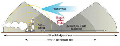
The potential for gas leaks in all types of oil and gas industry facilities is enormous. Refineries, offshore platforms, onshore terminals, underground gas storage facilities, natural gas well pads, and many other sites are vulnerable. All types of gas leaks are possible—hydrocarbon, hydrogen, hydrogen sulfide (H2S) and more. Each type of leak is accompanied by its own safety concerns for plant, personnel or both.In enclosed process environments, where gas releases accumulate, traditional gas detection technologies, such as infrared, catalytic bead and electrochemical-based sensors, perform well. But many gas leaks occur in the open air or ventilated areas, where they disperse rapidly and are diluted to safe levels within a couple dozen feet from the leak source. The danger remains, however, that conditions can change dramatically, extending the area in which LEL (lower explosive limit) and even ppm (parts per million) levels are factors, with gases often building to dangerous concentrations far from the leak source. Even some distance from the original leak, gases that are heavier than air would be able to collect in an unprotected area (e.g., depressions or semi-enclosed spaces). An industry study cites that upwards of 38% of major gas leaks in the North Sea actually go undetected.1 The development of ultrasonic gas detectors (USGDs) provides an effective, efficient layer of coverage (Fig. 1) on top of traditional point and line-of-sight gas detection solutions in these challenging environments, as the wellhead application described below demonstrates.
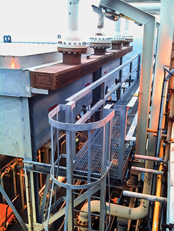
THE ULTRASONIC IDEAThe noise generated by a gas leak comprises both audible and ultrasonic frequencies. The sound is produced, as gas travels from a high-pressure situation to a low-pressure environment. Over time, manufacturers of USGDs have moved away from using broadband devices that also monitor audible frequencies, in favor of true USGDs. Ultrasonic gas leak detection, as its name implies, is a technology that uses acoustic sensors to detect changes in noise within an environment that is outside the scope of human hearing. The sensor and electronics are able to identify these ultrasound frequencies (25-KHz to 100-KHz), while excluding audible frequencies (0-to-25-KHz). This detector “hears” the leak, rather than measuring the accumulated gas. The implementation of the technology is straightforward; the key point being the sound of the leak must be greater than the sound generated by the plant process under normal operation, when the detector is to be installed. Plant background mapping studies or assumptions, based on a wealth of experience from these studies, allows the units to be mounted at strategic locations, close to potential leak points. The coverage afforded by the detectors is then matched to the plant process and can be verified using an inert gas, whose release parameters are designed to reflect that of the true process gas leak. This is something traditional techniques cannot do. The great advantage of the ultrasonic leak detector is that it does not rely on the accumulation of potentially explosive or otherwise dangerous gases to trigger an alarm. The time that it takes to signal an alarm is dependent on the milliseconds required for the ultrasonic noise to reach the detector from the leak, and what settings have been programmed into the device or control system by the user. The technology is ideally suited for use offshore, as well as in normally unattended and remote onshore facilities, or where traditional techniques struggle, such as fin fan coolers. The detectors usually provide coverage in the most likely leak areas, e.g. wellheads, flange joints, compressors, filters, fin fan coolers, heat exchangers and instruments, Fig. 2.
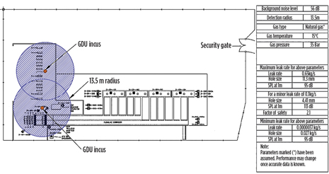
ULTRASONIC LEAK DETECTION IN GAS WELLHEADSOne example situation for an end user that employs ultrasonic leak detection was in pressurized natural gas wellheads, in facilities that are normally unattended. In this particular case, the user needed an alternative to the traditional gas leak detection techniques, given that detector placement was challenging, due to the nature of risk and dispersion characteristics. Two main areas of concern arose, when the firm considered mounting traditional detectors close to wellheads. The first concern was how difficult it would be for operators to access the area for maintenance and repair. In some cases, depending on the set-up, traditional gas detection systems have to be removed for operators to gain access to conduct maintenance. The second concern was the unlikely potential for a gas cloud to accumulate, close to the leak location. Natural gas is much lighter than air and easily disperses when released under pressure. In this application, ultrasonic gas leak detection proved to be an excellent fit, as it could be mounted close to the wellhead, but in such a way that maintenance operations and accessibility were not affected. At the same time, the system could detect the sound generated from a gas leak at the well. After initially trialing the technology, the facility installed further units in their extension facilities. The image in Fig. 3 provides mapping details for the extension facility.
TYPES OF LEAKSIn offshore platforms, the most common leaks are hydrocarbons, particularly methane. These are the types of leaks that often result in jet or spray fires. They can lead to structural damage or worse. Hydrogen is a major process gas in oil refining, and due to its low molecular weight, it has a strong tendency to leak. At present, the primary detection technology used on most facilities is that of the catalytic bead sensor. This technology, although well-established, has some significant drawbacks, including high maintenance and a non-fail-safe failure mode. USGDs offer a real alternative for some hydrogen applications. In sour gas environments, the risk of exposure to H2S can be extremely high. In some parts of the world, concentrations are so high that they will immediately “knock down” personnel, rendering them unconscious, but still inhaling poisonous concentrations, which quickly leads to death. The benefit of USGDs in these environments is obvious, as the speed of response is absolutely critical. USGDs do not discriminate leak types, or sources of ultrasound for that matter, so any type of leak can be monitored, but identifying the potential gas release type, combined with a number of process parameters, will assist in a successful installation. LEAK RATE IMPORTANCETraditional leak detection systems are designed to detect gas accumulations and directly measure gas concentration at the point of installation. This is usually expressed as a percentage of the LEL or ppm. Ultrasonic leak detectors, on the other hand, are essentially sound monitors, and, broadly speaking, detect leak rate. The rate at which gas escapes from a fissure over a specific time period is significant, because a high leak rate indicates the potential for a large gas cloud accumulation, which can result in an explosion or other dangers, in the case of a toxic gas release. Gas leaks are considered “minor” at less than 0.1 Kg/s (2 min.), “significant” at 0.1-1.0 Kg/s (2 to 5 min.) and “major” at over 1.0 Kg/s (greater than 5 min.). These categories are defined by the UK Health and Safety Executive (HSE).2 Despite the fact that USGDs do not measure gas concentration or identify the type of gas, there are parameters by which the mass flowrate of an escaping gas can be determined, but this is not, by any means, an accurate measurement level. The properties of the gas are of particular importance. Whether the gas is heavier or lighter than air, its molecular weight will greatly influence the leak rate. The number of potential combinations of these factors is quite varied and significant. During the mapping phase of a project, there are software packages available that can combine an analysis of the known gas temperature, atmospheric temperature, gas type, pressure, and background noise levels, plus several other factors, to provide figures for the mass flowrate (Kg/s), dB produced at that rate, as well as the detection radius in those conditions. Generally speaking, the larger the fissure size, the greater the leak rate, assuming, of course, that pressure remains constant. This holds true up to a point, but as the size of the leak becomes greater, the ultrasound generated reduces. A simple example of this can be seen, using a party balloon. If we take two identical balloons and inflate them, we can see they have the same volume (reservoir) and pressure in the reservoir. By taking one balloon and pulling the neck tightly, we can produce a very high-pitched sound; these frequencies are tending to move toward ultrasound. If we take the second balloon and simply release it from the neck, we will see the balloon fly around, producing much lower tones, a long way removed from the ultrasonic frequencies. When mapping an installation for the use of ultrasonic detectors, we find that the more modern techniques target device coverage to specific risks, while still referencing the 0.1 Kg/s release rate. By doing this, the detection range is optimized to detect the broadest range of potential leak rates, rather than simply maximizing detection range. AUDIBLE NOISEMany facilities have a wide range of acoustic noise emitted from process equipment, both audible and ultrasonic, Fig. 4. A particularly noisy plant, where there may be turbines, compressors and other types of machinery, can have a constant decibel level upward of 95 dB. This noise level would appear to confound any detection system based on the level of sound. However, most facilities are not generating high levels of ultrasonic frequencies on a regular basis. That being said, the low-level ultrasonic frequencies that are constantly present need to be measured, and accounted for, as background noise within the ultrasonic leak detector settings.
Facilities also frequently have equipment that emits temporary blasts of high-level ultrasound (e.g., pressure relief valves). Users are naturally concerned that these events might trigger unwanted alarms on the ultrasonic leak detector. This challenge is overcome easily by the use of time delays built into the instrument, itself, or in the control system, as a pressure relief valve will not stay open for a significant amount of time. Performing a site evaluation before setting the alarm levels and time delays on USGD systems is critical to confirming the area of coverage for each detector, determining the ideal placement, and eliminating unwanted alarm sources. SETTING UP DETECTION COVERAGEAll of the factors used in determining the coverage of a USGD and setting up placement of detectors can be known in advance of installation. Whether the facility exists or is in the planning stages, a detection coverage plan can be created. The type of facility must first be considered, realizing that every junction and joint in any equipment, such as manifolds, valves, flanges, wellheads, etc., are areas of potential leaks that need to be covered. The type of gas and potential hazard will help to determine the size of leak to be detected. Setting up detection coverage is based on the ultrasonic background noise level of the area, and the size of the leak that the user wants to detect. Detection area increases in very low ultrasonic noise areas, and decreases in noisy areas, as indicated in Fig. 2. The following shows detection coverage in high-, low- and very low-noise environments:
One important point to note is the direction in which the detector is pointing, as this can also affect coverage area, with greatest detection occurring in front, and to the sides, of the USGD, depending on the manufacturer chosen. CONCLUSIONSNo single leak detection method is appropriate for all applications—there is no perfect solution. In many confined areas, a standard point monitoring device for LEL measurement of gas concentration is still the right detector for the job. But, in industrial environments, like offshore and onshore oil and gas platforms, refineries, gas storage facilities, wellheads, and LNG plants and trains, where dangerous leaks can go undetected because of air flow, ventilation or other environmental conditions, the USGD has emerged as a true game-changer. The detectors are extremely robust and reliable. They provide an almost instantaneous response-and-deliver coverage area in even the most challenging environments. And depending on the acoustic sensor employed, they will never require calibration, and the sensor, itself, will never expire. That means there is virtually zero maintenance for the life of the instrument. Combine that with the early warning capabilities and enhanced safety coverage, and the adoption of ultrasonic gas leak detection is expected to become even more widespread, as end-users reap the true benefits of this technology. REFERENCES
|
- What's new in production (February 2024)
- U.S. operators reduce activity as crude prices plunge (February 2024)
- U.S. producing gas wells increase despite low prices (February 2024)
- U.S. oil and natural gas production hits record highs (February 2024)
- Dallas Fed: E&P activity essentially unchanged; optimism wanes as uncertainty jumps (January 2024)
- Enhancing preparedness: The critical role of well control system surveys (December 2023)


