 |
| A set of full fairings positioned on a drilling riser to alleviate the effects of vortex-induced vibration (photo courtesy of VIV Solutions). |
|
When an ocean current flows past a cylindrical object such as a riser, tendon, jumper or horizontal pipeline span, it creates a phenomenon called vortex-induced vibration (VIV). Friction against the cylinder’s surface causes boundary layers to form on each side of the cylinder. The retardation of the flow, due to the friction, ultimately causes the boundary layers to roll up into vortices and separate from the tubular—a process known as vortex shedding. Vortex shedding produces alternating forces on the cylinder, thereby creating VIV. Tubulars experiencing VIV can eventually fail due to fatigue. To prevent substantial fatigue damage, it is helpful to install VIV suppression devices over at least part of the tubular span (to reduce the vibration amplitude and/or frequency). VIV can usually be minimized with the careful selection and design of VIV suppression devices, such as fairings and helical strakes.
Fairings provide protection against VIV forces by streamlining the flow of currents around a tubular, effectively dispersing the vortices that cause oscillating forces on its surface. Fairings are designed to rotate freely around the tubular, and self-orient, with the tail pointing downstream.
To address questions involved in planning configurations for marine risers, and to investigate the impacts of typical conditions affecting VIV, two programs were conducted. These programs consisted of tests along a near-100-ft-long tubular that was towed under a rotating arm at high speeds, to simulate conditions similar to those that a deepwater riser may encounter.
The test results revealed a variety of positive outcomes regarding the performance of fairings, including:
- Increased fairing coverage length decreases VIV, but the reduction is not monotonic with fairing coverage.
- Fairings are most effective for the areas in which they are located.
- Spreading out the fairing coverage, rather than concentrate it over a continuous length.
- Placing fairings where currents are the highest (poor placement is still better than no coverage).
- Low-to-moderate uniform surface roughness decreases fairing effectiveness.
- Both strakes and fairings are very effective at suppressing VIV on a long tubular, but fairings appear to generate a little more damping, and thus provide slightly better suppression with suboptimal coverage.
- By streamlining the flow, fairings can decrease drag significantly.
FAIRING BASICS
Fairings date back to the theory of airfoils. They later evolved into being used on cables of various sizes, shapes and numbers. Fairings for the suppression of VIV on drilling risers and other marine structures began to see usage in the late 1970s.
There are a number of parameters that describe a fairing system:
- Chord-to-thickness ratio (c/t), which defines slenderness
- Height along the cylinder length
- Shape of the fairing sides (straight, curved inward/concave, or curved outward/convex)
- Annulus, defined as distance between the cylinder OD to the inside of the round portion of the fairing body
- The length of the tail flange. This is the area at the tail, where the two fairing sides come together. It is often used for bolting or attaching the two fairing sides together, to prevent the fairing from coming off of the cylinder
- Whether a stabilizer fin is present at the tail (an appurtenance or shape at the fairing tail that at least partially protrudes, normal to the fairing flange)
- Whether the fairing is free to rotate (or weathervane) with changes in the incoming current direction.
When a cylinder experiences vortex shedding, the vortices cause VIV by synchronizing with the cylinder’s natural frequencies, resulting in stronger vortices. Synchronization of the vortex shedding frequency (fs) and structural natural frequency (“lock-in”) also causes the vortices to correlate along the cylinder span, increasing the strength of the vortices and the amplitude of the VIV. Fairings, when properly designed, work by streamlining the incoming flow and providing an after-body to increase the cylinder base pressure. The net effect is both a reduction in VIV and a reduction in the mean drag force. Streamlining delays the formation of vortices, so that much of the shear layers is extended downstream of the fairing tail. The vortices then increase in size, in the wake.
When the cylinder begins to vibrate (there is a bandwidth of frequency for which a cylinder will begin to vibrate, due to vortex shedding), the frequency of vortex shedding can begin to change. This change is typically closer toward the nearest natural frequency of the structure. It is then prudent to designate a different frequency for a vibrating cylinder (fv).
While helical strakes are known to substantially reduce both fs and fv, because of the larger effective diameter of a tubular fitted with tall helical strakes, fairings reduce fs and fv only modestly. The presence of the fairing still increases the effective diameter experienced by the incoming flow, since the fairing width must be larger than the tubular diameter. However, the fairing width is not as large, compared to the width of a cylinder with tall helical strakes (commonly used for deepwater tubulars), and thus the decrease in fs and fv is smaller than that for a tall strake. The approximate, effective diameter for these fairings was 2.94 in., about 17.6% larger than the test cylinder diameter. It is common for helical strakes on deepwater tubulars to have a height of 0.25D (with a relatively long pitch of between 16D and 17.5D), and thus the strakes have an effective diameter that is about 50% larger than the test cylinder diameter.
TEST DESCRIPTION
Both of the test programs were conducted in the Rotating Arm basin at the Naval Surface Warfare Center in Carderock, Md. The basin is a circular indoor tank, approximately 260 ft in. diameter and 20 ft deep. Models were mounted under, and parallel to, the arm and towed in circular paths through still water.
The test pipes at each end were supported by a sophisticated assembly that permitted the ends to rotate while allowing the test pipes to be pre-tensioned to the same value. However the variation of drag on the various models produced different tensions during testing. The tensions were measured at each end, and the accelerations were measured using bi-axial accelerometers at four locations along the pipe axis. These locations were chosen to be in close proximity to the anti-nodes (locations of maximum vibration) for the vibration modes of greatest interest.
The test cylinders were 2.50-in., OD, fiberglass composite pipes and were made in five joints with internal aluminum connectors between joints. The connectors were made to fit inside the main joints (as an inner sleeve) and bolted to the fiberglass to connect adjacent joints. The fairings were made of thin sheet metal (16 gauge) with a thickness of approximately 0.0625 in. The fairings were 2.80 in. wide, with a chord of 3.74 in. Therefore, the fairing chord was 1.5 times the pipe’s OD of 2.5 in., and thus the chord-to-thickness ratio was 1.34 (the chord-to-thickness ratio is simply the fairing chord divided by the fairing thickness, which is the width of the fairing at its widest point). The fairings were 3.0 in. long, in the direction of the pipe axis. A 0.0625-in.-thick (16 gauge) reinforcing piece was inserted on the inside of the fairing annulus near the tail (all fairings tested here had a pointed tail, as opposed to a wide tail). The tails were welded at the tips, and the fairings were slid onto the ends of the test cylinders during installation.
BARE CYLINDER RESULTS
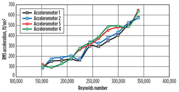
To properly assess the performance of a fairing configuration, the bare cylinder (the cylinder without any fairings present) must first be examined. Figures 1 and 2 present the displacement and acceleration results for a bare cylinder with a relatively low level of roughness (accelerometers 1 and 2 were near the inner end, while accelerometers 3 and 4 were near the outer end). The Reynolds number was chosen for the x-axis. The Reynolds number was chosen because, in some instances, a portion of the test cylinder length experienced critical Reynolds numbers (transition to turbulent boundary layers on the cylinder surface), thereby influencing the results.
 |
| Fig. 1. Bare cylinder displacements and drag coefficients. |
|
 |
| Fig. 2. Bare cylinder accelerations. |
|
These figures illustrate several things:
- The values for adjacent accelerometers were very close; the displacement values varied with the Reynolds numbers (i.e. test velocity) and most likely mode shape, too
- The accelerations increased with increased Reynolds numbers / test velocities, which is not surprising, since the mode numbers and response frequencies are increasing, too
- The accelerations at each end of the pipe varied, but were relatively close in magnitude, indicating that very little attenuation occurred for the bare cylinder
- The drag coefficients decreased slightly with increased Reynolds numbers, most likely due to the entrance of more and more of the cylinder length into the transition region for turbulent boundary layers.
COVERAGE LENGTH
A common difficulty in designing deepwater tubulars, such as risers and tendons, is determining how much of the tubular to cover with VIV suppression devices. Since most deepwater areas have currents that are highest in magnitude nearest the surface, and they decay in magnitude with increased depth, this determination often centers on how far to cover the tubular with suppression devices, in this case fairings.
The test cylinder was next covered with various lengths of fairings, starting with 9 ft, 8 in. of fairing coverage on the outer end. The 9-ft, 8-in. coverage length produced a modest reduction in rms (root-mean-squared) acceleration. The accelerations at the outer end were suppressed more than the accelerations at the inner end, due to the damping imposed by the fairings. At the outer end, the fairings effectively reduced the excitation; however, there was still a large amount of excitation present in the bare region of the cylinder that excites VIV. The excitation in the bare region occurred at a lower frequency, due to the smaller current velocities encountered. This excitation produced larger vibration at the inner end of the cylinder than at the outer end. The fairings also provided strong local damping.
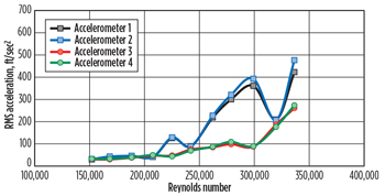
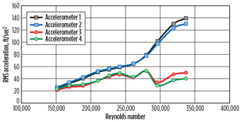
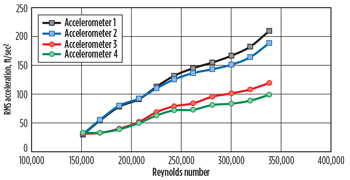
Figures 3 and 4 present the results for 19 ft, 4 in., and 29 ft, of fairing coverage length. The accelerations at the inner end decreased with increased fairing coverage length, but not evenly. There was a large drop in the accelerations between 19 ft, 4 in., of coverage, and 29 ft, where the inner end accelerations drop by about a factor of 2.5.
 |
| Fig. 3. Accelerations for cylinder with fairings on outer 19 ft, 4 in. |
|
 |
| Fig. 4. Accelerations for cylinder with fairings on outer 29 ft. |
|
The accelerations at the outer end also experienced a large drop when the fairing coverage increased from 19 ft, 4 in., to
29 ft. However, the peak accelerations with 38 ft, 8 in., of coverage (not shown) were actually larger than with 29 ft. This may have been caused by the location of the anti-nodes of vibration being closer to the accelerometer locations for the 29 ft, coverage case.
With 38 ft, 8 in., of coverage, the accelerations at the inner end dropped by about a factor of 6 from the bare cylinder values, and the accelerations at the outer end dropped by almost an order of magnitude. This last observation is significant, since it illustrates that a dramatic suppression effect can be obtained with partial (in this case less than half of the length) coverage of a cylinder with fairings.
COVERAGE DENSITY AND LOCATION
While it is important to understand the effect of coverage length on VIV suppression performance, it is also important to understand the effects when less than 100% density of the cylinder is covered with fairings. This may be necessary, due to the presence of riser appurtenances (such as connectors, anodes, etc.), or due to an integer multiple of fairing lengths leaving part of a pipe joint bare.
A comparison of Figs. 3 and 4 shows that the cylinder with fairings spaced apart experienced accelerations that were two to three times lower than the cylinder with the fairings condensed together in one segment. Thus, for a given amount of fairing coverage, these results indicate that it can be prudent to spread those fairings out over broader lengths, rather than bunch them together. This, of course, also depends upon other variables, such as the flow profile, which may not be approximately linearly sheared, such as experienced by this test cylinder.
While coverage length and density are influential parameters in fairing performance, another interesting parameter is fairing location, relative to the incoming currents. Tests were conducted with fairings on the inner two joints (the low speed end) and compared with tests performed with fairings on the outer two joints (the high-speed end). For the accelerometers nearest the inner end of the cylinder, the outcomes from the two fairing locations were fairly similar in overall acceleration magnitude. At the highest test speeds, the configuration with fairings at the inner end actually experienced smaller accelerations than the configuration with fairings at the outer end. Conversely, results for accelerometers closest to the outer end of the test cylinder showed that the configuration with fairings on the outer end had substantially lower accelerations than when the fairings were on the inner end. However, even with fairings on the inner two joints, the accelerations at the outer end of the cylinder were still reduced by a factor of 2-3. Again, this was due to the substantial damping introduced by the fairings. These results illustrate that it is important to place the fairings where the currents are the highest. However, significant benefit can be obtained, even if the fairings are not in an optimal location.
A systematic set of tests was conducted on coverage density, where the fairings on each of the outer two joints were arranged in four groups, each having an approximately equal number of fairings, with a single group at the outer end of each joint and two groups arranged in the center of each joint. As noted previously, the connector region between joints was bare. The fairing density on these outer two joints ranged from 23% to 96%.
The results presented were averaged across all test speeds and for all four accelerometers. They showed:
- The average response frequency was about 70% of the bare cylinder response frequency, regardless of the fairing coverage density
- A sharp decline was experienced in the average displacement and average acceleration until a density of 68% was reached
- There was only a small improvement in the fairing performance, overall, for coverage densities that were larger than 68%.
Results for the displacements were similar to those of the accelerations, and the frequency results had very little variation between the four accelerometers.
FAIRINGS VERSUS STRAKES
The choice between strakes and fairings can be difficult. Helical strakes are known to be slightly more economical, a little more popular, and they do not require the ability to weathervane around the tubular. Fairings produce lower mean drag forces and tend to perform better on downstream tubulars. They have grown in popularity, as the industry marches into ultra-deepwater areas.
Bare cylinder tests were conducted with tubulars, both fully covered with fairings and fully covered with helical strakes. The helical strakes were triple-start strakes, with a height of 0.25D and a pitch (per start) of 17.5D. The isolated tubulars covered with smooth fairings or smooth strakes experienced very low VIV, making both fairings and helical strakes an excellent choice. The differences in their performance are extremely small (many of the differences may simply be due to the location of the accelerometers relative to the vibration anti-nodes), and both reduced accelerations by well over a factor of 10 at both ends.
These results for tubulars with partial coverage indicate a preference for fairings in terms of VIV suppression performance. While some tests with shorter amounts of coverage showed helical strakes having an advantage, fairings seem to perform better, when a substantial amount of the highest current region is covered.
DRAG CONSIDERATIONS
The drag coefficients of fairings are influenced strongly by a number of parameters, including the fairing geometry, the Reynolds number, and the vibration response (which is a function of the fairing efficiency, coverage, density, and surface roughness).
Drag coefficients for a test cylinder, fully covered with fairings, were compared with those of a bare cylinder and a cylinder fully covered with helical strakes. The helical strakes were quad-start (four starts instead of three) versions, with a height of 0.25D and a pitch (per start) of 17.5D.
Results found that fairings reduce the drag forces below the levels of a bare cylinder. Further, other tests performed with fairings that have a higher chord-to-thickness ratio produced even lower drag coefficients. Therefore, fairings have distinctly lower drag coefficients than strakes. While tests on similar strakes with three starts have produced lower drag coefficients than those for the quad-start strakes, the coefficients were still almost twice those for fairings.
The bare test cylinder also had fairly low drag, especially since it was experiencing large VIV. This was due, apparently, to the bare test cylinder having a relatively low surface roughness (which causes low drag when the cylinder is stationary), but the surface was not sufficiently smooth to significantly reduce VIV. Thus, the drag increased well above what would be expected, if the cylinder was stationary, but was still fairly low, especially compared to drag coefficients for helical strakes.
CONCLUSION
These tests served to provide insight into various aspects of fairing coverage length and density for practical tubulars. By utilizing the data for model calibration and for practical decision-making, safer design of deepwater tubulars can be achieved. 
ACKNOWLEDGMENT
This article has been derived from a paper presented to the ASME 33rd International Conference on Ocean, Offshore and Arctic Engineering, San Francisco, Calif., June 2014.
|


