 |
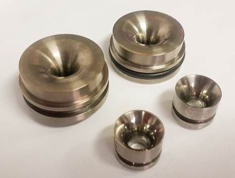
| Nozzle valves of different sizes were tested in experimental lab and field settings. Photo by A.R. Dortas. |
|
Two types of gas-lift valves are used. In the first type, there is a mechanism to open or close the valve, according to pressure and/or temperature conditions in the well. A charged bellows is the most common mechanism. The second type is valves that are always open (in the casing-to-tubing direction). These valves employ a choke to restrict flowrate and a check valve to avoid reverse flow from tubing to casing. The most commonly used choke is a cylindrical plate with a square-edge orifice. Alternatively, a choke with Venturi geometry may be used. These valves are commonly called orifice or Venturi (or Venturi-nozzle) valves. Typically, the charged bellows type is used as discharge valves, while the operating valves are of the orifice or Venturi type.
The Venturi valve has been seen as a direct competitor to traditional orifice valves. In theory, while every well producing by (continuous) gas lift may be equipped with Venturi valves, in practice, however, some factors may prevail to suggest a preference for orifice valves. In fact, orifice and Venturi valves are complementary technologies.
Designers of gas-lift strings appreciate advantageous aspects of the Venturi valve (e.g., control of casing heading instability, higher gas flowrate, deeper injection point, better well control in dual completions, etc.) with a disadvantage, in some cases, in terms of sensitivity to gas injection pressure.1 Thus, even though primitive, the orifice valves survive in the application of continuous gas lift, without a direct competitor that meets desired characteristics for certain applications, and provides additional advantages.
NOZZLE VALVE CONCEPT
Figure 1 shows performance curves comparing the flow behavior of the three types of valves: orifice, nozzle and Venturi. A commercial, 1½-in.-OD Venturi valve was used, and three elements were manufactured with the same material (titanium), same minimum passage area (5.2-mm diameter), and the same dimensional tolerances and finishing. In this figure, the black curve refers to a full Venturi valve, similar to its commercial counterpart, except for the material of the Venturi, itself. The blue curve refers to a convergent nozzle, equal to the nozzle of the previous Venturi (i.e., as if it were cut exactly at the Venturi throat, separating nozzle from diffuser). Finally, the red curve refers to a square-edge orifice plate, with a thickness equal to the previously cited nozzle element.
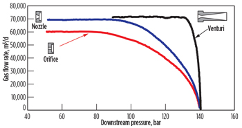 |
| Fig. 1. Dynamic performance comparison among Venturi, orifice and nozzle valves at standard conditions (atmospheric pressure and 20°C). The curves were obtained at Petrobras’ Gas Lift Test Unit (UTVGL) in Aracaju, Brazil, with natural gas and 140-bar upstream gauge pressure. |
|
On the one hand, Fig. 1 shows the well-known comparison between Venturi and orifice in terms of dynamic behavior. For a given upstream pressure, the Venturi establishes the critical flow at a much higher downstream pressure than that required for the orifice plate. The subcritical region in the Venturi’s performance curve is considerably narrower than that in the orifice curve. This means that, under normal operating conditions, Venturi valves operate in critical flow, and orifice valves in subcritical flow. In mathematical terms, the critical pressure ratio, i.e., the ratio between the downstream pressure required to reach critical flow and the (fixed) upstream pressure, is greater for the Venturi than for the orifice valve. Typically, the critical ratio for a well-designed Venturi valve is 0.90 to 0.95, and for the orifice valve is 0.55 to 0.65. The Venturi also provides a critical flowrate substantially higher than that of the orifice, although the diameter of the throat/orifice is the same in both cases. The sudden contraction in gas flow, after the orifice, provokes the so-called vena contracta phenomenon. Thus, the smallest flow area is not the orifice area itself, but that of the vena contracta. The smooth geometry at the nozzle of the Venturi promotes a flow closer to the ideal isentropic flow and prevents vena contracta formation. Again, in mathematical terms, the discharge coefficient, i.e., the ratio between the actual flowrate and the theoretical ideal flowrate, is higher for the Venturi than for the orifice. Typically, this ratio is around 1.0 for the Venturi and around 0.85 for the orifice.
On the other hand, Fig. 1 also shows that the nozzle valve exhibits behavior intermediate between the orifice and the Venturi. It behaves similarly to an orifice, in terms of critical pressure ratio, and similar to a Venturi in terms of discharge coefficient, thus combining key aspects of both elements. In relation to the orifice plate, the nozzle valve allows for more accurate modeling, since the gas flow approaches the ideal isentropic flow, and the vena contracta is not present. In relation to the Venturi, the nozzle valve allows for operation in subcritical flow, which means an increased sensitivity to casing pressure. Moreover, the nozzle is less susceptible to erosion and breaks, common in sharp-edged orifice plates, which may introduce unpredictable changes in dynamic behavior, along with other problems.
Thus, the nozzle valve appears as an ideal substitute for the orifice plate in gas-lift valves.2 It exhibits the sensitivity to injection pressure, desired by some designers in certain applications, besides a smooth convergent geometry, allowing for a more accurate modeling (discharge coefficient close to 1.0 and a more predictable downstream pressure recovery).
MODEL TO CALCULATE FLOWRATES
For Venturi valves, an accurate model was developed for calculating the critical flowrate, considering the isentropic gas flow through the nozzle.3 For this type of valve, the interest is focused on the critical flow rate. It is not expected, nor advisable, to operate a Venturi valve in subcritical flow. Thus, it is sufficient to calculate the critical flow rate as a function of gas type and upstream pressure and temperature. The critical ratio of the overall valve, in turn, can be determined experimentally. With this information in hand, the designer has all the information he needs to size the valve for a specific well. The valve is positioned at a depth where there is sufficient differential pressure to ensure critical flow and the throat diameter is calculated to pass the desired gas flow rate. It is not essential to accurately model the subcritical region, and therefore, it did not receive much attention.
The case of the nozzle valve is different. The operation usually occurs in subcritical flow. Figure 2 illustrates the pressure profile across the valve in this situation. Point 1 is the nozzle inlet plane, and the pressure, P1, is basically the casing pressure at the valve depth (neglecting pressure drop at inlet ports of the mandrel and of the valve, itself). Point 2 is the throat of the nozzle, and point 3 is the valve exit. Pressure, P3, is basically the tubing pressure at the valve depth (neglecting pressure drop at outlet ports and at the check valve).
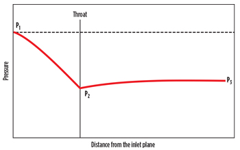 |
| Fig. 2. Pressure profiles along the gas path through a nozzle valve. |
|
Due to the smooth geometry of the nozzle, the gas flow until the throat can be considered isentropic and evolving from P1 to P2. However, there is a pressure recovery (though small) between the throat and the valve exit, and then it is necessary to find a way of estimating P2 as a function of P3, which is the pressure actually known or estimated by simulation. One approach for this is to assume that the pressure recovery factor, FPR, defined by Eq. (1),

is constant and dependent only on the throat diameter.
A rigorous model for subcritical isentropic flow of real gases in nozzles was developed by the author based on an existing model for critical flow in Venturi valves.3 A more comprehensive model will be published in a future article. However, ref. 3 indicates that the traditional Thornhill-Craver equation, in its modified form, provides reasonable results (± 5% error) for casing pressures up to 150 bar, and temperatures usually found in oil wells, if properly calibrated with consistent experimental data. The modified Thornhill-Craver equation can be written as Eq. (2):

Where:
Qvgp = gas flowrate at standard conditions (atmospheric pressure and 20°C) in m3/d
P1 = upstream (casing) absolute pressure, bar
A2 = throat area, mm2
z1 = gas compressibility factor for upstream conditions
θ1 = upstream (casing), absolute temperature in K
dg = gas specific gravity (air = 1.0)
ζ = ratio of specific heats, cP/cV (for natural gas it is usual to adopt ζ ≈ 1.3)
Ψp2 = P2/P1, ratio between throat absolute pressure, P2, and upstream absolute pressure P1.
The discharge coefficient, Cd, is a correction factor to account for deviations from the hypotheses used to deduce Eq. (2). It is obtained from experimental tests.
Given a FPR, pressure P2 may be calculated from P1 and P3. If P1 is constant, and P3 is continuously reduced, the pressure at the throat, P2, is continuously diminished. The flowrate increases until P2 reaches the critical pressure, P2c, for which the velocity at the throat is sonic, and any further reduction in P3 does not change P2 or the flowrate. A shock will happen, somewhere after the throat, to accommodate pressure change from P2 to P3. In terms of Eq. (2), it means that if the calculated P2, using P3 and FPR, is lower than P2c, then Ψp2 is to be replaced by Ψp2c = P2c /P1, the critical pressure ratio. The theoretical critical ratio, Ψp2c, considering the hypothesis involved in Eq. (2), may be obtained by differentiating it with respect to Ψp2, and equaling it to zero (since Ψp2c is the Ψp2 ratio for which the flowrate is maximum) which yields:

using the typical value ζ=1.3, Ψp2c = 0.54.
For example, consider a gas-lift valve with a nozzle that has an 8-mm throat (A2 = 50.26 mm2). The absolute upstream and downstream pressures are P1 = 100 bar and P3 = 80 bar, respectively. The upstream temperature is θ1 = 335 K, and the natural gas has a specific gravity, dg = 0.70. From experimental tests, a discharge coefficient, Cd = 0.98, and a pressure recovery factor, FPR = 0.20, were established for this type of valve. Then, the corresponding pressure P2 = 75 bar, may be obtained from Eq. (1), and Ψp2 = 75/100 = 0.75. The upstream compressibility factor may be estimated as 0.8341 for the given conditions, and the gas flowrate may be estimated, using Eq. (2) as:

If the downstream pressure, P3, is reduced to 56 bar, P2 calculated from Eq. (1) is 45 bar, and Ψp2 = 45/100 = 0.45 < 0.54. Then, sonic flow is established at the throat, and the critical flowrate, Qvgpc, is calculated using Eq. (2), with Ψp2 = Ψp2c = 0.54 as

One of the hypotheses to deduce Eq. (2) is that Ψa, the area ratio between the throat/orifice area and upstream area, is negligible. It means that the kinetic energy upstream of the valve may be disregarded, i.e. the conditions (temperature and pressure) given at point 1 are those of stagnation. Since the area of the annulus casing-tubing is, in general, much larger than that of the main restriction in a gas lift valve, it is a valid hypothesis. Take care, however, with experimental installations or other applications, where Ψa, if relevant, will influence the calculation of both gas flowrate and critical ratio.
Although described here for the nozzle valve, the model may be used for Venturi valves, as well (in this case, FPR is typically 0.80-0.90). For orifice valves, the model still works, but the parameters, FPR and Cd, vary in a less predictable way, since the upstream pressure and small geometric details (presence and size of bevels, for example) are also influential in terms of their values.
EXPERIMENTAL AND FIELD TESTS
To evaluate the nozzle valve concept, some prototypes were manufactured and submitted to experimental and field tests. For the sake of simplicity and reliability, the prototypes were adapted from commercial Venturi valves, i.e, the original Venturis were replaced by specially manufactured nozzles. Then, attention was focused on the behavior of the new element, the other parts of the prototype functioning normally, as in commercial valves. Another advantage of this strategy is that the Venturi valve has a check valve that interferes less in the gas flow and introduces low head loss. The several nozzles tested followed the basic toroidal geometry, described in standards as the ASME MFC-3M-2004 (ISA 1932 nozzle).
At first, a series of nozzles with the same throat diameter, but with different geometric details (throat length, for example) were tested to evaluate the best nozzle profile. In this case, a 1½-in OD, adapted Venturi valve was employed, and the tests were performed at Petrobras’ Gas Lift Valve Test Unit (UTVGL) in Aracaju, Brazil. The mathematical model, and an algorithm to calculate the match parameters, FPR and Cd, were developed at this time. Once the concept and the model proved to be consistent, a field trial was planned.
Because of its similarity with conventional orifice or Venturi valves, there was no reason to expect that the nozzle valve would present any limiting operational issue. Nevertheless, it is a common and advisable practice to test new equipment in real oil or gas wells for a representative period of time before considering it ready for commercial use.
For the field test, an onshore oil well producing with continuous gas lift was selected, and a prototype was built on a 1-in. OD, commercial Venturi valve, replacing the Venturi with a 6 mm-throat nozzle. Performance curves for this field prototype were obtained at Petrobras’ UTVGL and are shown in Fig. 3. The model presented here was fitted, using FPR = 0.16 and Cd = 0.99, with excellent results (using the more rigorous model, FPR = 0.16 and Cd = 1.0).
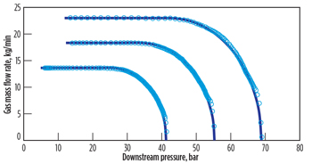 |
| Fig. 3. Dynamic performance of the nozzle valve prototype used in the field test. The experimental curves (gray circles) were obtained at Petrobras’ UTVGL with natural gas. The theoretical curves (black lines) were calculated with the modified Thornhill-Craver model, considering FPR = 0.16 and Cd = 0.99. |
|
The nozzle valve was run in the selected well during July 2012 by wireline intervention, and set at a 1,125-m depth inside a 2⅜-in. side pocket mandrel, replacing a ¼-in. orifice valve. At that time, the well produced 19 cmd of oil (41°API) and 9 cmd of water. The casing pressure was 32 bar, and about 12,000 cmd of lift gas were being injected through the nozzle valve. No operational problem has been reported since then.
A NEW DESIGN PARAMETER
At this time, the gas-lift designer is forced to choose between two extremes: a Venturi valve or an orifice valve. On one hand, the Venturi valve has a very high critical ratio, and a discharge coefficient close to unity, but a limited ability to adjust the gas flowrate, based on casing pressure adjustments. On the other hand, an orifice valve has a low critical ratio and poor discharge coefficient, but a reasonable operational flexibility in terms of gas flowrate.
The nozzle valve corrects the discharge coefficient, approaching it to unity, and maintains the full operational flexibility of an orifice valve, because the critical ratio remains basically the same. The designer is still limited to choose between a valve with virtually no pressure recovery downstream of the restriction, or a valve with almost full pressure recovery. However, this is not mandatory. In fact, the pressure differential between annular and tubing required to achieve critical flow through the valve may be a design parameter. This may be achieved, for example, by changing the diffuser half-angle of the Venturi to obtain the prescribed critical ratio. Figure 4 shows the effect of such an angle on the overall behavior of the Venturi.
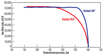 |
| Fig. 4. Dynamic performance comparison between a “normal” Venturi with a diffuser half-angle equal to 6° (blue curve) and a similar Venturi with the diffuser half-angle equal to 12° (red curve). Both Venturis have the same nozzle geometry and a throat diameter of 5.2 mm. Note the influence of such an angle on the critical ratio that changed from 0.94 (D6°) to 0.78 (D12°). Gas flowrates were at standard conditions (atmospheric pressure and 20°C). The curves were obtained at Petrobras’ UTVGL, with natural gas and 140-bar upstream gauge pressure. |
|
For a possible application, consider a well where certain flexibility is desired in gas flowrate, but there is some risk of casing heading. There is some room to increase casing pressure, but not enough to have critical flow through an orifice. One possible solution is to use an orifice valve (or, better, a nozzle valve) and, if instability appears, it may be controlled by conventional methods, with some production rate loss. Or, if possible, the orifice valve may be replaced, when required, by a Venturi valve. Another solution is to manufacture a tailor-made Venturi, that accommodates a relatively large subcritical flow region with the need of reaching critical flow at maximum available casing pressure.
CONCLUSIONS
The experiments and field tests were successful, indicating no particular operational problems using this new nozzle valve. The nozzle valve is a direct competitor to the traditional orifice valve, and may replace it with advantages. In terms of the critical ratio, the nozzle valve operates similarly to the orifice valve. In terms of the discharge coefficient, the nozzle valve is as good as the Venturi. The model for flowrate calculation is more accurate, since the gas flow through the nozzle closely approximates the ideal isentropic flow. Its smooth geometry is also less prone to erosion, wear and tear.
The purpose of this article is to disseminate information, and encourage manufacturers to include a nozzle type of valve in their product lines to have it available for widespread use and gradual replacement of orifice valves. By adopting standard nozzle geometry, it is possible to have valves, with FPR and Cd values, dependent only on throat diameter, regardless of the manufacturer of the valve (considering check valves with low interference on gas flow). 
ACKNOWLEDGEMENT
The author thanks Petrobras’ Sergipe and Alagoas Production Unit personnel that made field testing possible, especially E.E. Abath, A.O. Santos and P.C. de Oliveira. He also acknowledges C.A.D. da Silva and M. da Cruz Rodrigues, for the manufacturing drawings and valuable suggestions, and the UTVGL crew for the many required performance tests, in particular, R. dos Santos Fraga and A.S. Reis.
REFERENCES
- Almeida, A.R., “Advantages and limitations of Venturi gas-lift valves,” World Oil, July 2011, pp. 71-79.
- Almeida, A.R., “Gas Lift Nozzle Valve,” patent application WO2011006220, published Jan. 20, 2011.
- Almeida, A.R., “A model to calculate the theoretical critical flowrate through Venturi gas-lift valves,” SPE paper 126184-MS, SPE J., 16, No. 1, March 2011.
|


