What’s new in well logging and formation evaluation
Part 1: Logging-while-drilling (LWD) and openhole wireline logging. New LWD developments include an update on recent telemetry methods, improvements in directional survey accuracy, and LWD nuclear magnetic resonance (NMR).
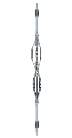
The purpose of this article, which is based on published technical papers and publicly available literature, is to inform readers of new and potential technologies in well logging and formation evaluation. It does not endorse or promote any particular technologies or service providers. Some of the technologies may be available commercially, while others may still be in the development or test phases. LOGGING DEPTHDepth measurement is fundamental to most operations associated with well construction, completion and production. Accurate depth measurements are critical in drilling and well placement, logging (wireline and LWD), formation testing, geological and geophysical evaluation, and for optimizing the completion—poor depth control can result in higher operational costs, and can lead to errors in well placement and completion that result in uneconomic wells and suboptimal field development.1, 2 Depth accuracy, quality control and management are ongoing issues that are often overlooked, or may not receive adequate attention. One suggestion to improve depth control, made in a recent paper, is the introduction of a new concept, “true along hole (TAH)” depth, which is “the true and correct position in a wellbore, determined by the length along the center of the drilled hole from a surface reference point (e.g. rotary table or kelly bushing) to the relevant reference point, typically a measuring point of the logging sonde.” TAH is obtained from drill pipe (driller’s) depth or wireline (logging) depth after applying relevant corrections. The discrepancy between driller’s depth and logging depth can be significant, and the corrections required to obtain a TAH depth from driller’s data can be an order of magnitude larger than those for wireline depths.1 LOGGING-WHILE-DRILLING (LWD)The next several sections highlight recent advancements in LWD telemetry methods. Mud-pulse telemetry. As the most widely used telemetry method deployed in LWD/MWD, mud-pulse telemetry has a low bandwidth that severely limits the amount of data that can be transmitted to surface in real time. Data reduction and/or compression techniques can increase the effective speed and data volume transmitted uphole for use in real-time applications, e.g., drilling performance and well placement (geosteering). Real-time transmission of high-quality borehole images, which are used in geosteering, is significantly impacted by the low bandwidth of mud-pulse telemetry. The compression rate determines the image resolution and must be adjusted to the detail required in the transmitted image. The loss in image quality can impact the value of the data in geosteering or other applications. Baker Hughes has developed a simulation tool for planning imaging jobs, that allows users to maximize the information transmitted in real time for a particular imaging application. The simulator uses a parameter set, based on offset-well data or simulated memory data, to model the expected real-time image and the level of detail required by the specific application. A flexible compression algorithm allows the user to optimize telemetry usage for a particular application, i.e., define compression and drilling parameters, in real time, to account for changes in geology or to permit a different image application in a particular borehole section.3 The mud-pulse signal suffers attenuation and degradation while traveling uphole to surface, and this affects data transmission in deep and ultra-deep wells. By studying and accounting for the various elements that influence the mud-pulse signal, Schlumberger has developed the next-generation MWD data transmission platform (DigiScope). This service, which can offer six times improvment on MWD transmission data rates, up to 36 bit/sec, complements the latest data-compression platform (Orion II), which has increased the effective transmission speeds seven-fold, up to 140 bit/sec, through development of a new modulation algorithm.4 Drilling with a treated, micronized, barite drilling fluid system can improve MWD signal strength by an order of magnitude.5 Electromagnetic telemetry. Electromagnetic telemetry (EMT) uses a downhole transmitter in the BHA to generate electromagnetic waves that carry encoded drilling and logging data to the surface through the intervening rock formations. EMT offers a real-time alternative to mud-pulse telemetry that is widely used in onshore wells and in underbalanced drilling, where the use of compressible fluids precludes the use of mud-pulse telemetry (see World Oil June 2011, p. 85). EMT allows direct two-way communication between the BHA and surface. EMT typically achieves data rates similar to mud-pulse telemetry, between 6 and 15 bit/sec, depending on formation resistivities and transmission frequencies. Although EMT is not restricted to specific types of borehole fluids, the signal attenuation can limit the operational range and effectiveness, particularly with depth, and formation resistivities that limit signal Weatherford has introduced a wired downhole casing antenna (EM CasingLink), designed to extend the operational depth range of its conventional electromagnetic telemetry service by significantly boosting the downhole signal i.e., improving the signal-to-noise ratio. A typical installation consists of an insulated, 0.5-in., coaxial electrical cable, run along the outside of casing and terminated onto a joint of intermediate casing at a predefined depth. The downhole antenna directly induces a signal in the receiving equipment, which decodes the EM signal. There are two types of antenna deployments: anchor wells and satellite wells. The well in which the antenna is deployed serves as the anchor, and a satellite well is an offset that can take advantage of the downhole hardware in an anchor well, such as those drilled on a multi-well drill pad. In addition to increasing the depth range for EMT, the downhole antenna allows the EMT system to bypass highly resistive or attenuating formations that adversely affect conventional EMT systems. Geophysical and offset logging data are used to determine the best depth location for the antenna.6, 7 Acoustic telemetry uses the drill pipe to transmit drilling and logging data to surface (see World Oil March 2002, p. 63, and see World Oil March 2006, p. 69), and offers an alternative to conventional mud-pulse and EMT systems in high-noise drilling environments, independent of fluid type, fluid flow or water depth. Acoustic telemetry is particularly suited for use in wells where an incompressible drilling fluid is not used—e.g. air drilling—and in offshore use, where EMT is unsuitable. After extensive field testing (see World Oil March 2008, p. 89), a new system designed for use with drilling systems has been commercialized. To date, this telemetry system (XACT AT) has proved reliable and robust in a wide range of drilling environments, where it enables faster operational decision-making, reducing drilling risk and increasing drilling efficiency.8, 9 The XACT AT network uses multiple openhole, collar-based repeater nodes to achieve effective transmission rates of 30 bit/sec at any depth. The network comprises an acoustic transmitter tool (repeaters, Fig. 1), isolator, phase tuner and receiver. The repeater nodes, are spaced at predetermined locations within the drillstring, to provide optimum signal strength and transmission speed, depending upon the angle of the borehole—typically 5,000 ft to 6,000 ft in low-angle borehole sections, and 2,000 ft to 3,000 ft in high-angle and horizontal borehole intervals. Each tool repeats the acoustic signal from the tool below, and each tool can be configured to acquire different real-time measurements along the drillstring at preprogrammed time intervals while drilling. Data transmission time to surface can vary between 10 sec and 40 sec, depending on well depth, profile and the number of tools deployed. At surface, the acoustic data are decoded, using a small accelerometer package, and then transferred wirelessly to a computer at the wellsite.
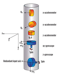
Wired pipe. BP reported on its experiences using the NOV Intelliserv wired-pipe system in a range of borehole environments. They found that the high data transmission provided by the current system (57 kbit/sec), which offers memory-quality data in real time, offered significant advantages in operations related to wellbore stability, wellbore placement (relative to the formation), hole cleaning, shock and vibration management, drilling optimization, annular pressure monitoring, downhole tool control, LWD formation pressure testing, and downhole tool reliability. One of the primary drawbacks limiting more widespread use is the lack of tools specifically designed for use with this system.10 The capability for high-speed bi-directional data transfer can: a) reduce operational risk by enabling more rapid updating of earth models, improving drilling efficiency through improved real-time monitoring of tool condition and performance, and more rapid response to well-placement decisions; and b) improve project economics through reduced NPT.11 A second-generation system capable of transmitting at rates up to 2 Mbit/sec (see World Oil June 2011, p. 85) has undergone field-testing. During the test, the network achieved a maximum data rate of 240 kbit/sec from a 200-ft BHA of 12 tools.12 Wellbore survey accuracy. Gyrodata has introduced a new three-axis gyro-while-drilling (GWD) survey tool that can operate at any attitude during the drilling process. Two-axis tool systems provide accurate estimates of azimuth in near-vertical wellbores, but the accuracy of these estimates decreases as wellbore inclination increases. Three-axis tools can measure the full horizontal earth rate signal in all wellbore geometries, and are well-suited for applications, such as high-inclination kickoffs, infill drilling and relief wells. The new tool employs three mutually orthogonal, single-axis linear accelerometers, and two new purpose-designed, highly sensitive, dual-axis rate gyroscopes, Fig. 2. The three accelerometers provide measurements of the specific force, due to gravity along their respective axes, which are used to derive inclination and high-side toolface angles. The two gyroscopes, which are mounted perpendicular to each other, provide measurements of turn rate in all three axes that are used to calculate true azimuth, and a redundant measurement provides quality control. The GWD tool is run centralized in a collar, can be placed anywhere in the BHA, and can be run in conjunction with LWD and RSS tools. Borehole inclination, azimuth, high-side gyro toolface angle and quality control data are transmitted to surface in real time, via the host LWD/MWD telemetry system. A memory multi-shot capability can provide reliable, highly accurate well surveys from TD to surface while tripping out of the hole.13
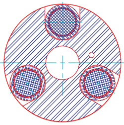
LWD NMR. Halliburton introduced a slimhole while-drilling NMR tool (MRIL-WD 4). The 4.75-in. tool is designed for borehole sizes ranging in diameter from 5.875 in. to 6.25 in. The low-field tool measures T1 while drilling—the maximum logging speed is 75 ft/hr—and T1 or T2 while wiping or sliding. The diameter of investigation is 8.5 in., axial resolution is 4 ft while logging, or 1.8 in. in stationary mode, and vertical resolution is 23 in., with new processing. The slimhole NMR tool has maximum temperature and pressure ratings of 302°F and 20,000 psi, respectively.14 Azimuthal spectral gamma ray. Weatherford’s new azimuthal spectral gamma-ray sensor (SpectralWave) provides KUTh measurements, as well as total gamma ray, in real-time and memory mode. In addition to conventional geosteering applications in unconventional reservoirs, these measurements can also enhance identification of sweet spots by enabling advanced clay typing for estimation of reservoir brittleness (used in stimulation design), and for quantitative determination of total organic carbon (TOC), using uranium content as a proxy for TOC.15, 16, 17 The new tool, which is based on an earlier design, has large (1.5 x 8 in.) gain-stabilized NaI scintillation detectors mounted on the outside perimeter of the drill collar, Fig. 3.18 This design minimizes the attenuating effect of the drill collar on the gamma-ray signal, thereby increasing the total gamma-ray count and statistical precision of the measurement.
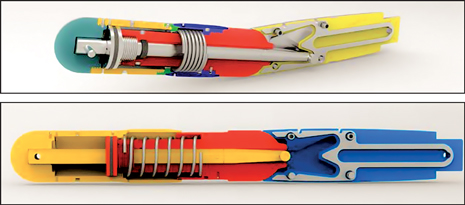
The 6.75-in.-diameter tool uses three detectors, spaced 120° apart around the tool circumference, while the smaller 4.75-in. tool has a single detector. Magnetometers track the azimuthal position of the detectors as the tool rotates and bin the spectral data into four quadrants, and the total gamma ray into 16 bins, for real-time and recorded borehole imaging. The enhanced count rates and statistical precision allow faster logging speeds, provide wireline-quality logs, and result in higher-quality borehole images that allow more accurate geosteering, improved bedding plane identification and dip determination. The vertical resolution of both tools is 12 in.19 Formation tester. Weatherford has reported on field tests of its new family of formation-pressure testers (PressureWave).20, 21 These tools provide direct, real-time measurement of formation pressure, which can be made with pumps on or off. Key test parameters per station can be transmitted at the end of the test sequence. With pumps on, one pressure measurement can be transmitted every 4 sec with 0.5-psi resolution. A communications downlink allows modification of test parameters, e.g., drawdown, station time and pad setting force, between stations. The tool is available in three sizes, 4.75 in., 6.75 in. and 8.25 in., for borehole diameters of 6 in. to 6.25 in., 8.5 in. to 10.25 in., and 12.25 in. to 15 in., respectively. The tools are rated to 302°F and 20,000 psi. High-pressure, high-temperature versions of tools are available—the 8.25-in. tool is rated to 25,000 psi, and the 4.75-in. and 6.75-in. tools are both rated to 30,000 psi. All three tools have temperature ratings of 329°F.22 WIRELINE—OPENHOLELogging cable. The premature breakage of logging cable in high-tension operations, e.g., deepwater, extended-reach and complex-trajectory wells, can result in very time-consuming and costly fishing jobs. Schlumberger has introduced a new composite logging cable (TuffLINE 18000) that has a crush-proof core design and uses high-temperature polymer technology to lock the cable armors to the core.23 This keeps the cable in a mechanically rigid, torque-balanced state. The high strength (27,000 lbf ends-free breaking strength) of this 0.5-in. cable allows safe instantaneous pulls of up to 18,000 lbf, without the use of a tension-relief system (capstan). This can reduce the risk of sticking, and also enables the use of longer, heavier tool strings for fewer, more efficient logging runs. The cable is rated for sustained operating temperatures up to 450°F.23 Tool conveyance. Prototypes of a new wireline logging bottom nose assembly, designed to enable conveyance of wireline logging toolstrings through highly rugose sections of the borehole, as can be found in Qatar’s North field, has undergone field tests.24 When the toolstring contacts a ledge, a telescoping and retracting feature (telebender) is activated, and the retraction is used to tilt and/or rotate the tool away from the ledge, Fig. 4.25 This design can reduce, or eliminate, the need for pipe-conveyed logging operations in wells with difficult geometries.
Multi-frequency triaxial array induction tool. Halliburton introduced a multi-frequency version of its triaxial array induction tool (Xaminer), which uses multiple frequencies and arrays to measure the full resistivity-tensor data in vertical or deviated wells drilled with oil-based mud (OBM), or in air-filled wells. The tool has collocated triaxial and orthogonal coils (transmitter triad), and six sets of receiver coils. The tool operates at multiple frequencies in the range of 12 kHz to 84 kHz by sequentially energizing each of the coils (X, Y and Z directions) in the transmitter triad, and measuring the signals in each of the receiver coils. The tool operates simultaneously as a conventional array induction and as triaxial induction tool. New data-processing software includes a fast algorithm that can accurately determine formation horizontal resistivity (Rh), vertical resistivity (Rv), dip and strike/azimuth, bed boundaries, three sets of conventional induction logs, and invasion parameters. The 3.875-in. diameter tool is designed for use in borehole sizes ranging from 4.75 in. to 20 in., and is rated to 300°F and 20,000 psi. The tool can be run at conventional logging speeds (3,600 ft/hr), centralized at the bottom of the toolstring, and in conjunction with tools that have a directional package.26 NMR logging. A slimhole low-field NMR logging sensor is being developed by Aachen University (Germany) to allow rapid in-situ measurement of soil moisture in the shallow vadose zone, to assist in soil management.27 Because the vadose zone is relatively shallow in most locations (< 100 m), temperatures and pressures are at near-surface levels. These reduced conditions allow logging tool designs that are substantially smaller than oilfield tool designs, and which can also take advantage stronger, but temperature-sensitive, magnetic materials. The current prototype has a penetration depth of 2 cm and has been optimized to maximize SNR.28 Schlumberger reported on two new NMR sensors that have both laboratory and logging applications. The first is an ultra-broadband, low-frequency (0.1 MHz to 3 MHz) MR probe that operates without using conventional resonant circuits for either transmission or reception. This design addresses the challenges of low-field NMR, while, at the same time, simplifying the probe circuit and allowing robust operation without probe tuning. Some of the stated benefits include programmability, flexibility, and robustness and ease of use.29 The second sensor, also a low-field apparatus, provides a very high SNR, while operating at very high temperatures and pressures. The SNR of the new sensor is 15 times that of existing commercial systems, and this allows data acquisition rates more than 200 times faster than previously possible.30 Borehole imaging. Inherent in the designs of the current wireline microelectrical imaging devices, which typically have measurement pads on four or six arms, only a portion of the borehole circumference (up to 80% in an 8-in. borehole) is directly imaged by the sensors. Since the 1986 introduction of Schlumberger’s original FMS tool, which had imaging pads on only two arms, logging service companies have sought to increase borehole coverage through the addition of more arms, more measurement pads, or through extrapolation software to fill in the gaps in coverage. The latest entries include a new tool and new extrapolation software. Schlumberger has introduced a new high-definition nonconductive-mud geological imager (NGI) for use in wells drilled with oil-based mud. The new tool employs 192 sensors on eight arms to provide 98% borehole coverage in an 8-in. well, Fig. 5.31 The image quality obtained with previous OBM tools was typically inferior to that obtained from WBM tools, because these OBM tools employed fewer sensors, and their size was increased to accommodate the specialized physics needed for the measurement. In contrast, the individual sensors (microelectrodes) on the new tool are actually smaller than those used on WBM imaging devices, and provide high spatial resolution. The operating range of the tool is 0.2 Ω.m to 20,000 Ω.m, and the tool is rated to 350°F and 25,000 psi—a high-pressure version is rated to 30,000 psi. The tool is designed for both downlogging and uplogging in boreholes with diameters from 7.5 in. to 17 in.32
Weatherford released new imaging-processing software (Reveal 360) designed to reconstruct the missing data in the non-measured gaps in borehole coverage, using morphological component analysis.33 Wireline formation testers. Weatherford has introduced a new reservoir evaluation system (RES) that can perform faster mini-frac tests. The 4.5-in. tool can be deployed with straddle packers or a high-articulation probe pad. The pad conforms to borehole irregularities to enable accurate pressure readings up to 8,000 psi. The tool employs dual high-caliber quartz pressure gauges, and a larger pump that operates at a rate of 0.7 gal/min. A new optical fluid analyzer (Reservoir Fluid Analyzer) has recently been designed and tested.34,35 Baker Hughes commercialized its latest downhole fluid characterization and testing service (RCX Sentinel), which is based on the existing Reservoir Characterization eXplorer (RCX) platform. This service is designed for pressure and fluid sampling in HPHT reservoirs, and features a focused sampling probe. In focused sampling, the probe module employs a packer with two circular fluid inlets arranged concentrically around a common center. When the packer is extended against the formation, fluids are drawn separately into each of the inlets, and maintained separately inside the tool string via two independent flowlines and pumpout modules. The separate perimeter inlet acts as a barrier to the migration of mud filtrate toward the central inlet. Independent control of separate fluid pumps connected to each inlet provides an optimum rate of fluid intake into each inlet. Sample focusing reduces the time on-station and obtains clean formation-fluid samples. A multi-tank carrier can convey between 28 and 52 sample chambers in a single run, and allows for uninterrupted sampling, thereby reducing the risk of contaminants entering the flow area. The titanium construction of the sample chambers ensures integrity in H2S environments, even at low concentrations. The ability to open and close tanks “on the fly,” (i.e., quickly and without interruption to the sampling process) ensures that the pure fluid flow reaches the single-phase tank without contamination. The service provides accurate pressure readings, even in extreme overbalance conditions. Fluid identification is achieved with a variety of optical, density, viscosity and fluorescence sensors. The 4.75-in.-OD tool (5.36 in. at the probe) is designed for use in borehole sizes ranging from 5.875 in. to 17 in., and is rated to 375°F and 25,000 psi.36 Downhole fluid analysis. The optical fluid analyzers used in many of the current generation of wireline formation testers separate broadband light into its constituent wavelengths via filters or grating spectrometers. However, these devices typically, use only a few narrow-wavelength constituents and are generally band-limited—i.e., only a small fraction of spectral data is used. However, the complex hydrocarbon fluids found in many reservoirs, particularly in some deepwater reservoirs, have many chemical constituents and are optically active over a wide range of optical wavelengths, over a broad spectral range. Halliburton’s new fluid-analysis technology (ICE Core), designed for use with the RDT wireline formation testing and sampling service, is a downhole optical-sensor platform based on multivariate optical computing (MOC) technology.37, 38 MOC combines chemometrics and pattern recognition with optical computing. Each integrated computational element (ICE) comprises optical sensing and computation—i.e., a multilayer optical element encoded with predesigned information, specific to a particular chemical constituent, such as methane, ethane, propane, saturates, aromatics or water. A multivariate optical computer may consist of many different ICE sensors designed to detect different chemical constituents or properties. As reservoir fluids are pumped through a downhole fluid sampler, light is transmitted through those fluids and sequentially through a series of ICE sensors that rotate past the light source, Fig. 6. Each sensor is programmed to recognize the chemical nature, or “optical fingerprint,” of a specific fluid component. Measuring the intensity of light passing through a sensor indicates the presence and proportion of a chemical component within the overall fluid.
The wide bandwidth response (400 nm to 5,000 nm) and high spectral resolution (16 cm-1) of these optical elements enables downhole, laboratory-grade optical analyses, while their intrinsic simplicity, small size, passive nature and high SNR offer high reliability. Multiple zones can be analyzed downhole, providing real-time lab results regarding fluid stratification in the reservoir. The answer product is calculated in situ, automatically, and in real time, thereby enabling key decisions to be made. This information serves as a valuable backup, in case physical samples became lost or damaged, and allows the operator to make decisions with a higher degree of confidence. The current tool configuration (ICS20) is able to accept up to 20 sensors. Sensors for detection of CO2, asphaltenes, water and water chemistry, resins, and H2S are under development. REFERENCES
|
- Applying ultra-deep LWD resistivity technology successfully in a SAGD operation (May 2019)
- Adoption of wireless intelligent completions advances (May 2019)
- Majors double down as takeaway crunch eases (April 2019)
- What’s new in well logging and formation evaluation (April 2019)
- Qualification of a 20,000-psi subsea BOP: A collaborative approach (February 2019)
- ConocoPhillips’ Greg Leveille sees rapid trajectory of technical advancement continuing (February 2019)

