Improving well control via drilling margin identification, influx analysis and direct measurement
Well control events are almost exclusively detected by surface measurements. Early kick detection, especially in deepwater, where the riser comprises a substantial section of the wellbore, is paramount for limiting the severity of a wellbore influx; it also improves the operator’s ability to regain well control.
|
While downhole data are presently available from tools near the bit, available data rates are sparse. The wireless telemetry bandwidth is limited, and wellbore measurements have to compete with the transmission of other subsurface data. However, a high-bandwidth, downhole data transmission system, such as a wired or networked drillstring system, has the unique ability to acquire real-time pressure measurement, at a number of locations along the drillstring. This article describes four processes to improve well control, for deepwater operations, through the use of downhole data, independent from surface measurements. First, a drillstring provides efficient kick detection and identification of ballooning zones. Gas inside the riser is also detected, and decision support is offered to personnel forced to choose between using the mud-gas separator or diverter. Second, a methodology is proposed, which uses direct measurement of real-time downhole pressure to maintain constant BHP during well kills in deep water. Third, downhole surge and swab pressures are available through a measurement-while-tripping system. Fourth, well-control barriers are verified using downhole information, independent of data from the surface. All of these workflows allow for higher levels of automation, supporting wellsite personnel and improving the safety of operations. This article presents examples of field data that illustrate these cases. DEEPWATER WELL CONTROLDeepwater operations call for new processes and technologies, to ensure the safety of workers, the environment and assets. Against this backdrop, the following observations are offered:
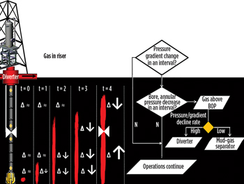
This article considers a number of processes and technologies that are relevant to these observations. Supplementing surface data with downhole information. A wired drillstring provides high-speed—57,600 bytes per second (bps)—data transfer, from downhole measurement tools.1 This telemetry capability is magnitudes faster than current, state-of-the-art, wireless data transmission systems, which are only capable of transmitting dozens of bps. Further, the data transfer rate is maintained with increasing depth, and communication with downhole tools is provided through a two-way communication capability. Finally, data can be acquired at each of the network nodes along the drillstring. High-definition downhole information—even in the absence of flow—is now available during all well construction phases, through battery-powered tools. The high-speed downhole information, obtained via the drillstring, and the along-string evaluation, supplements existing surface data; this combination improves well control and integrity. Kick detection and gas-in-riser identification. Prompt kick detection is critical in deepwater operations, with a subsea BOP stack, as it is imperative that the rig crew detect the influx before the hydrocarbons rise above the stack. If the kick is not detected, and the hydrocarbons are allowed to rise above the BOP, the well control response options are severely limited, and the risk of a blowout increases significantly. This risk is especially acute in deepwater situations, where the riser comprises a substantial section of the wellbore, and productive hydrocarbon zones can be found at relatively shallow depths below the mud line. In such situations, early kick detection is vital, to both limit the severity of a wellbore influx and improve the operator’s ability to regain well control.2 While response times for early kick detection are crucial, wellsite and operational personnel traditionally have relied on surface measurements, such as flow in and out, pumping pressures, and a number of mechanical measures, to identify a wellbore influx. An increase in the “closed-loop” mud circulation system, a standpipe pressure decrease, or changes in a variety of drilling parameters, are all indicators of a kick. Gas influxes in an oil-base fluid environment may remain soluble, and avoid detection, until the point where they break out of solution at shallower depths near, or even above, the BOPs. Environmental conditions, such as rig heave, roll and pitch, may also delay early kick detection. Figure 1 shows a well influx occurring at the bit while drilling; it also depicts a decision flowchart using the absolute pressure readings and pressure gradients between the along-string pressure measurements. At initial conditions (time(t)=0), the incoming formation fluids are located below the pressure sensors; therefore, the absolute pressures and gradients remain unchanged. As drilling goes on, and the formation pressure continues to exceed the hydrostatic (dynamically exerted) pressure, the formation fluids continue to enter the wellbore (t=1). The pressure sensor nearest to the bit, sensor 1, is the first to record an annular pressure reduction. As the influx height increases to the next sensor, sensor 2, the corresponding pressure gradient is reduced, between the two deepest sensors that are nearest to the bit, while the gradients in the sections uphole remain unchanged. At times t=2 and t=3, as the wellbore influx passes sensor 3 and sensor 4, the gradients in these subsequent sections also decrease. At t=4, the BOPs are closed, and the pressure below the rams or annular increases. The pressure and pressure gradients continue to drop, for the sensors inside the marine riser. For a high-pressure decline, the system advises to divert flow overboard; the mud-gas separator can be lined up for lower pressure declines.
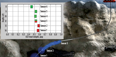
The location, and type, of the influx can be determined through independent pressure measurements from surface measurements.3 Once the influx is identified, maintaining and controlling BHP is facilitated by direct downhole measurements, as opposed to a complex computation performed under stress. The network’s ability to take multiple, distributed pressure measurements, along the entire length of the drillstring, allows developing well control issues to be analyzed and characterized accurately. The downhole data, independent from surface data, are available at stationary conditions, when the pumps are off, as well as when the pumps are on. It also improves safety; corrective actions can be taken while the event is limited in size and, therefore, more easily managed. Figure 2 shows an example of a fluid traveling up the annulus. In this instance, a pressure increase is recorded by the bottom two pressure sensors. As time advances, the sensors farther up the wellbore will identify the pressure increase.
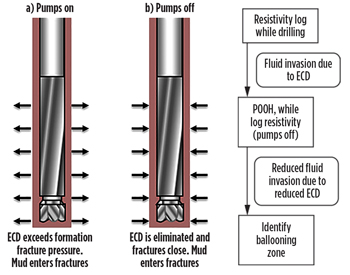
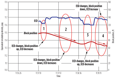
Distinguishing ballooning from a kick. Ballooning, which is also known as wellbore breathing, occurs while drilling (naturally) fractured formations; it is often interpreted mistakenly as a formation influx. The ballooning mechanism originates from fracture deformation, producing drilling fluid loss and gain, as fractures open and close. The fracture opening is caused by an increase of equivalent circulating density (ECD) during periods of flow, resulting from the fluid-flow friction in the annulus. With pumps off, the ECD is reduced to static mud weight, closing the fracture, and drilling fluid gains are observed, Fig. 3.
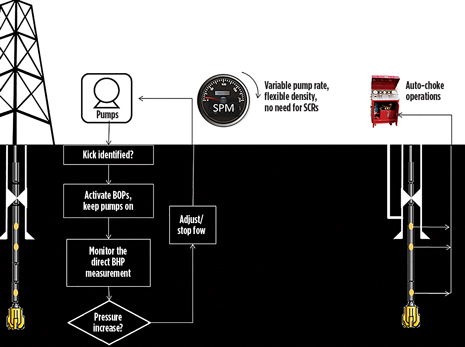
Wellsite personnel are trained to monitor for fluid gains, as these are indicators of a wellbore influx. However, there are distinct differences between a kick and ballooning. First, in the case of a kick, the fluid gain rate will increase over time; the rate decreases for ballooning. Second, in the event of balloning, the shut-in pressure cannot exceed the ECD value. However, in the event of a kick, the shut-in pressure is limitless. To distinguish a kick from ballooning, one typically relies on surface measurements, as there is, currently, no reliable, downhole fluid-flow measurement available. Establishing the shut-in pressure is not operationally feasible; it would wear-out subsurface BOP elements unreasonably. Logging while drilling (LWD), downhole resistivity propagation logs can identify fluids, which have invaded fractures or micro fractures. The methodology used to acquire and compare resistivity propagation logs (see flow diagram in Fig. 3) aids in identifying the zone responsible for the ballooning, and uniquely utilizes the network drillstring’s ability to acquire high-definition log data, in the absence of flow. An algorithm is utilized to quantify the likelihood that wellbore sections are causing the ballooning. Well control with direct measurement. Direct measurement of BHP, the pressure nearby the casing shoe, and pressure at discrete points in-between, offers unique benefits compared to the two widely used constant BHP circulating methods. First, with the aid of direct measurements, drillers can activate the BOPs without stopping the pump. Instead, flowrate can only be reduced, and ultimately paused, as guided by the directly measured downhole pressure readings in the minute that it takes for the annular preventer to physically close. Second, circulation can commence as soon as surface equipment is lined up, similar to the driller’s method. One distinction, however, is that kill mud can be introduced once it becomes available, instead of after completing a full circulation, as required by the driller’s method. This reduces the risk associated with periods that do not have circulation. Third, kill mud can be circulated at the density that it becomes available by mixing; a homogenous mud weight isn’t required, as is with the wait-and-weight method. The swifter introduction of heavier mud, and the quicker circulation of the influx, reduces the maximum pressure at the shoe and BOP. Fourth, the kill rate is optimized, benefiting from direct pressure readings near the casing shoe (or alternatively the weakest known formation zone). The kill rate is, therefore, not necessarily constant. This means that the rate may increase as the kill advances and is not automatically equal to an earlier established, slow-circulating-rate (SCR), a measurement that is obsolete in deploying this method. Finally, a large difference compared to the wait-and-weight method—also known as the engineer’s method—is that no calculations are required, since a direct measurement drives the operation of the (automatic) choke for the required back pressure, Fig. 4.
The direct-measurement method improves the ability, and ease, of kick management. It also improves analysis of fluid-gas swapping, as is occurring with gas migrating toward surface. Further, the direct measurement ability helps identify gas breaking out of solution, including the ability to track its expansion through pressure gradients, along the drillstring. The implication, during well control, may be a drastic altering of fluid friction, as the gas breaks out of solution, within the reduced ID of the chokeline. This sudden change in friction could significantly impact the BHP, as it would go unnoticed by surveillance of just surface measurements at the choke. The high-frequency, downhole pressure measurements can, however, convey these pressure fluctuations to enable closed-loop control of the choke, aiding wellsite personnel during challenging and non-routine operations, with higher levels of automation. Well control during tripping. Tripping is the leading operation that results in well control events (Table 1). Swabbing is caused by friction effects, and volumetric changes, as the drillstring is hoisted, Fig. 5. Historically, detection of an influx relied on surface measurements. To prevent swabbing, drillers rely on conservative rules of thumb, or empirical models, to determine the safe operating ranges for the trip speed. Excessive surge pressure could result in time-consuming lost circulation events, while excessive swab pressure could lead to hazardous, and costly, well control events.
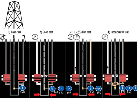
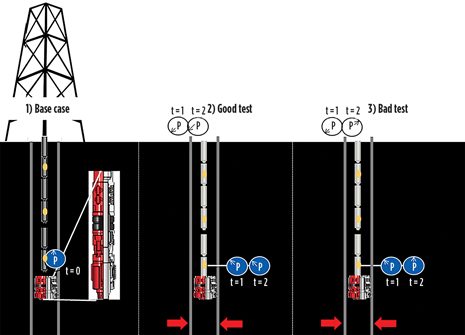
Through the drillstring, wellsite personnel could obtain insight into dynamic downhole hydrostatic pressures with real-time measurements while tripping, by either connecting to the networked drillstring, while suspended in the rotary table during connections, or while being hoisted in the elevators. Measurements while tripping (MWT) can accurately reveal the dynamic surge and swap pressures, which have not been available in real time without connecting the top drive. Because the broadband network integrates the downhole measurements with the surface equipment, the industry now has a truly closed-loop feedback system within its reach. The real-time downhole pressure measurements allow the drawworks system to set the optimum tripping speed. Verify well control barriers. Regulations call for negative pressure testing of wells, where the wellbore will be exposed to negative pressure conditions (for example, when the BOP and riser are disconnected from the wellhead during permanent or temporary abandonment procedures). Today’s procedures, and the resulting interpretations of negative pressure tests, rely on surface measurements for verification of wellbore integrity. Adding complexity to the already limited data stream during the test is the possibility for heterogeneous fluid density columns in the annulus, and the chance for plugged choke and kill lines or a misaligned surface valve. Downhole information, independent of surface measurements, can help analyze the pressure buildup that may follow once the drillstring is displaced with a lighter fluid (typically base oil or water) following stinging into a downhole circulating packer. Alternatively, the pressure build-up can be monitored downhole, once the choke and/or kill line has been displaced with lighter fluid, and the BOPs have been closed, Figs. 6 and 7. In both methods, the bore and annular pressure measurements, at the various measurement stations along the string, are independent from surface measurements. These complement one another and help to discriminate from false negatives.
CONCLUSIONSDeepwater operations call for new processes and technologies, to ensure the safety of workers, the environment and assets. Independently acquired downhole information could improve detection, analysis and control—even in an automated fashion—when a kick is taken. Decision support is offered, about whether to line up the diverter or mud-gas separator, in the event that gas enters the riser and migrates above the BOPs. The drillstring can also offer downhole information to identify the zone responsible for ballooning, a phenomenon that, as previously mentioned, has the potential to be mistaken for a kick. Well control efficiency is improved through direct time savings and a lower maximum pressure experienced at the shoe through the direct measurement method. The automation of trip speeds impacts the well control events experienced during tripping. Finally, the verification of well-control barriers, for well integrity, during all well construction phases with negative pressure testing. The offered processes and technologies enable automation to support humans in the decision-making process, even with emergency shutdown decisions. This type of support is vital, given the industry’s challenging shortage of proven, competent people. RECOMMENDATIONSThe described workflows depend on the availability of fast downhole telemetry and accurate measurements along the drillstring. It is recommended to acquire the temperature measurements directly from the annulus and bore, instead of measuring temperature from electronic boards that are embedded in the tool housing. Pressure measurement accurancy must also be improved further, and early results indicate that the new generations of digital sensors even have the sensitivity to identify the location of loss zones. ACKNOWLEDGEMENTS The author wishes to thank the management, operations teams and wellsite crews of National Oilwell Varco. The author also would like to thank NOV’s service partners for their contribution and support in publishing this article. REFERENCES
|
|||||||||||||||||||||||||||||||||||
- Applying ultra-deep LWD resistivity technology successfully in a SAGD operation (May 2019)
- Adoption of wireless intelligent completions advances (May 2019)
- Majors double down as takeaway crunch eases (April 2019)
- What’s new in well logging and formation evaluation (April 2019)
- Qualification of a 20,000-psi subsea BOP: A collaborative approach (February 2019)
- ConocoPhillips’ Greg Leveille sees rapid trajectory of technical advancement continuing (February 2019)

