|
A deepwater, extended reach well for a major operator in West Africa required a tangent section in a soft formation, maintaining an 85° drift angle for about 11,150 ft in a single interval. The production section required steering the well into the best section of the pay zone. To accomplish the drilling objectives, an exhaustive, detailed plan with multiple scenarios was required before the well was drilled.
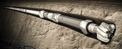
The plan included the use of a tailored bottomhole assembly (BHA), with a point-the-bit rotary steerable system (RSS), and an extended-gauge bit. The BHA had to overcome the formation’s natural tendency to drop inclination, while creating a high-quality wellbore to provide sufficient hole cleaning capacity in the deeper sections. The side force at the RSS fulcrum point can be compared with the formation’s compressive strength. If the side force is higher, the hole will enlarge. By incorporating an additional contact point in the BHA configuration, the team was able to reduce side force at the fulcrum point and limit hole enlargement. A state-of-the-art modeling tool enabled the team to balance the dynamic BHA forces while drilling, to avoid common drilling problems.
The five sections required for the deepwater extended reach well were drilled with only six BHAs. The challenging, 12¼-in. tangent interval was drilled in one run, with the modeled BHA, reaching a total length of about 11,150 ft, the longest 12¼-in section in an ERD well in the area.
BACKGROUND
West Africa has seen a significant shift in deepwater drilling activity. Typical field development plans (FDP) call for step-out directional and ERD wells to reach large areas from a single drilling platform.
A successful ERD well requires an effective drilling plan. The plan should be comprehensive, but feasible, for achieving the desired results. In this case study, the ER trajectory called for the delivery of build rates in the 17½-in. hole interval, not previously reached in the shallow soft formations, building up to an 85° sail angle. For the 12¼-in. tangent interval, the BHA must hold the angle and step-out the well along faulted shale, and later turn the well more than 60° in azimuth to properly intersect the reservoir.
A proprietary BHA planning tool was used to model and design the appropriate BHA for each interval. Different iterations were performed to account for potential hole enlargement, build-rate response, vibration mitigation and hole cleaning. The proposed solution was to use a point-the-bit RSS, with attributes to overcome hole enlargement and deliver the planned trajectory and hole quality.
The RSS was used to drill all of the directional intervals. All intervals were drilled casing-to-casing in one run, with one BHA per section. Each section was drilled effectively to deliver an average 3.5°/100 ft in the build section, while minimizing tool deflection in the 12¼-in. section. This was the longest tangent ever drilled in the area. Finally, the production interval was drilled and opened up from 8½ in. to 9½ in. to accommodate the completion. The well reached the pay zone with less than 1 m of separation from the well trajectory.
ERD ENVELOPE
In the early 1980s, a well with a horizontal displacement of 5,000 ft from the surface location was considered an ERD well, while in recent years over ~40,000-ft displacement has been achieved, Fig. 1. Gravity has a big impact on the drilling process—the shallower the well, the more complex the ERD operation. Several factors come into play, including available drilling weight, tripping into and out of the hole, fracture gradients, equivalent circulating densities, and torque and drag. The MD/TVD ratio is a measurement used to define the complexity of the ERD operation. The red circle indicates that this ERD well case history has a 2.5 MD/TVD ratio.
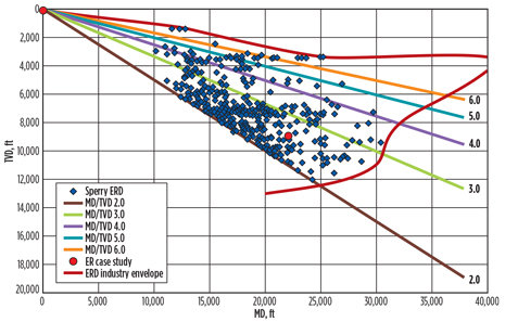 |
| Fig. 1. Industry extended reach well drilling envelope, as measured by the MD/TVD ratio. |
|
MAIN DRILLING CHALLENGES
The case study well is an oil producer, planned to reach about 22,300 ft, TD. The main objective is to drain the reserves in an unswept area of the reservoir, that cannot be reached with conventional well profiles. The plan called for building angle in the surface hole to 85° inclination and keeping the sail angle close to the top of the reservoir, then turning around 60° in azimuth and dropping to an inclination of 70°. The drilling program required the intermediate casing to be landed at the top of the reservoir in the correct azimuth to maximize pay zone exposure.
The critical well challenges included the ability to obtain sufficient, smooth build rates in a soft formation, and manage hookload, and torque and drag loads, critical to the successful step-out of the well.
To reach the pay zone, the plan called for an 85° tangent along faulted shale, then a turn of 60° in azimuth for proper reservoir intersection. This step-out in the 12¼-in. section required a perfectly tuned and balanced BHA that would be able, for the first time in the area, to drill an 11,150-ft tangent interval.
The third critical challenge was the narrow mud-weight window required to control ROP, to keep the ECD in the safe operational window.
MODELING AND PLANNING
A model–measure–optimize process, which focuses on integrated planning and execution activities, was used to achieve well objectives and improve drilling efficiency. Using specific BHA simulators, the operational conditions were defined to determine the optimum parameters required to generate optimum ROP and BHA performance. The BHAs were modeled, using an analytical steady-state planning tool that simulates complex downhole conditions (Chen, 2007).
Hole enlargement in soft formations is a factor that can significantly affect BHA performance. Modeling was performed, using different enlargement scenarios. Hole enlargement can be reduced by reducing the sideloads generated at contact points along the steering BHA. Sideloads generated at the bit by the steering system can be reduced and managed by adding contact points to the lower non-rotating housing. If hole enlargement occurs, the contact points on the lower housing will reduce the sideforce at the bit and limit the amount of hole enlargement that occurs. This modeling technique can be used to control hole enlargement, when the formation compressive strength is lower than the side force generated by the drive system.
Well trajectory corresponds to an offshore well with more than a 3,280-ft water depth, a total MD around 22,300 ft and a TVD of 8,860 ft, Fig. 2. The well has a MD/TVD ratio of 2.5.
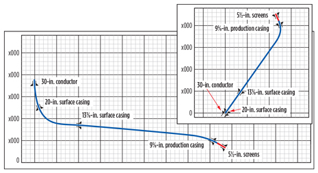 |
| Fig. 2. Extended-reach well trajectory. |
|
Tool geometry. BHA modeling for the 17½-in. section indicated a need to tune the RSS tool geometry. The side force at the fulcrum point can be compared with the formation compressive strength, if the side force is higher, the hole will enlarge. By incorporating an additional contact point in the BHA configuration, the team was able to reduce sideforce at the fulcrum point and limiting hole enlargement. An additional stabilization point was added to the conventional RSS configuration. This contact point at 4.72 ft from the bit reduced the sideload generated at the fulcrum point, with the bit sleeve at 2.23 ft. The objective was to minimize the side force generated by the drive system, which in turn, avoids hole enlargement due to the low compressive strength of the formation at this shallow depth. Fig. 3 shows the BHA modeling for the 17½-in. build section interval.
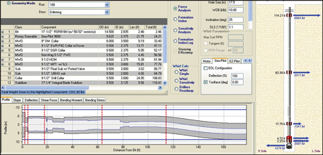 |
| Fig. 3. 17½-in. interval BHA modeling. |
|
Similar criteria were used to design the 12¼-in. BHA. However, the goal was not only to generate minimum side forces, but also to maintain angle and direction in the tangent section, with minimum deflection of the steering system. Again, a stabilization point was used on the lower non-rotating housing to reduce hole enlargement. The geometry and deflection were optimized for the tangent section to produce neutral behavior, and maintain the inclination with minimal steering. Balancing the loading on the BHA helps to reduce vibration and stress in the downhole tools, which improves performance and longevity.
PROPOSED BHAs
A sensitivity analysis, using a model calibrated with offset wells, was performed with different tool geometries and BHA components. Each BHA was modeled by varying stabilization points, stabilization diameters, component positions, percentage of deflection, etc. The analysis had two main purposes: 1) generate continuous dog legs to follow the trajectory smoothly while keeping tool deflection capability in reserve, and 2) maintain the sail angle in the 12¼-in. section with minimal tool deflection.
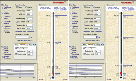
After calibrating the tool response based on offset data, the model for the 17½-in. interval showed a 3.81º/100 ft response. The calibration took into account the hole enlargement that often hampers build rate capability, and the hole size was estimated to be 17⅞ in. or a ⅜-in. overgauge hole. Fig. 4 shows the BHA response in a ⅜-in. overgauge hole.
 |
|
Fig. 4. 17½-in. calibrated BHA response, left, and 12¼-in. RSS deflection required, right.
|
|
Correspondingly, multiple simulations were performed to define the size and position of the stabilizers to drill the extended 12¼-in. tangent section. The hole was estimated at 12⅜-in. or ⅛-in. overgauge. To hold the 85° inclination, the model indicated that the RSS would require a deflection of 30%. The BHA was precisely balanced to manage the natural drop tendency of the formation, while keeping building capability in reserve, Fig. 4.
EXECUTION
During execution, the model–measure–optimize approach calls for performance measurement and optimization, based on the real-time data captured from subsurface and surface sensors. The optimization process is part of a proprietary drilling performance workflow, allowing the drilling team to use planning analysis and road maps to track the drilling process, and adjust variables when required.
Using advanced modeling tools—which include a newly developed generic algorithm—allowed the team to deliver accurate drilling models. In addition, the point-the-bit RSS used was matched with a long-gauge bit that creates an integrated drilling system, which incorporates the bit into the BHA design. The bit included correct features and steerability design for the intended application. The matched drilling system also allowed the team to accommodate different attributes and tool geometry modifications to achieve the model requirements.
BHA performance. The BHA proposed for all sections included a modified RSS configuration to overcome the challenges specific to each interval. The build section was drilled flawlessly, delivering an average of ~3.5°/100 ft (from 3.2° to 3.8°), matching the expected ~3.81°/100 ft. The 12¼-in. BHA was able to maintain the sail angle with tool deflection on the order of 35%. No problems were experienced, as the planned trajectory was followed with only a few deflection adjustments required to correct azimuth.
The production interval was drilled in the same way, using RSS with adjusted geometry to overcome the trajectory challenges experienced in a soft formation.
The tools not only performed as expected, from a BHA response point of view, but the optimized design allowed drilling of all sections, casing-to-casing, with no downtime while drilling. A further refinement in the contact points and side force of the tool design has enabled trajectory with higher dog legs (above 4°/100 ft) in the 17½-in. soft formation section, while retaining deflection in reserve. This capability has allowed the use of RSS in the shallow surface intervals offshore, typically drilled with motors.
The incorporation of RSS in big holes has yielded smooth build sections in extended reach wells. Specific benefits include reduction in the sail angle; reduction in torque and drag for faster, smoother tripping; and access to reserves farther from the same platform, Fig. 5.
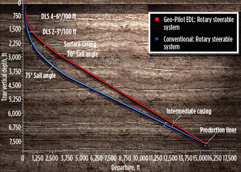 |
| Fig. 5. Benefits of high-dogleg RSS in ERD. |
|
Survey management. In extended-reach wells, survey management is fundamental, because of cumulative errors at the point of hitting a geological target. Large uncertainties severely constrain the available targets. Through better understanding of the error sources, uncertainties were reduced to ensure reaching the geological target.
SAG correction was used to account for the error in inclination measurements caused by the misalignment of the directional sensor, in relation to the borehole. MWD azimuth data were calculated, using In Field Referencing (IFR), where the values for the magnetic declination angle, dip, and field strength were adjusted for local crustal anomalies. In addition, a rigorous quality control of the raw data was performed through multi-station analysis, using proprietary software. The IFR correction was applied automatically, in real time, at the rig site, by using the values listed in the Well Survey Data Sheet. The survey management team performed QC and multi-station analysis in real time. To mitigate collision risk, surveys were taken every 30 ft during the first 600 ft, and the well was monitored from town while drilling below a separation factor of 2.0. At TD, the wellbore was positioned within 1 m of the proposed location.
Hole-cleaning management. Multiple unplanned events can be related to a narrow mud weight window and efficient hole cleaning. These challenges were addressed in the planning stage, and the drilling road map included the lower and upper limits of the mud weight window. A sensitivity analysis also was performed to determine the maximum ROP to keep the ECD within limits. An upper ROP limit of was defined early in the planning stage. During execution, a further limit was implemented, based on real-time data and live road maps.
Mud losses were experienced below the 13⅜-in. casing shoe, due to an excess of cuttings from cleaning out the rat hole. The mud weight was adjusted, and drilling resumed. The well was drilled to TD with no additional loss events. The ROP was controlled to 100 ft/hr while drilling practices were implemented to maximize hole cleaning.
A torque-and-drag road map also was used to monitor downhole drilling conditions and identify deviations from the normal trend. Figure 6 shows actual pick-up, rotating and slack-off loads during drilling of the 12¼-in. hole. Real-time monitoring allowed the team to make decisions regarding ROP, drilling parameters, and drilling practices, to ensure proper hole cleaning.
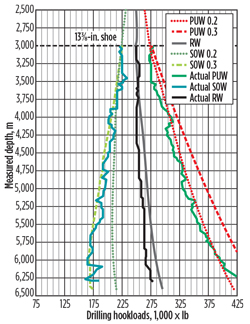 |
| Fig. 6. Real-time T&D road map. |
|
Vibration analysis. In the planning stage, the downhole conditions of the BHA were modeled to determine frequencies that could exacerbate detrimental downhole vibrations. Figure 7 shows critical RPM vs. WOB for the 12¼-in. interval. Due to the complex well trajectory, only a few places allowed a safe RPM. The yellow area was the target area, where RPM would not cause BHA resonance.
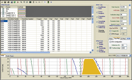 |
| Fig. 7. Dynamic BHA modeling with a safe drilling parameters window. |
|
No vibration issues were experienced in the 17½-in. build section. Standard drilling practices were applied and close monitoring of real-time vibration kept it within the green zone during the entire run. While drilling the 12¼-in. extended interval, stick-slip vibration occurred. The cause of the stick-slip vibration was the interaction of the drill pipe tool joints lying on the long, 85° tangent. A TEM (torsional efficiency monitor) sensor was used to continuously monitor stick-slip, and interactive software helped to identify the mechanism of vibration and recommend mitigation (what changes to make to the drilling parameters to keep vibration level at least in the yellow zone). The best place was between 180 to 200 rpm, and this continued until TD of the section. Figure 8 shows the downhole speed measured at the rotary steerable system while drilling 12¼-in. step-out interval. The higher frictional torque along the length of the wellbore reduces the amount of energy reaching the bit, generating drillstring torsional vibration. Drilling parameters were tuned to overcome stick-slip events and smooth the drilling process.
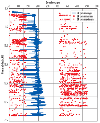 |
| Fig. 8. Downhole RPM while drilling |
|
Data from downhole sensors were monitored in real time. Vibration sensors that can identify lateral, axial and torsional vibration diagnose the correct vibration generation mechanism. Some suggested solutions are displayed to mitigate the vibrations.
Both 8½-in. and 12¼-in. sections experienced stick-slip vibration. Drilling parameters were adjusted to 200 rpm, which lowered the stick-slip vibration from severe to moderate. Even though the BHA was balanced and matched with an extended gauge bit, the vibration phenomena still occurred during the last two intervals. However, the team was able to manage the vibration levels and avoid catastrophic tool failures.
CONCLUSIONS
Despite the stick-slip dysfunction, the BHA modeling and the implementation of the model–measure–optimize process were the key for the BHA to last for 115 drilling hours until TD was reached for the 12¼-in. section.
- The critical path to execute flawless drilling was an analytical steady-state planning tool that simulated complex downhole dynamic conditions for each proposed BHA.
- Comparing modeled loads at the fulcrum BHA point to the formation compressive strength was paramount to overcoming hole enlargement in soft formations.
- The model–measure–optimize process helped in not only planning, executing and measuring performance, but also for optimizing drilling, based on real-time data captured from both the subsurface and the surface.
- BHAs used for all sections employed a modified RSS configuration to overcome the challenges specific to each interval.
- The team was able to manage the vibration levels and avoid catastrophic tool failures.

REFERENCES
- Bailey, J. R. et al, “Drilling vibration modeling and field validation,” SPE/IADC paper 112650, presented at the IADC/SPE Drilling Conference, Orlando, Fla., March 4-6, 2008.
- Chen, David C.K., “Integrated BHA modeling delivers optimal BHA design,” SPE/IADC paper 106935, presented at the Middle East Drilling Technology Conference and Exhibition, Cairo, Egypt, October 22-24, 2007.
- Dow, Michael et al, “Introduction of a modified rotary
steerable system in Papua New Guinea improves drilling performance in poor quality wellbores with tectonic breakouts," SPE paper 147809, presented at the Asia Pacific Oil and Gas Conference and Exhibition, Jakarta, Indonesia, September. 20-22. GD-GL-HAL-SD-GP400, Geo-Pilot Best Practices, revision 1.5, 2010.
- Stuart, D. et al, “New drilling technology reduces torque and drag by drilling a smooth and straight wellbore,” SPE/IADC paper 79919, presented at the SPE/IADC Drilling Conference, Amsterdam, The Netherlands, February 19-21, 2003.
ACKNOWLEDGMENT
This article is adapted from “Offshore West Africa deepwater ERD: Drilling optimization case history,” SPE paper 163485, presented at the SPE/IADC Drilling Conference and Exhibition, Amsterdam, The Netherlands, March 5-7, 2013.
|

