MOHAMMAD A. ALI and ABDULRAHMAN S. AHMARI, Saudi Aramco
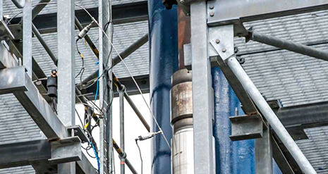 |
| Pressure sensors, 6 in. and 10 ft away from the TRSSSV, in flow test rig at GL Nobel Denton. |
|
Around the globe, there is a huge focus on developing gas from tight reservoirs and shale, where long horizontals, multi-stage fracturing and multiple zones are required to make a commercially viable well. While these developments require complex sand face completions to allow multi-stage fracturing, the upper completions for such wells are relatively simple. Most of the equipment required is readily available off the shelf. On the other hand, some recent offshore gas discoveries in the Arabian Gulf are so prolific, that production from massive single zones is limited only by the sizes of the well completions.
Two recent gas discoveries in the Arabian Gulf offered the opportunity for significant cost-savings and accelerated development, if large-bore completions could be utilized to reduce the number of wells, and cost of surface facilities required to achieve the target production rate. Saudi Aramco, having already developed a similar, adjacent, offshore HPHT gas field with a 7-in. mono-bore completion, took on the challenge of developing the new assets with 95/8-in. mono-bore completions.
TRSSSV DESIGN CONSIDERATIONS
One key consideration for this large-bore completion design was the tubing-retrievable subsurface safety valve (TRSSSV). TRSSSVs are fail-safe valves designed to shut in a well below the surface, in case of catastrophic damage to the wellhead facilities, or other completion string failures.
The TRSSSV is connected to the surface by a small-diameter (usually ¼-in. OD) high-pressure control line. While producing, the well valve is held open by applying hydraulic pressure to the valve through the control line. The control line pressure pushes against a piston compressing a spring, which, in turn, pushes open a normally closed flapper to allow the reservoir fluids to flow through. Loss of hydraulic pressure from the control line, due to a failure at the surface, allows the spring to push the piston back, thereby closing the flapper valve and shutting in production.
When selecting a TRSSSV, it is vital that upon the loss of hydraulic pressure to the control line, the TRSSSV closes, seals and continues to function, after a closure, at the highest anticipated flow velocity. While 95/8-i.n TRSSSVs have been used in high-flowrate wells since the early 1990s, the pressure rating of the valves has been limited to 5,000 psi, and they did not incorporate the self-equalizing option.1,2 The first reported use and qualification of 95/8-in., 5,000-psi-rated, non-self-equalizing valves, including a slam test at 450 MMcfgd, was conducted by RasGas Company Ltd. in 2007.3
As both of Saudi Aramco’s planned developments have reservoir pressures in the 10,000-psi range, the projects’ success depended on the development and qualification of 95/8-in., 10,000-psi TRSSSVs. Also, to achieve the full benefit of these large-bore completions and optimize the surface facilities, it was decided to incorporate a self-equalizing option.
Key considerations for the TRSSSV design in these completions were the following:
- Tubing-retrievable, self-equalizing subsurface safety valve
- 10,000-psi working pressure
- 12.2-in., maximum OD, to fit inside specially designed, 14-in. production casing
- Metal-to-metal flapper seal
- Full-bore access in 95/8-in. tubing
- Full, functional test, as per API 14A specifications
- Slam closure test at +400 MMscfd.
API 14A specifications cover testing requirements for TRSSSVs, up to 7 in. However, as 95/8-in. completions are a relatively recent development, Spec API 14A does not address the slam closure testing of 95/8-in. TRSSSVs. It was deemed necessary to design a slam closure test for the subject TRSSSV to suit Saudi Aramco’s well conditions, to ensure that it can withstand the most severe closure conditions during the life of the wells.
WELL PARAMETERS FOR SLAM TEST
Subject reservoirs are non-associated, expansion drive, dry gas reservoirs, with no condensate and minimal water production. Development wells are planned to maintain a plateau production of 300 MMcfgd/well for more than 15 years, but the wells may be required to produce as high as 400 MMcfgd during high-demand summer seasons. Accordingly, the completions, including the TRSSSV, have been designed for an expected life of 15+ years.
Well completions in expansion drive gas reservoirs have to be designed for high initial reservoir pressure, at which gas velocities are low, but at the same time have to withstand the final, much-higher gas velocity at a reduced reservoir pressure. Ideally, a slam closure test at both extreme conditions should be conducted, to simulate the worst-case pressure and flow velocity conditions. However, as described below, none of the test facilities currently available are equipped to simulate such extreme flowrates, velocities and pressures in the required combination. Therefore, slam tests were designed, to utilize the test facilities, to simulate well conditions as closely as possible.
TRSSSV GAS SLAM TEST FACILITIES
More than one firm and location were utilized, to conduct the slam tests. What follows are the procedures and results from these tests.
Southwest Research Institute (SwRI). Founded in 1947, the Southwest Research Institute (SwRI), is one of the oldest, and largest, independent, non-profit, applied research and development (R&D) organizations in the U.S. The institute’s headquarters occupy more than 2 million sq ft of office and laboratory space, on more than 1,200 acres in San Antonio. The institute consists of 11 technical divisions that offer multi-disciplinary, problem-solving services in a variety of areas in engineering and the physical sciences.
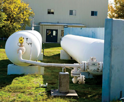 |
| Fig. 1. High-pressure nitrogen tanks at SwRI’s flow component testing facility. |
|
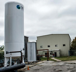 |
| Fig. 2. Cryogenic nitrogen storage tank and convertor at SwRI’s flow component testing facility. |
|
Flow component testing facilities at SwRI uses two high-pressure Nitrogen Tanks (Fig. 1), with a total volume of 1,125 ft3. The tanks are charged to a maximum pressure of 3,000 psi, using cryogenic nitrogen from a storage tank and a high-pressure Nitrogen pump/convertor, Fig. 2. The TRSSSV is rigged up vertically in a flow test rig (Fig. 3), such that nitrogen from the two high-pressure tanks flows from the bottom of the valve and is vented, to air, from the top, Fig. 4. The valve operates remotely through a ¼-in. control line, similar to the one used in the actual well completion.
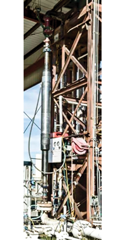 |
| Fig. 3. TRSSSV installed in the flow test fixture at SwRI’s flow component testing facility. |
|
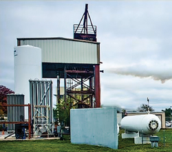 |
| Fig. 4. Nitrogen flowing through TRSSSV at SwRI’s flow component testing facility. |
|
The TRSSSV is cycled open and closed by applying hydraulic pressure to the control line at ambient pressure and temperature, to establish pre-slam operating parameters. The valve is then held open by applying hydraulic pressure, and nitrogen is allowed to flow through the valve. Once the desired flowrate is established through the TRSSSV, hydraulic pressure is vented quickly, to slam shut the valve under flowing conditions. The whole process is monitored and recorded, using various pressure and flow sensors, Fig. 5. The valve is then removed from the flow loop and pressure-tested to the maximum working pressure, using nitrogen in a high-pressure test chamber, Fig. 6. Once the pressure test is complete, the valve is cycled open/closed and drifted.
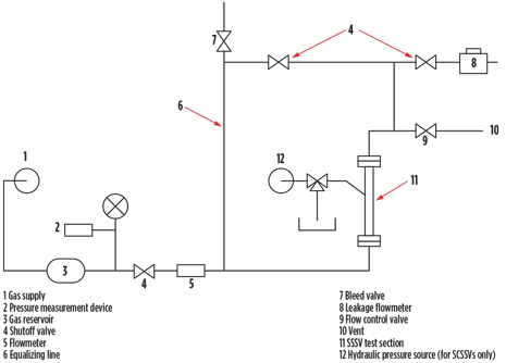 |
| Fig. 5.TRSSSV slam closure test flow schematic at SwRI’s flow component testing facility. |
|
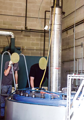 |
| Fig. 6. TRSSSV being lowered in high-pressure test chamber after slam test at SwRI. |
|
SwRI Flow Component Testing Facilities conform closely to Spec API 14A flow test requirements. Yet, due to the limited amount of nitrogen volume available from the two tanks, the flowrates and velocities required for the 95/8-in. TRSSSV could not be achieved. As the flow is initiated through the valve, the nitrogen pressure starts to deplete quickly and, within a few seconds of achieving the maximum flowrate, it starts to drop. Valve closing has to be initiated within 2 to 5 sec of starting the flow, and there is little control over the flowrate, velocity and pressure, at which the valve actually slams. Various attempts may have to be made to achieve the maximum flowrate and velocity at the slam.
Once the slam test is complete, the facility is well-equipped to quickly remove the valve from the test fixture, and pressure-test it with nitrogen, cycle the valve, and drift it. The facility is not equipped to strip the valve for visual inspection of the components.
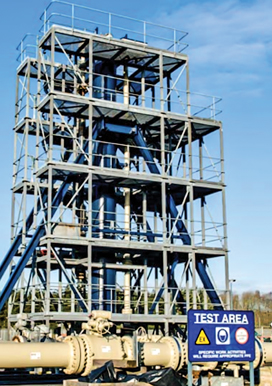 |
| Fig. 7. TRSSSV flow test rig at GL Nobel Denton. |
|
GL Nobel Denton. Located in Durham, UK, GL Nobel Denton’s flow center offers comprehensive testing and calibration facilities for various meters, filters, regulators, flow conditioners, pipe inner coatings and valves. The Slam Test Rig (Fig. 7) at the flow center can conduct high-rate slam tests at flowrates in excess of 400 MMcfgd and a flow velocity of more than 200 fps. Similar to the facility at SwRI, the TRSSSV is rigged up vertically in the test rig, and the valve is operated remotely by applying hydraulic pressure through a ¼-in. control line.
Instead of using nitrogen, the facility uses natural gas from the UK national grid, which is re-injected into the local gas distribution grid after passing through the valve. The use of gas from the grid eliminates the constraint of gas volume, allowing high flowrates to be achieved. The grid pressure limits the maximum gas pressure available for the test, which is in the range of 750 psi. Therefore, while it is possible to achieve much higher gas flowrates and velocities, as compared to SwRI, the gas pressure is significantly lower. The pressure differential between national and local gas grids is usually sufficient to achieve these high flowrates. Depending upon the actual grid pressures at the time of the test, and the desired flowrates, the facility can manage the downstream grid pressure, so that the gas flowrate can be allowed to stabilize at the desired value before initiating valve closure.
The facility is equipped with various pressure sensors to monitor the gas and hydraulic oil pressures required to operate the TRSSSV. In addition to other sensors, the facility also uses a pressure sensor at the hydraulic control line very close to the TRSSSV (approximately 6 in. to 1 ft away). This pressure sensor played a critical role in understanding system behavior at slam closure and will be discussed later.
The facility is not equipped to perform a pressure test at pressures higher than the normal gas grid pressure of approximately 750 psi. Therefore, the TRSSSV has to be transported to a different location for post-slam pressure testing. Also, similar to SwRI, the facility is not equipped to strip the valve for visual inspection.
SLAM TEST DESIGN
As mentioned earlier, subject reservoirs have initial pressures in the 10,000-psi range, which will decline to less than 1,500 psi before abandonment. Expected gas velocities during the early life of the wells at 400 MMcfd are calculated to be in the range of 45 fps, with well flowing pressures of more than 8,000 psi. During mid-to-late life, the highest calculated gas velocity at 350MMcfd is in excess of 160 fps, with flowing wellhead pressure of more than 1,500 psi.
With the given capabilities and limitations of both test facilities described above, it was not possible to test the TRSSSV at the flow conditions to which it will be subjected over the lives of the completions. It was, therefore decided to slam-test the TRSSSV at both facilities to take advantage of their maximum, respective pressure and flow capabilities.
Gas slam test procedure at SwRI. The following steps were taken at SwRI:
- Open and close the TRSSSV three times at ambient pressure and temperature. Record the full-open and full-closed control line pressures, and the times to close. Compare the values against the design pressure to open and close.
- Apply 200-psi nitrogen below the flapper, and measure flapper leakage, if any.
- Apply maximum available system pressure (approximately 2,500 psi) below the flapper, and measure flapper leakage, if any.
- Close test system above the TRSSSV.
- Open the TRSSSV, utilizing equalizing mechanism.
- Set the flow control to provide maximum gas flow possible.
- Open the gas flow valve, and adjust to maximum gas flow. Using data acquisition, record the flowing pressure, gas flow rate, and velocity.
- Bleed control line hydraulic pressure, to close the TRSSSV, and record closure time.
- Adjust and maintain upstream nitrogen pressure of 1,200 psi below flapper, and measure flapper leakage after stabilization. Record leakage rate.
- Bleed all pressures to zero.
- Repeat above steps, two or more times, to achieve maximum flowrate, velocity and pressure at valve closure.
- Bleed all pressures to zero.
Note: Do not cycle the TRSSSV after the last slam.
- Remove the valve from the flow test fixture, and move it to a pressure test chamber for a 10,000-psi flapper leak test.
- Pressure-test the TRSSSV across flapper, to 10,000 psi, using nitrogen.
- While maintaining 10,000 psi below the flapper, measure flapper leakage.
- Bleed all pressures to zero.
- Open and close the TRSSSV three times. Record the full-open and full-closed control line pressures. Compare the values against the design pressure to open and close.
- Drift the valve with the appropriate size drift.
- Rig down and return the TRSSSV to the vendor facility for disassembly and evaluation.
Gas slam test procedure at GL Nobel Denton. The following steps were taken at GL Nobel Denton:
- Open and close the TRSSSV three times at ambient pressure and temperature. Record the full-open and full-closed control line pressures, and the time to close. Compare the values against the design pressure to open and close.
- The leakage rate should be checked after each slam at high pressure (max. available facility test pressure).
- Using the maximum available facility test pressure, carry out a minimum of one slam closure at a flow velocity of 100 fps and two slam closures at flow velocities of ≥ 200 fps, and record corresponding flowrates.
- Utilize the equalizing mechanism to open the valve after each slam, except the last slam, after which the valve should be left closed.
- Remove the valve from the flow test fixture and transport it to the appropriate pressure test facility.
- Pressure-test the TRSSSV flapper at 750 psi and 10,000 psi. The leakage rate should be noted after each test.
- Once the pressure test is complete, cycle the valve (open/closed) at ambient pressure, utilizing the valve equalizing mechanism and record (open/closed) pressures.
- Drift the valve with the appropriate size drift.
- Disassemble the valve and perform a visual inspection.
Acceptance criteria. The following criteria should be followed for TRSSSV acceptance:
- The valve should hold the applied pressure after each slam test. Any leakage should not exceed the acceptable rate of 15 scfm, as per RP API 14B.
- The time between releases of hydraulic pressure to valve closure (during slam closure) should be consistent, and within the acceptable limit of 15 sec or less, per the Spec API 14A.
- The hydraulic pressure required to cycle the valve after each slam should be within ± 10% of its initial and normal operating pressure, as specified in Spec API 14A. Any changes in opening and closing pressure and/ or volume of hydraulic oil required to open or close the valve; any other abnormal behavior; or delays during the valve function; should be noted and recorded.
- The equalizing mechanism should function normally during pressure equalization.
- The drift should pass normally without any obstruction.
TEST RESULTS
Results from the testing procedures at the two locations are detailed below.
SwRI test results. TRSSSVs from the two selected vendors were tested successfully at SwRI in December 2011. Various attempts had to be made to achieve the combination of maximum possible flowrate and pressure. Maximum flowrate achieved during the slam closures 195 MMcfgd to 220 MMcfgd, with gas upstream pressure of 2,200 to 2,600 psi at the time of slam closure. Maximum gas velocity achieved at slam closure was 43 fps, which compares well with early-life conditions of the subject completions, albeit with a much lower corresponding pressure.
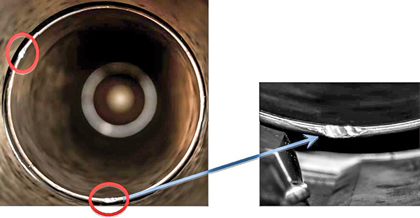 |
| Fig. 8. Damage to flow tube after slam closure test at SwRI. |
|
Both valves were pressure tested successfully to 10,000 psi with nitrogen after the slam test, and cycled open and closed with acceptable variations in hydraulic opening pressures. No significant damage was reported to the valve internals upon inspection. Minor damage to the flow tube was seen on one of the valves (Fig. 8), but as the valve cycled open/closed with acceptable hydraulic pressure and drifted successfully, the tests were considered successful.
GL Nobel Denton test results. The first slam test for Company A’s valve at GL Nobel Denton was conducted to a maximum flow velocity of 134 fps. The corresponding gas flowrate and pressure achieved were 252 MMcfd and 750 psi. The flapper leak rate after the slam with 750 psi was in excess of the acceptable leak rate and, therefore, further testing of the valve was stopped. The valve was returned to the vendor facility and stripped down for inspection. Valve internals were found to be generally in good condition, except the equalizing mechanism in the flapper. The equalizing valve was found to be stuck in the open position, due to deformation of the valve and the flapper area around it. The equalizing mechanism was modified by adding additional recess area around the equalizing valve, and it worked successfully during all subsequent tests.
During the second attempt to test Company A’s valve, the first two slam closures were carried out successfully at 163 fps and 225 fps, with corresponding flowrates of 342 and 445 MMcfgd. During the third attempt to slam close the valve at 229 fps (451 MMcfgd), the valve failed to close, when the control line hydraulic pressure was released to initiate closure. The valve remained open and continued flowing until gas velocity was dropped to 148 fps (321 MMcfgd), at which point the valve slammed closed.
One more attempt was made to conduct slam closure with the same results. The valve, once again, failed to close when hydraulic pressure was bled off to initiate closure. The valve did not close until the flowrate was dropped from 445 to 342 MMcfgd. The test was abandoned, at this point, for investigation.
It was determined that the flapper’s geometry, combined with the aerodynamic forces inside the valve, was preventing the valve from closing at high flowrates and velocities. The same phenomenon had been reported previously during slam testing of smaller size valves.4 The TRSSSV flapper was modified by milling additional flats on the back to improve the flow dynamic around the flapper, which resolved the issue, and the valve closed successfully in all subsequent tests.
The third, and last, test for Company A was carried out successfully, after which the valve was pressure-tested to 10,000 psi with nitrogen, cycled open and closed, with normal hydraulic pressure, and no significant damage to the valve internals was observed.
The first slam test for Company B’s valve was carried out with three slam closures at 109 MMcfgd (50 fps), 216 MMcfgd (100 fps) and 388 MMcfgd (194 fps). The valve closed normally during all three tests but it had a significant leak after the third slam, with only 750-psi test pressure. The valve was shipped to the vendor’s pressure test facility, but no attempt was made to pressure-test the valve, as it was not expected to hold pressure.
The valve required excessive hydraulic pressure to open for the first time, but, thereafter, it operated with normal hydraulic pressure.
Upon inspection, it was discovered that some of the hard facing material used on the flow tube for this prototype valve had peeled off and was caught between the flapper and the flapper base, causing the valve to leak, and the hinge pin for the flapper was found to be broken. Minor damage to the valve equalizing mechanism was observed, but the equalizing system did not cause the leak. To rectify these problems, the flow tube face was replaced with actual production valve material, and the hinge pin was redesigned with higher-strength material.
Another phenomenon witnessed during the slam tests was the high-pressure spike in the hydraulic control line at the time of slam closure. As mentioned earlier, the TRSSSV is opened by applying hydraulic pressure through a small control line, which pushes down a piston against a spring to move down the flow tube, which opens the flapper. The hydraulic pressure required to open the valve is directly proportional to the gas pressure in the tubing, i.e. the higher the pressure in the tubing, the higher the hydraulic pressure required to open the valve, and vice versa.
At the time of slam closure, hydraulic pressure is bled off at the pressure source to initiate valve closure. During closure at high velocities, as the flapper gets caught in the gas flow stream, the flapper starts to push the pistons back, forcing the hydraulic fluid out of the valve hydraulic chamber and into the small control line at an extremely high rate. Due to the extreme velocities, the rate at which the hydraulic fluid is forced back into the small control line caused the pressure to spike for a fraction of a second. The pressure sensor installed approximately 6 in. away from the TRSSSV control line connection recorded extremely high pressure spikes at the time of slam closure. While the pressure spike was short-lived (less than 1/10 of a second), it was high enough to cause the hydraulic connection in Company B’s valve to break.
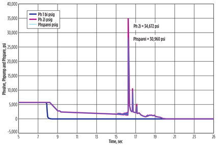 |
| Fig. 9. A control line pressure spike recorded at the TRSSSV during slam closure at GL Nobel Denton. |
|
The maximum pressure spike recorded for Company B was in excess of 30,000 psi (Fig. 9), whereas the maximum pressure spike recorded for Company A was in excess of 10,000 psi. Considering the fact that the tests were carried out at gas flowing pressure of only 750 psi, it was calculated that the pressure spike at actual well flowing pressures can exceed 15,000 psi.
To understand the dissipation of pressure spikes, additional sensors were added to the control line at distances of 10 ft and 50 ft from the TRSSSV. Pressure dissipated quickly, and, at a distance of 50 ft, the pressure spike was approximately 60% of the value seen at the valve. Also, there was no pressure spike at the hydraulic pump, about 2,000 ft away. As the TRSSSV setting depth for the subject completions is approximately 750 ft, it was concluded that the pressure spike would not travel to the surface, but the connection at the TRSSSV would, most certainly, see a pressure spike during a slam closure of the valve. If the control line fails at the TRSSSV, the TRSSSV cannot open and will require a rig-assisted workover to replace the valve.
Company B’s valve was modified to soften the impact at slam closure, and the spike pressure was brought down to about 15,000 psi. No modifications were made to Company A’s TRSSSV, and it was accepted with the understanding that during a slam closure, a pressure spike in excess of 15,000 psi could be expected. Also, to minimize the risk of control line connection failure, a 17,500-psi pressure test of the control line connection was conducted while installing the completion.
Two common types of control line hydraulic fluids in use are water-based and oil-based fluids. Water-based control line fluids are mostly used in subsea applications, because of their lower compressibility, as compared to oil-based hydraulic fluids. This helps to reduce the pressure transmission time in a long subsea umbilical. As water-based control line was used for the purpose of TRSSSV slam testing, an attempt was made to switch to water-based, with the assumption that the higher compressibility of oil-based fluid will help dampen the pressure spike. However, there was no evidence of a change in pressure spike with the water-based fluid.
X-MAS TREE AND CONTROL PANEL
As mentioned earlier, the hydraulic control line pressure required to open the TRSSSV needs to overcome the TRSSSV main spring force, and the pressure inside the tubing. The recommended pressure to hold the TRSSSV in the open position, during production, can be calculated as follows:
Hold open control line pressure = Pressure required to overcome the spring force + tubing pressure + 500 psi
For both valves, the pressure required to overcome the spring force was 2,000 psi. With the expected tubing pressure of roughly 9,000 psi, the control line pressure required to open the valve exceeded 10,000 psi.
Even though the X-Mas trees for these wells are rated to 10,000 psi, the control line connection, which passes through the X-Mas tree and the tubing hanger, had to be designed with a 15,000-psi pressure rating. Similarly, the wellhead control panel to operate the TRSSSV and the X-Mas tree valves was also designed to supply 15,000-psi control line fluid.
CONCLUSIONS
Full-scale test results confirmed that a 95/8-in. safety valve can be used to produce up to 400 MMcfgd at high velocities, and it can withstand forces imparted to it during slam closure under worst-case scenario conditions. Spec API 14A does not cover the TRSSSV slam testing requirements for completion sizes larger than 7 in. Therefore, slam testing of 95/8-in. TRSSSVs must be designed by the operator to best suit the well completions.
Two of the best facilities available in the world may not be able to meet the needs of large-bore TRSSSV slam testing. By utilizing the different capabilities of both facilities, a good compromise can be achieved, to ensure adequate TRSSSV testing, to withstand well conditions over the life of the completion.
It is important to monitor hydraulic control line pressure at the TRSSSV during slam closure, to ensure that the resulting pressure spike at the time of the slam is within acceptable range and can be managed. TRSSV flow dynamics must be considered for any newly designed valve, especially for valves designed to produce gas at high flowrates and velocities.
If the X-Mas tree working pressure rating is close to the expected wellhead pressure. the pressure rating for the TRSSSV control line connection at the production tree may need to be higher than the X-Mas tree working pressure rating. The hydraulic pressure required to open the TRSSSV after a slam closure may be significantly higher than normal operating pressures, and should be considered when designing the wellhead control panel. 
REFERENCES
1. McKenna, D. L., R. A. Sukup, T. Stambaugh and R. A. Biggs, “Arun Indonesia: Big-bore completion tool design”, OTC paper, presented at the Offshore Technology Conference, Houston, Texas, May 3-6, 1993.
2. D. Teng, G. Nettleshipl, S. Hicking and K. Hindmarsh, “High-rate gas well design: Issues and solutions—Goodwyn gas condensate, NWS, Australia,” SPE Paper 50081, presented at the SPE Asia Pacific Oil & Gas Conference and Exhibition, Perth, Australia, Oct. 12–14, 1998.
3. Clancey, B. M., A. S. D. Khemakhem, T. F. Bene and M. H. Schmidt, “Design, construction and optimization of big-bore gas wells in a giant offshore field,” presented at the SPE/IADC Drilling Conference, Amsterdam, The Netherlands, Feb. 20-22, 2007.
4. Aldridge, D. S., B. S. Shaw and S. A. Shirazi, “Economic, safety, and performance considerations for safety system design for large-bore gas completions,” OTC paper 11881, presented at the Offshore Technology Conference, Houston, Texas, May 1-4, 2000.
|
The author
MOHAMMAD ATHAR ALI is a petroleum engineer with Saudi Aramco Northern Area Production Engineering Gas Unit. In his current capacity, he looks after the development and production of Aramco’s three high-ressure, high-rate offshore gas fields. Prior to Aramco, he worked with Schlumberger for 23 years in various capacities. |
|


