KEITH HENG SENG WEE, KEVIN WOOD, DOUG FINLEY, Halliburton
Pressure maintenance support in mature fields, where permeability heterogeneity is present, requires proper distribution of injected water into the respective zones of interest. This process can be extremely challenging, if no method for allocating the proper amount of water into each zone is available. An operator in the South China Sea, who had initiated a water injection project using legacy single-string, two-zone completion technology, found itself in this predicament, since no selective control for pressure maintenance had been considered for the project.
During the past few years, the application of intelligent completion (IC) technology has increased rapidly. This acceptance has been due primarily to its proven capabilities for reservoir monitoring and corresponding optimization of well performance without interventions. Historically, the majority of IC applications have been in production wells; however, an increasing number of operators have started adopting IC technology for their injectors.
This article presents a case study in which IC technology was successfully applied to provide a solution for optimizing water injection. In addition to eliminating problems experienced with the incapability of the legacy completion technology to monitor water allocation and pressure maintenance for each zone, the IC technology allows selective well testing for each zone. By evaluating the reservoir properties and characteristics of each zone independently, an intelligent completion would provide another key benefit to the operator, since it would comply with the platform size restrictions for pumping equipment.
The article discusses field objectives, the conceptual design, the design obstacles, and the operational challenges experienced during the job execution.
BACKGROUND
Water-flooding experiences and lessons learned in this area of the South China Sea have been documented and presented. The injection well discussed in this article was in a mature field that had been producing for approximately seven years, and the production rates in other wells in this field had experienced a relatively steep production decline. Wellhead pressures varied in the injection wells in this field, anywhere from 500 to 2,300 psi. The variation experienced in wellhead injection pressures was a qualitative testament to the heterogeneity observed in the reservoirs of this field.
With a conventional single-string completion, the operator knew that the formation’s heterogeneity would prevent the desired distribution injection rates from entering Zones P and Q of the proposed well, since previously used legacy completion designs (Fig. 1) did not offer controlled zonal injection. The total injection rate was only 5,000 bwpd, and the operator knew that if a single-string completion with uncontrolled zonal injection was used, the injection rate would probably end up with 4,000 bwpd into one zone and only 1,000 bwpd into another. This would affect the field’s pressure maintenance, since the operator would have no injection control, and subsequently, no way to control water distribution. With this situation, it was very likely that reservoir pressure could not be sustained, much less increased. As a result, output from the oil wells in the field for those zones would continue to decline at a higher rate than desired.
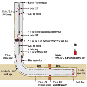 |
| Fig. 1. Conventional single-string completion with uncontrolled commingling injector. |
|
The only other option the operator had, in terms of other traditional completion designs, would be to use a dual-string completion. However, this would mean that they would need additional space and flowlines on the platform and wellhead area, and have the added complication of running a dual-string completion. With a single completion wellhead, only one “set” of flowlines is required, but for a dual-string completion, you must have two “sets” of flowlines. In addition to space restrictions, this would involve additional costs for the flowlines, labor, engineering etc.
Use of water injection during the early stage of a new reservoir’s development had been gaining popularity around the world. This was especially true in Saudi Arabia, where water injection was being used to improve oil recovery and for pressure maintenance.2 Also gaining popularity was the use of ICs in the fields with this type of reservoir, because this technology could balance II (for injectors) or PI (for producers) as a result of the heterogeneity between multiple reservoir layers.
The application in this case history was for a new, highly deviated, horizontal, two-zone, water injection well, utilizing an IC concept, that would be drilled from an platform offshore Vietnam. The ultimate goal for the IC’s design was not only to allow the injection rate into each zone to be remotely controlled. so that the injection’s efficiency could be maximized but also to remove the requirement for intervention into the well to control the flowrates to the zones.
The injection rate targeted was 5,000 bwpd. The injected fluid would be filtered seawater. The completion’s MD was 3,500 m. The choice for completing this well was 41/2-in., 12.6 lb/ft tubing and 95/8-in. casing. The 95/8-in. casing shoe would be immediately above the well’s build radius, into the highly deviated horizontal section (in the reservoir). The maximum dog-leg severity was 2.75o/100 ft. The horizontal section was to be completed as an open hole with 65/8-in. stand-alone screens (SAS). Two zones would be intercepted by the horizontal section.
OBJECTIVES
The primary objective for this completion was zonal control and optimization of the injected water in the two target zones. Hence, reservoir monitoring of each zone would be a key component to this completion. Additionally, to optimize the hydraulic horsepower required at surface for water injection, it was necessary to understand the injection profile that was expected for these two zones. Therefore, an extensive amount of pre-job planning and design had to be performed, to better understand each zone’s behavior during commingled water injection. Additionally, each zone had been planned to have discrete reservoir monitoring, to validate the water injection. By using an inflow control valve (ICV), discrete well testing of each zone would be possible, so that the injection over the course of this well’s life could be validated.
IC DESIGN CHALLENGES AND SOLUTIONS
Guidelines for design and prediction of water injection using ICs have been documented.3,4 A key component for pre-job planning and design was the choke trim that would be incorporated into the ICV. A choke trim was required that could account for the water injectivity into each zone over the well’s anticipated lifetime. First, the injectivity performance without zonal control was plotted with a range of reservoir properties for the two zones. Table 1 shows the parameters used for the nodal analysis. With these sensitivities, a plot of the expected performance was plotted and can be seen in Figs. 2 and 3.
| Table 1. Nodal analysis range parameters. |
|

|
Figure 2 shows the combined injectivity plot, assuming the Q sands were the most dominant with a reservoir pressure of 2,200 psi and a permeability of 84 mD. Total injection rates expected at a fixed flowing wellhead pressure were approximately 6,042 bwpd. Of this figure, 4,364 bwpd, or 72.2%, were expected to be injected into the Q zone, with the P zone expected to take only 1,678 bwpd, or 27.8%, when commingling injection was not controlled.
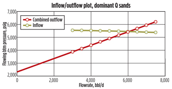 |
| Fig. 2. Combined injectivity plot for the zones with Q as the dominant sands. |
|
Figure 3 shows that with conditions reversed (P sand being dominant), with a reservoir pressure of 2.200 psi and permeability of 102 mD, the estimated injection ratesdo not change significantly, as 5,604 bwpd are expected. However, without zonal control, the P sands were expected to take in 5,300 bwpd, or 94.5%, with Q sands only taking in 304 bwpd, or 5.5%.
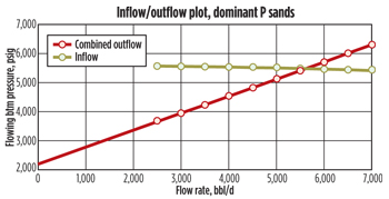 |
| Fig. 3. Combined injectivity plot for the two zones, considering P as the dominant sands. |
|
These two extreme scenarios were considered as “worst case” and were important for enabling the operator to manage the reservoir uncertainties. It is important to note that any potential damage to the formation would further impede injectivity.
Another challenge was that this project was fast-tracked. Therefore, existing designs of ICVs and flow trims had to be modified as much as possible. These modifications had to ensure that manufacturing lead times would be shortened. Based on the parameters agreed upon, plots of two different flow trims (Figs. 4 and 5) were carried out. The plots show a scenario, where Zone Q is the dominant sand, and the ICV is fully open with choking on Zone P. The flow trim design for this condition is flow trim A.
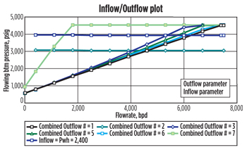 |
| Fig. 4. Poor level of control with flow trim A. |
|
 |
| Fig. 5. Combined injectivity plot for the two zones, considering P as the dominant sands. |
|
It can be seen clearly that the level of control exhibited with flow trim A under this condition is undesirable. Thus, another existing flow trim design, B, was chosen instead. Although the level of control is not ideal, due to the time constraints mentioned earlier, it was decided by the operator that they would proceed with flow trim B.
In addition to flow trims, the metallurgy selection was another concern for this completion. An evaluation of an injection water source sample revealed that 25 Cr alloy would be the material of choice. However, based on the operator’s experience, all previous water injectors had been plain L80 carbon steel. Thus, to maintain a cost-effective solution, a modification on an existing ICV design was engineered to have the base material as 4140 for all flow-wetted parts of Inconel material.
In addition to the intelligent flow control system, two gauge systems that measured pressure, only, with no downhole electronics, were employed for this completion (using a bottomhole chamber and capillary tubing filled with nitrogen). This type of system requires that capillary tubing be run from the gauge chamber downhole, all the way up to the tree and that each chamber would require its own capillary tubing. Ideally, electronic gauges would be chosen that could measure pressure and temperature upstream and downstream for each individual ICV. However, due to using the capillary gauge systems, and the limited penetrations at the tubing hanger and tree, the number of pressure points over two would be restricted. The way it was set-up, two pressure points of the top-most ICV that controlled zone P would be measured upstream and downstream. By using the equation below, it would be possible to estimate the rates being injected into zone P, and then, subtract this value from the total injection rates on surface.
Cv = q (SG / dp)1/2 (1)
where;
Cv = Flow Coefficient (2)
q = water flow
(U.S. gallons per minute) (3)
SG = specific gravity
(1 for water) (4)
dp = pressure drop (psi) (5)
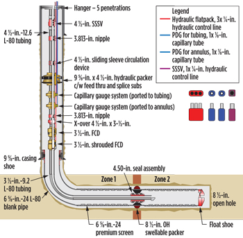
Figure 6 shows the completion design, which consists of an upper shrouded IC and a lower sand control-type completion.
 |
| Fig. 6. Two-zone intelligent water injector completion design. |
|
This concept is an adaptation of previously presented IC designs. The upper ICV will be the control valve for injection into the upper zone-1 (zone P), and the lower shrouded ICV will be the control valve for injection into the lower zone-2 (zone Q).
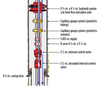 |
| Fig. 7. Expanded view of the completion schematic, showing the injection flow path through the ICVs. |
|
An expanded view of the ICV, shrouded ICV and gauge arrangements, which illustrate the flow path of the injection, as well as the measurement points of the downhole monitoring system, are shown in Fig. 7.
OPERATIONAL CHALLENGES AND SOLUTIONS
Since this was to be the first IC for this operator, a considerable amount of pre-planning, fitting and integration tests were required to ensure that the interface between the equipment was good.
Due to the use of the additional capillary tubing gauge system, it was determined that more feed-through areas were needed on the packers; this would require additional control lines that would take longer for the makeup of assemblies on the rig floor, because of the terminations, plumbing of lines etc. However, by using splice subs, the number of terminations and plumbing of lines required while on rig time could be minimized.
With a fast-track completion, lead times would be a challenge. Since this was the operator’s first intelligent well, it would be a start-up operation, where the service equipment, such as spoolers, sheaves and spreader bars, would have to be completely built. Therefore, a dedicated team was selected to work on the engineering and setting up of intelligent wells in Vietnam.
THE NEXT PHASE
Following the successful installation of the first injection well,5 an additional five wells were planned with the IC concept. The future, five-well campaign consists of two production wells and three injectors. Based on the previous experience of the first well, there were two primary improvements to the IC design of the subsequent wells. The two improvements were both related to flow control.
The first improvement was the ICV selection. In the first well, due to lead time constraints, a first-generation ICV was selected for quicker delivery. For the next phase, the second-generation ICV was selected. The second-generation ICV has been presented previously.6 The second-generation ICV offered several benefits over the previously installed ICV. The main highlight of this improvement to the completion design was the debris-tolerant feature. The second-generation ICV is designed with proprietary metal-to-metal sealing capabilities through an interference fit, rather than a single-point seal (as in the previous design). This feature was desirable for debris tolerance and a minimal amount of sand production. The second-generation ICV has been subjected to a rigorous qualification program, to qualify the valve. In addition to a stand-alone version of this improved ICV, the second-generation valve can also be adapted for shrouding and/or to include a deflector. For the next phase, the plans for completing the two producers were designed with shrouded and unshrouded variants of the second-generation ICV, Fig. 8.
 |
| Fig. 8. Intelligent completion concept for the producers. |
|
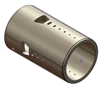
The second improvement was the selection of a flow trim for the ICV. Well simulations were performed to determine the optimal trim for both the producers and the injectors. For ease of manufacturing and operations, as well as prevention of any delay to the project, a single trim was needed that could successfully optimize both the producers and the injectors. Following the simulations, it was evident that a custom trim design would be the best fit solution. However, after examining existing designs, a suitable trim was found that could be successfully applied to both injectors and producers. The trim is made from tungsten carbide material, which makes it suitable for water, oil or gas. The trim would provide eight different flow positions for flow/injection optimization. Additionally, the trim can withstand a 5,000-psi unloading differential pressure rating, making it applicable for a wide range of applications (whether for injectors or producers). A schematic of the trim is shown in Fig. 9.
 |
| Fig. 9. Schematic of an ICV flow trim. |
|
SUMMARY
The intelligent completion of the first well, a water injection well, was successfully installed. Water injection operations have been initiated. To date, the injection performance of this well has been as predicted, and therefore, has been considered a success.
Continuous monitoring, and the capability to adjust the water injection into each zone, will enable the operator to fulfill the objectives for selective optimization of water injection into each zone. Five additional wells have been targeted for intelligent completion, using a similar concept as the initial water injection well.
A second-generation ICV has been incorporated into the intelligent completion design of the next five wells. Following extensive simulations, a single trim was selected that could optimize the injectors and the producers. This reduced delays to the project and simplified the application of the ICV for the next five wells. 
ACKNOWLEDGMENT
The authors wish to thank Halliburton for permission to publish this article. It has been adapted from a paper presented at the International Petroleum Technology Conference, Beijing, China, March 26-28, 2013.
REFERENCES
1. Dang, C.T.Q, N.T.B. Nguyen, W. Bae, Z. Chen, and T. H. Phung, “Lessons learned and experiences gained in developing waterflooding concepts of granite basement fractured reservoirs: 20 years of case study,” SPE paper 137651, Canadian Unconventional Resources & International Petroleum Conference, Calgary, Alberta, Canada, Oct. 19-21, 2010.
2. Al-Malki, S., M. M. Al-Burraikan, R. A. Abdulmohsin, R. Ahyed and H. Al-Hamzani, “I-field capabilities enable optimizing water injection strategies in Saudi Arabian newly developed oil fields,” SPE paper 120835, SPE Saudi Arabia Section Technical Symposium, Alkhobar, Saudi Arabia, May 10-12, 2008.
3. Sun, K., and M. Konopcynski, “Prediction of injection fluid distributions for multiple zones – intelligent injection system,” SPE paper 103078, SPE Annual Technical Conference and Exhibition, San Antonio, Texas, Sept. 24-27, 2006.
4. Allen, C., and A. Ajayi, “Process optimization guidelines in the design and operation of intelligent water injection wells,”SPE paper 136341, SPE Russia Oil and Gas Technical Conference and Exhibition, Moscow, Russia, Oct. 26-28, 2010.
5. Wee, K., and D. B. Finley, “Intelligent completion technology enables selective injection for pressure maintenance in mature field in South China Sea,” SPE paper 163314, SPE Kuwait International Petroleum Conference and Exhibition, Kuwait City, Kuwait, Dec. 10-12, 2012.
6. Rahman, J., C. Allen and G. Bhat, “Second-generation interval control valve (ICV) improves operational efficiency and inflow performance in intelligent completions,” SPE paper 150850, SPE North Africa Technical Conference and Exhibition, Cairo, Egypt, Feb. 20-22, 2012.
|
The author
KEITH WEE is a principle account representative for Halliburton Completion Tools, based in Brunei. He has 10-plus years of oilfield experience in field operations and business development roles. He spent seven years in perforating, permanent downhole monitoring and well performance modeling. For the past three years, he has been involved with completions and intelligent wells. Mr. Wee holds a BS degree in mechanical engineering from the Tenaga Nasional University in Malaysia.
KEVIN WOOD is the Asia Pacific Regional technical advisor for Halliburton Intelligent Well Completions, based in Kuala Lumpur. Over the last 15 years, he has been involved in wellbore monitoring and intelligent flow control technologies in a number of technical and business development positions. Previously, Mr. Wood held positions at Expro, QuantX, Weatherford and Ziebel, ranging from simple point PT gauges through to ESP monitoring, multi-drop gauges, fiber-optic multiphase flow, DTS and DAS.
DOUG FINLEY is the Halliburton Intelligent Well account leader for Malaysia, based in Kuala Lumpur. He has more than 29-years of diversified oilfield experience. He has spent the last six years working in intelligent well completions in the Asia-Pacific region. Doug holds a BS degree in petroleum engineering from the University of Missouri-Rolla. |
|

