ALI DANESHY, Daneshy Consultants International
There is general agreement that the combination of horizontal drilling and multiple hydraulic fracturing has been a game-changer in the oil and gas industry. Together, these technologies have transformed the energy posture of the U.S. by reducing the price of natural gas and causing a surplus gas supply, while reducing the imported oil volume. These changes have awakened the rest of the world to the potential of their unconventional resources. Efforts are already underway to use the same technology in other countries.
The oil and gas industry has used hydraulic fracturing for over 60 years and learned much about the technology and application. Until about a decade ago, the vast majority of these treatments were in vertical wells. While much of the technology and practices of vertical wells can be directly applied to horizontal well fracturing, there are areas of significant difference between the two systems. This article presents and discusses some of the important technical aspects, as well as the completion systems and tools, of horizontal well fracturing.
Fracture initiation in horizontal wells. It is well-known, and universally accepted, that hydraulic fractures propagate along the path of least resistance, which is perpendicular to the minimum in-situ principal stress. Through the years, we have learned that the vast majority of hydraulic fractures created by the oil and gas industry grow in a vertical plane (vertical fractures). In vertical wellbores, the well, itself, lies in the plane of the hydraulic fracture, causing initiation and extension of a longitudinal/axial fracture. In horizontal wells, fracture type depends on wellbore direction, with respect to the orientation of the least principal stress, as shown in Fig. 1.
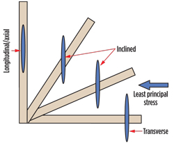 |
| Fig. 1. Fracture types in horizontal wells |
|
During fracture initiation, pressurizing the wellbore causes its expansion, and creation of tensile tangential stresses around it. Fluid pressure does not induce an axial stress on the borehole wall, Fig. 2. When the magnitude of the induced tangential stress exceeds the tensile strength of the formation, an axial/longitudinal fracture initiates along the borehole axis. If the least in-situ principal stress is perpendicular to the borehole axis, the axially initiated fracture continues to propagate axially/longitudinally. However, if this stress is not perpendicular to the borehole axis, then the axially-initiated fracture will have to reorient itself to follow the path of least resistance.
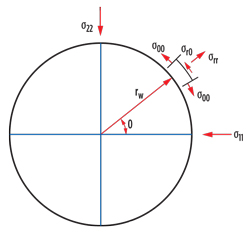 |
| Fig. 2. Stress distribution around the borehole |
|
Reorientation of the fracture can complicate fracturing of horizontal wells. In the laboratory test shown in Fig. 3, the applied stresses were perpendicular to each face of the rectangular block. The wellbore is inclined, with respect to these stresses, and can be seen in the middle of the block. The test shows an axially-initiated fracture that later reoriented itself to become perpendicular to the least principal stress, which in this case was along the length of the sample. The test also shows two different modes of reorientation within the same block; a sharp turn on the right, and a gradual turn on the left side. Thus, the natural tendency of a horizontal well is to promote axial fracture initiation. What complicates this situation even further, is that the two reoriented fractures will eventually have to coalesce to form a single fracture.
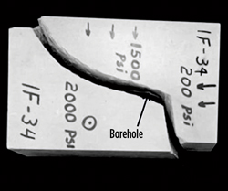 |
| Fig. 3. Effect of borehole on fracture initiation |
|
There are a few factors that can change the fracture initiation process. The most prominent of these is the presence of open, natural fractures. If the fracturing fluid can penetrate a natural fracture, its pressure induces stresses around, and at the tip of, the natural fracture, thus changing the stress pattern around the wellbore. Existence of a transverse natural fracture with sufficient surface area can cause direct initiation of a transverse fracture without undergoing any reorientation, as shown in Fig. 4. It should be noted that natural fractures are equally effective in promoting any other type of fracture. An axial or inclined natural fracture can easily become the source of an axial or inclined fracture initiation. Since natural fractures usually have random orientation and sizes, it is not reasonable to assume that they will only promote transverse fractures.
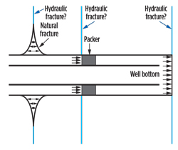 |
| Fig. 4. Factors promoting transverse fracture initiation |
|
Another source of transverse fracture initiation is the presence of openhole packers, Fig. 4. The force acting on the open face of these packers will induce an axial stress at the seating point of the packers, which will, in turn, promote transverse fracture initiation. In this case, the location of the transverse fracture will be at, or very near, the seating point of the packer, Fig. 4. The forces acting on the bottom of the open hole can also promote initiation of a transverse fracture.
Each of these mechanisms has additional effects on hydraulic fracturing that need to be recognized and taken into account. If natural fractures are the source of transverse fracturing, then the location of the hydraulic fracture will be random and out of our control or influence. Furthermore, in long, open horizontal sections, it is possible to create more than one fracture. Fractures initiated by packers will be very close to the packer, itself. Both these effects can interfere with the planned orderly location of fractures and reservoir drainage. An advantage of fracturing from open holes is that the reoriented fracture will intersect the open hole and, thus, regardless of the fracture type, there will exist a direct connection with the wellbore and the fracture.
In cased and cemented completions, the initiation of fractures is highly influenced by perforation details. The recommended practice is to place the perforations as closely bunched together as possible. It is common to have clusters of six shots per foot with 60o phasing. Fracture initiation from perforated, cased horizontal wells is more complex than open holes. Field measurements show that many such fractures initiate axially, too. Furthermore, often only a limited number of perforations are connected to the fracture and capable of transmitting the fracturing slurry. This can result in occasional early screen-out and inability to pump higher proppant concentrations during the job.
COMPLETION SYSTEMS
Horizontal wells use one of two basic types of completion—openhole (with or without a liner), or cased and cemented hole. In the case of a mechanically stable borehole, one has the choice of either completion. Otherwise, a cemented liner is the only option. Interestingly, field experience shows that many horizontal wells are quite stable and can be completed openhole.
Openhole fracturing systems. The basic feature of all these completions is that fracturing fluid is in direct contact with the formation. Below, we discuss more popular completion options.
In sliding sleeve completions, the wellbore is divided into multiple segments, using open-hole packers that are mounted on a liner. The most common liner sizes are 4½-in. and 5½-in. Each sleeve assembly includes several frac ports that are covered by the sleeve and closed at the start of operations. These sleeves are opened sequentially for fracturing, starting from the toe of the horizontal well and moving toward the heel. One popular mechanism for opening the ports is dropping balls, Fig. 5. In this system, the seating of the ball at the end of each sleeve creates a differential pressure, which then slides the sleeve and exposes the frac ports. Each separate ball is pumped with the fracturing fluid, and at an appropriate time. Once a set of ports is opened by the sliding sleeve, the injected fluid moves into the annulus between the liner and open hole, and creates the hydraulic fracture(s).
 |
| Fig. 5. Ball-activated sliding sleeve completion system |
|
Very shortly after the planned volume of fluid and proppant is pumped into this stage, the next-largest size of ball is dropped. The seating of this ball isolates the previous zone, opens the next ports and allows fracturing of the next zone. Continuous injection of fluid, proppant and dropping of the balls allows creation of at least one fracture in each isolated segment of the horizontal well.
Notable, positive features of the ball-activated sliding sleeve systems include:
- Continuous injection, thus shorter fracturing times.
- There is no need for wellbore re-entry between different stages to mechanically isolate them. This makes this system suitable for very long horizontal wells.
- Reservoir fluid production along the open-hole section. This can become significant for heavily naturally fractured formations.
Other features of these systems include:
- Considerable operational difficulty, in case of screen-out near the toe.
- Complex hydraulics requiring close attention to rates and pressures, so that sleeves are not accidentally shifted during fluid injection.
- Requirement for gauged holes, to allow interval isolation by open-hole packers.
- Attention to the ball dropping sequence, to ensure the correct size of ball is used for each stage.
Limited wellbore access, due to the sleeves. However, in many systems, the internal completion is milled shortly after fracturing operations, to allow full-bore access for clean-out and production
Another method of opening sleeves is a mechanical tool installed on coiled tubing or a workover string. The sequence of operations is the same as above. At the end of each stage, the mechanical tool shifts the corresponding sleeve and closes its ports. It then shifts the next upstream sleeve and opens its ports for fracturing the next stage. The benefits are full-bore access and ability to circulate proppant out of the well, in case of a screen-out. However, these treatments take longer than ball-activated systems.
Another system of openhole fracturing consists of hydra-jet perforating through a coiled tubing string, and slurry injection through either the same coiled tubing or in the openhole annulus, Fig. 6. Benefits include exact fracture location, elimination of openhole packers, and the high likelihood of simple fracture initiation, perpendicular to the least principal stress, bottomhole (BH) pressure monitoring through the dead string, and an ability to quickly manipulate the downhole slurry mixture by changing injection from the active conduit to the dead string. The presence of coiled tubing is also helpful for wellbore clean-out, in case of screen-out. Its two main disadvantages are propensity to proppant flowback, and rate limitation, due to injection through coiled tubing or the annulus.
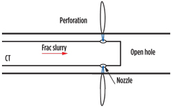 |
| Fig. 6. Dual-injection completion in open holes |
|
Cemented liner completions. The most popular of these systems is called Plug & Perf. A schematic of this completion is presented in Fig. 7. In this system, fracturing is done in multiple stages, with bridge plugs providing isolation between stages. At the start of each fracturing stage, an assembly consisting of a plug and perforation guns is placed (usually pumped) downhole with a wireline at the desired location. The plug is set, and perforation guns are fired at the planned sequence.
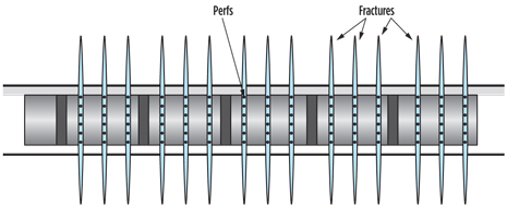 |
| Fig. 7. Schematic of a Plug & Perf completion |
|
The perforations are bunched together in clusters. The distance between these clusters can be selected, based on operator preference, but it is usually in the range of 50 to 200 ft. The more common number of clusters is three to six. The treatment design is based on a limited entry technique, where the number of perforations is determined, based on the planned injection rate, such that, on average, each perforation gets 1.5 to 2.5 bpm of injection. For example, for an injection rate of 60 bpm, one may plan to have 30 total perforations in three clusters, with each cluster having 10 perforations and covering a 2-ft interval, with a separation of 150 ft between clusters. After the perforation guns have been fired, the perforating wireline is pulled out, and the plug is isolated from the previous interval (usually by dropping and pumping a ball that seats in an opening in the middle of the plug). This interval is then fractured, as planned. The sequence of setting a plug, perforating, sealing the plug, and fracturing, is repeated multiple times until the entire horizontal well is fractured.
One noteworthy feature of this completion system is a large number of fractures. For example, if one fractures the well in 20 stages, with each stage having four clusters/fractures, the total number of fractures can be as large as 80. Another feature is resilience. The presence of multiple fractures means that if the proppant obstructs the path of flow in one fracture, the increased wellbore fluid pressure will distribute the fluid to other perforations/fractures. In actual operations, it is not uncommon to have only a portion of total perforations taking fluid. Sometimes, an entire cluster may not be fractured at all. Increasing wellbore pressure can cause breakdown of other perforations or clusters, thus causing a more uniform fluid and proppant distribution. Looking at this from a different perspective, screen-out in one entire segment means an inability to inject into all of its fractures. As long as any of these fractures is capable of extending, one will be able to continue fluid injection, albeit at a lower rate.
A third feature is unequal proppant distribution within fractures, in each stage. The technical basis for limited entry design is equal fluid distribution within different fractures. But, proppant distribution in these fractures is different than fluid distribution. The reason is that, because of its higher density and mass, the proppant can not redirect its flow path as easily as the fluid, when it approaches perforations. The result is that the first fracture gets the least percentage of the proppant, and this percentage increases in each subsequent stage, with the last fracture getting much more than its fluid share, as shown in Fig. 8. Another factor that contributes to this uneven proppant distribution is the flow velocity in the horizontal section, which decreases after each fracture.
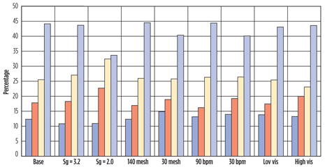 |
| Fig. 8. Proppant distribution in limited-entry treatments |
|
The combination of sliding sleeves and frac ports can also be used in wells with cemented liners. The sleeves can be opened by dropping balls (similar to the open-hole case), or hydraulically by fluid pressure inside the wellbore. In the systems, using ball drop isolation between stages is accomplished by seating of the ball in the center of the sleeve. This introduces the same limitations discussed in the open-hole case. In the hydraulic systems, the completion assembly is deployed downhole with coiled tubing. Isolation between stages is secured with a resettable bridge plug, which is located close to the end of the completion assembly. Fracturing is performed by pumping in the annulus, while the coiled tubing helps monitor the BH fracturing pressure variations. Many of these types of completions also have the capability to perforate the well by hydra-jetting through the coiled tubing. Noteworthy benefits of these systems are faster operations, flexibility in case of screen-out (cleaning the wellbore by fluid circulation), ability to add more stages by hydra-jet perforating, and monitoring BH pressure via the dead string. However, the use of coiled tubing limits the injection rate and total reach of the system.
Another system available for cemented liners is commercially known as Mongoose. The downhole system is deployed, using coiled tubing. Isolation between fractures uses a resettable packer. Perforations are done by hydra-jetting through the coiled tubing. Fracturing slurry is pumped through the coiled tubing/liner annulus, while BH pressure changes are monitored through the coiled tubing. Benefits and limitations are very similar to other completions using coiled tubing.
Some of the available systems for isolation between stages rely on screening out at the end of each fracture. These completions also use hydra-jet perforations through coiled tubing. This allows accurately locates the fracture. In one configuration of these systems, the fracturing slurry is also pumped through coiled tubing and through the same nozzles used for perforating. In another system, the fracturing slurry is pumped through the coiled tubing/cemented liner annulus. Screen-out at the end of each stage can be done, either by pumping slurry with very high proppant concentration, or, by mixture of different proppants. In both systems, the coiled tubing is used at the end of all fracturing operations to wash proppant out of the cemented liner. Benefits and limitations are very similar to those listed earlier using coiled tubing.
DIAGNOSTIC TOOLS
Similar to other aspects of horizontal well systems, diagnostic tools have changed considerably and progressed remarkably. Several are discussed below.
Microseismic fracture mapping. This is the most popular system for determining fracture orientation, which is a very important in planning and development of horizontal wells. In addition, systems providers also claim to be able to determine fracture length, height, and reservoir drainage volume. In general orientation, results obtained through microseismic mapping are more reliable than other results.
Proppant tracer survey. Very small volume of radioactive beads is mixed with proppant and injected into the well. Mixing a different tracer during adjacent fracture stages allows monitoring of the fracture's near-wellbore growth pattern. Detection of the proppant can sometimes yield very valuable information regarding wellbore and completion integrity and stability. Its main disadvantage is its shallow depth of investigation (around 1 ft into the formation). This is one of the best tools to determine which perforation clusters have been fractured, the type of fracture (axial or non-axial), which openhole segments have been fractured, fracture migration between stages, etc.
Liquid tracer survey. One of the questions in horizontal wells is the pattern and distribution of returned fracturing fluid. Liquid tracers make this possible. A different tracer is mixed with the fracturing fluid during each stage. Laboratory analysis of the returned fluid makes it possible to determine when, and how much of, the fluid pumped during each stage is flowing back.
Fracturing pressure interference. One of the most interesting consequences of horizontal well fracturing has been the high incidence of wellbore-to-wellbore communication via the created fractures. This is the result of three specific actions by producers; injection of large volumes of fluid, preference for transverse fracturing, and shorter spacing between offset wells. In the early days of fracturing, the communication resulted in flow of fluid, and sometimes proppant from the offset wells, which occasionally killed production. Today, the common approach is to close-in the offset wells, either at the surface or bottomhole, while fracturing is in progress. Placing a pressure gauge in the offset wells allows detection of time and intensity of pressure interference. These data can then be analyzed to determine fracture orientation, length, number of fractures, and sometimes even more. Although this analysis method is still in its infancy, it has shown great promise for determination and estimation of several critical fracturing parameters.
Fiber optics and distributed acoustic sensing. In this process, fiber optic and acoustic sensors are permanently embedded within the wellbore completion and used for observation of fracturing effects, and determination of its important parameters. Use of these systems requires advanced planning and careful coordination of all fracturing activities. The results of these surveys are massive volumes of electronic data that need to be stored, recalled and analyzed, as the observed events warrant. This means access to critical technical skills beyond fracturing, such as data management, and methodology for analysis of the results. These techniques also offer much hope that someday, in the near future, we will be able to not only diagnose our fracturing operations, but also be able to optimize the recovery of the reservoir fluids.
FUTURE OUTLOOK
Several crucial unknowns in fracturing hold the key to future step changes in the efficiency and effectiveness of the technology. Some of these are listed below.
Fracture growth pattern. Three patterns under discussion are simple, off-balance, and complex network, Fig. 9. Simple fracturing creates the longest, most conductive fractures. However, this pattern may not be realistic for a heterogeneous reservoir. An off-balance fracture grows in a narrow band, perpendicular to the least in-situ principal stress, but it can have numerous branches and many shear fractures, due to reservoir heterogeneity.
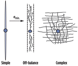 |
| Fig. 9. Fracture growth patterns |
|
As a result, it should be shorter than a simple fracture and have lower effective conductivity. A complex fracture network grows in many directions, and is assumed to predominantly connect pre-existing natural fractures with the main induced hydraulic fracture. Since the injected volume is divided into many fragments, this fracture should have the shortest length and least conductivity of the three models. Review of existing fracturing data provides partial support, as well as contradictions. For example, wellbores more than 1,000 ft apart are known to have been connected during the early stages of fracing and before injection of large fluid volumes. These occurrences favor, and off-balance fractures and contradict complex networks.
On the other hand, it is difficult to justify large flowrates produced from some of the very low-permeability reservoirs without accepting at least some degree of contribution from natural fractures. There are many instances, when hydraulic fracturing does not result in connecting adjacent offset wells, even when their separation is within the same range as others that do. This observation supports an off-balance growth mode that stipulates fracture growth within a relatively narrow band. If we accept that hydraulic fractures favor the path of least resistance, and are perpendicular to the least in-situ principal stress, it is very difficult to justify fractures spreading hundreds and sometimes thousands of feet in two orthogonal directions.
The justification offered by proponents of complex fracturing is that the two horizontal principal stresses are equal or very close to each other. However, this assumption is difficult to accept, since the structural geology of the earth favors unequal stress states. Microseismic mapping often supports the existence of complex fracture networks. But the same data also show signals that clearly could not be connected to an actual hydraulic fracture.
So, how do we distinguish a ghost from a real signal? Finding a reasonable answer has great impact on how we optimize production from our reservoirs. For example, with such high frequency of wellbore-to-wellbore communication, are we drilling them too close to each other? Are our fractures too closely spaced? Given the fact that the drilling and completion of a horizontal well can cost several million dollars, and that fracturing, alone, can be close to half the total well cost, even small changes can have significant financial impact. On the other hand, even a small reduction in production can be the difference between profit and loss. This situation is quite evident in gas reservoirs. With low gas prices, many reservoirs are not economical with present practices. Would a different well and fracture architecture make a difference?
Another issue that requires further discussion and deliberation is long-term production of mainly oil reservoirs. If the model most often cited by the industry (complex fracture network) is, in fact, the case, then would our present practices of connecting wellbores interfere with future water or polymer flooding? Would the difficulty inherent in some of our completion systems to isolate wellbore and fractures cause uncontrolled flow within the reservoir, resulting in early water or polymer flow through the path of least resistance? Would injection of a fluid into a reservoir that contains a network of intersecting fractures simply compress the fluid within the blocks, without sweeping out of the formation?
If a complex network is the real situation, is a re-evaluation of present completion practices in order? Should fracturing systems be changed to avoid or minimize wellbore-to-wellbore connection, such as attempting axial or inclined fracturing instead of transverse? Would the inherent difficulty of isolating wellbore segments in open-hole completions prove too hard or expensive for future operations? These are all issues that can have big impacts on of our industry. These need answers, and the sooner these are found, the better. 
|


