STEVE HESTER, President and CEO, 212 Resources
So far, so good is what you can safely say about the opportunity offered by massive exploitable shale gas resources in North America and potentially in many other areas of the world.
Despite this success story, the oil and gas industry knows that it must continue to work on ensuring that shale operations are economically and environmentally sustainable. In this context, probably the biggest challenge is how to safely manage the long-term water and waste management requirements of shale gas operations driven by hydraulic fracturing. There are issues here which, if not fully addressed, could quite conceivably derail future growth plans.
The wastewater associated with shale gas extraction is made up of flowback and produced water, which can contain high levels of total dissolved solids (TDS), fracturing fluid additives, metals, liquid petroleum products and naturally occurring radioactive materials (NORM). Flowback water is generated, when a natural gas well is being developed over a two-to-three-week period. Typically, this is 15%–20% of water used in the hydraulic fracturing process; the remainder of the water is absorbed into the subsurface. Produced water is developed, when the well goes into production and is an ongoing flow throughout the life of the reservoir.
An average Marcellus well generates approximately 1 million gal (24,000 bbl) of flowback water, and once in production, generates approximately 100 gal (2–6 bbl) of produced water per week. Produced water has constituent characteristics that are similar to those in flowback water, but at somewhat higher concentrations. One authoritative estimate of the scale involved is that the annual produced water from the Marcellus and deeper Utica shale plays, alone, will increase from the 2011 figure of 0.3 billion gal to 1.7 billion gal by 2020. That implies the need for responsible management through re-use or environmentally acceptable disposal of vast volumes of brine in flowback and produced water, plus all the drilling waste and sludge accrual.
REGULATORY BACKGROUND
The U.S. Environmental Protection Agency (EPA) recognizes that the current requirements that the oil and gas industry are following need to be reviewed. According to the EPA, while some of the wastewater from shale gas extraction is reused or re-injected, a significant amount still requires disposal. However, no comprehensive set of national standards exists at this time for the disposal of wastewater discharged from natural gas extraction. As a result, some shale gas wastewater is transported to treatment plants (publicly owned treatment works (POTWs) or private centralized waste treatment facilities, many of which are not properly equipped to treat this type of wastewater.
To ensure that wastewater receives proper treatment and can be properly handled by treatment plants, EPA, in consultation with stakeholders, industry and the public, is in the process of preparing new shale gas regulations, to be published in 2014.
However, the industry, itself, acknowledges that the technology dealing with shale gas wastewater has not kept pace with the revolution in shale gas exploration and production. It is being proactive in trying to promote solutions while time and public acceptance are on its side. This also makes business sense, given that an estimated 8% of total revenue from gas production over the life of a field development in the Marcellus shale could potentially be swallowed up by water and solid waste management. This figure comes from a major report published last year by the Gas Technology Institute (GTI), entitled, “Techno-economic Assessment of Water Management Solutions,” of which a public summary is available.
GTI's study of the Marcellus base case indicated that water management planning, alone, through the application of the right flow scheme or technology at the right time, could result in substantial savings and improved economic performance, as well as meet any environmental sustainability requirements.
The GTI report outlines (with estimated costs) four flow scheme options currently or potentially available in the industry. These include direct transportation of brines for disposal in a Class II deep well injection facility ($1.50–$3.50/bbl); in-field primary treatment, for the removal of suspended solids, oils and greases, microbes (through disinfection), and friction reducer polymer, prior to re-use of flowback water for the next frac job ($1.00–$5.00/bbl); near-field (within 20 mi of the fields) primary treatment, mainly for the above constituents, plus the possible removal of scale-forming constituents (e.g. calcium, magnesium, barium, etc.), followed by re-use of flowback water for the next frac job ($0.50–$4.00/bbl); and finally, primary treatment plus demineralization, using thermal evaporation/distillation processes, such as mechanical vapor recompression ($4.00–$6.50/bbl).
Perhaps a more significant finding from the GTI model is that the water management requirements of a development area change from year to year, and even decade to decade. A striking example is the ability to re-use frac flowback water in the early years of the development cycle. However, at a future point in the life cycle of the field, what’s termed the ‘cross-over point’ is reached. This is when demand for re-usable flowback is outstripped by continuing generation of flowback and produced water brines. The challenge then is to find an alternative to the re-use of the flowback option and disposal of brines. The GTI model also showed that much of the water flow, and more than two-thirds of the salt output, happens in the last half of the life-cycle. One clear implication from the report is that brine disposal and TDS removal facilities will need to increase substantially.
Produced and flowback water from the exploration and production of natural gas and oil will contain a number of constituents that may be considered “contamination” in certain concentrations. It has been observed that dissolved solids (commonly referred to as TDS) may vary from <7,000 ppm to over 100,000 ppm in a single eight-hour period. Natural minerals, present in the formation, may be released into the water, along with other fluids used in the production of the formation. Different fluid makeups may be experienced from well to well, due to geological conditions. These constantly changing conditions pose significant problems to traditional treatment methodologies.
TREATMENT PROCESS
In an effort to address the wide variations in constituent levels possible in produced and flowback water, 212 Resources combined a number of technologies into its treatment process. The first step is the removal and capture of free hydrocarbons. . Although other methods are available, simple gravity separation within a gun-barrel tank is often sufficient for initial separation of free hydrocarbons. Free oil and beorganic liquids float to the water surface in the tanks and are collected by an oil skimmer and transferred to a condensate or oil recovery tank. These oils and condensates have marketable value and are periodically transported to an oil recycling facility.
The clarified flowback and produced water are then pumped from the feed tanks to a processing unit. The 212 process, referred to as a POD, is, in fact, a patented system that boils water and re-condenses the steam into clean water. It does so by incorporating a dynamic inter-relationship of four operating loops.
The first loop feeds the system through two pre-heat exchangers that preheat the feed against the exiting clean water discharge and the exiting concentrated brine. In doing so, the clean water discharge is cooled and the feed wastewater is heated. This step recovers what is called ‘sensible’ heat, which is the heat required to raise water to the boiling point.
This preheated produced and flowback water enters a pressurized recirculation loop. Several critical steps occur within this loop. First, the fluid is further heated through a primary heat exchanger (described below) where it is directed to an evaporator. As steam is generated and removed from this loop, the remaining fluid becomes more concentrated with dissolved solids. This process repeats several times until the “concentrated bine” reaches the desired operating level. This loop is a key to the efficiency of the 212 system. By circulating at high flow rates in a pressurized system, a turbulent flow regime is established within the heat exchanger maximizing the heat transfer efficiency. The benefits of this design are maximum heat transfer efficiency and high brine concentration rates approaching saturation levels.
The third loop works in combination with the second, by evacuating the steam from the vessel with a steam pump that boosts the pressure of the steam (and increases the temperature). This steam, with its increased temperature, blows across the clean side of the primary heat exchanger used in the circulation loop. There, the steam condenses into clean water. As the steam condenses through this heat exchanger it releases the energy of vaporization which is transferred to the fluid in the circulation loop where the process repeats itself.
This heat recovery step is significant. In broad terms, approximately 10% of the total energy required to completely boil off a given quality of water is consumed in raising the ambient temperature to the boiling point temperature. The energy in this liquid phase is referred to as sensible heat. The energy required to completely evaporate a given quantity of water is approximately 90% of the total energy and is referred to as latent heat. The 212 system re-captures both the sensible heat and, more importantly, the latent heat of vaporization.
The fourth loop of the process incorporates a packed distillation column to separate and remove the light organic, alcohols, and other remaining components from the water. The recaptured distillate may have commercial value. The water from this point in the process is highly distilled and of a consistent, predictable quality. A portion of the remaining heat is then imparted into the preheat exchanger described in the first loop.
What is accomplished by 212 in the system design is a self-cleaning, highly efficient process that recovers both the sensible heat and the latent heat of vaporization. This enables extremely low operating costs and also facilitates the removal of suspended solids, alcohols and hydrocarbons along with the elimination of dissolved solids from the clean effluent stream. This process also results in highly concentrated brines approaching saturation levels.
FIELD EXPERIENCE
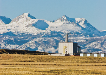
There is proven field experience with this technology. One E&P company used this technology while developing approximately 22,150 net acres in the western U.S. The development represents over 2,000 net drilling locations. Costs of the operation were being jeopardized by increasingly stringent regulations and no easy option to dispose of the waste water via re‐injection or open pit evaporation. The water management costs associated with trucking and disposal was threatening the economic viability of future field development.
Reviewing the available technology options, it was determined that water treated for discharge would be the most economical solution. To accomplish this task, new permitting regulations had to be addressed, effectively a rigorous assessment of whether the technology could achieve what it claimed. Permitting the facility required the coordination of local, state and federal agencies, and consisted of conditional use, oil and gas conservation location assessment, oil and gas conservation facility operation, air quality (Title V, due to co‐location with a compressor station), water quality, and Army Corps of Engineers point of discharge and storm water management permits.
The water treatment facility was designed to treat 5,000 bpd of produced/flowback water to NPDES (National Pollutant Discharge Elimination System) standards for discharge into a Class 1, cold water aquatic life stream that feeds into the upper Colorado River. It was estimated that the system would reduce daily truck traffic by 50 round trips (240 mi, each) significantly reducing transportation costs and enabling cost-effective development of the field.
Comprehensive testing was carried out, involving four independent environmental engineering groups to validate the system’s capability. A comprehensive report was generated listing all of the permit requirements, the feed characteristics, and the final discharge parameters. All discharge parameters were met at design process flows, including re‐mineralization of the water to ensure the proper chemical balance for creek discharge and agricultural use. As the requirements were to a Class 1 cold water aquatic life stream, the testing regimen included testing, known as the ‘WET Test’ (whole effluent toxicity). This test addresses the aggregate toxic effect to aquatic organisms from all pollutants contained in a facility's wastewater, measuring the CWA’s prohibition of the discharge of toxic pollutants in toxic amounts. WET tests measure wastewater's effects on specific test organisms' ability to survive, grow and reproduce. In operation, the plant has consistently met the permit requirements for this test.
This example shows that exceptionally high standards for produced and flowback water treatment can be economically achieved. It should be noted that conventional treatment facilities may check for free oil, TDS and RCRA (Resource Conservation and Recovery Act) metals. However, other contaminates are addressed in this system, such as NORMs, EDC (endocrine-disrupting compounds) and various aldehyde compounds commonly found in gas field-produced and/or flowback water.
The approach taken by the state regulatory agencies in permitting the facility ensured that the best management practices were in place to minimize the potential risks to the environment. A number of similar facilities have been installed in U.S. shale play basins by 212 Resources with the same detailed attention to permitting requirements and an eye on potential future environmental concerns.
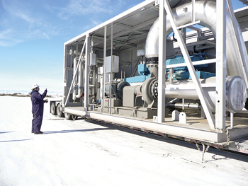
An important design feature of the treatment systems is that they are field-transportable, modular in design ‘PODS’ that can be located close to actual drilling and completion activities, Fig. 1. This significantly reduces costs associated with water sourcing, transportation, associated environmental risks, and ancillary expenses that are often overlooked, such as road maintenance.
 |
| Fig. 1. Field-transportable POD housing, MVR wastewater treatment unit. Photo courtesy of 212 Resources. |
|
The specific challenge in the Marcellus shale is that flowback and produced water typically contain very high concentrations of salts (TDS), often reaching 150,000+ ppm (seawater is approximately 33,000 ppm.). The MVR treatment process (Fig. 2) allows near-saturation level concentration of up to 300,000+ ppm TDS at elevated temperatures, which can reduce the waste stream by 50%.
 |
| Fig. 2. Inside the treatment train POD. Photo courtesy of 212 Resources. |
|
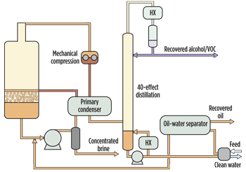
The process, itself, is designed to produce two effluent streams: consistent-quality water and highly concentrated brine, Fig. 3. It has proven possible to overcome consistency issues in the fluids returning to surface, which can vary widely in the consistency of dissolved solids and other elements potentially causing significant operational issues. Unlike most conventional water treatment processes, no elaborate front-end filtration system is needed. In addition, an integrated steam stripper system is designed to remove volatile organic chemicals (VOCs), alcohols and BTEX (benzene, toluene, ethylbenzene and xylenes) components.
 |
| Fig. 3. Diagram showing the treatment train and the outputs. |
|
In this case, the energy required to operate the units is typically wellhead natural gas. Also a high percentage of waste heat is recaptured and re-used to improve the efficiency of the operations. The system can operate off of grid power or electric power can be provided by lean-burn natural gas generators and used throughout the process. Ancillary benefits are that the recovery system significantly reduces the noise generated to less than 50 decibels at 200 ft and also lowers the exhaust temperature.
Other technologies will doubtlessly emerge, but at current pricing less than $3.00/bbl, this is one commercially viable solution for developing a critical global energy resource while providing an environmentally responsible and beneficial byproduct. 
|


