DAVID MENZIES, Fugro, and CAROLE RANIER, MatthewsDaniel
 |
| A spud can penetration curve can aid in the safe siting of a jackup rig. Photo courtesy of Fugro. |
|
For the operator, predicting foundation behavior is crucial to understanding the risks associated with placing a jackup rig at a designated location. For independent leg jackup rigs, this is even more important, as the legs serve as the foundation for the rig on location. To confirm a suitable foundation, the base of each leg is fitted with a spud can, a plate or cone designed to transfer the vertical loads into the seabed to the point of refusal by means of preloading. Spud cans are can be circular, square or polygonal, and they vary in size. The largest spud can being used, to date, is more than 20 m wide.
Spud cans apply pressures that vary from about 165 to 525 kilo-Newtons per square meter (kN/sq m), and the soil resistance must be known before a jackup can be placed safely on location. This allows the drilling contractor and operator to know how the spud cans will behave, as they follow the slope of the predicted penetration curve, and how deep they’ll penetrate.
The spud can penetration curve, where the soil resistance increases with the increasing depth, shows that foundation soils are adequate to support the legs without the chance of rapid (punch-through) penetration. However, locations with deep penetration would raise concerns about sufficient leg length to work at the location, possible spud can extraction problems, and the amount of time required to install and remove the spud cans.
Penetrations of about 35 m can occur in normally consolidated soil profiles for the more heavily loaded jackups. As the jackup’s hull draft reduces, load is transferred through the legs and spud cans into the soil. As the load increases, the spud cans penetrate deeper into the soil, until the soil provides sufficient resistance (bearing capacity) to support these loads.
Once the hull clears the water, the lightship-plus-variable load condition has been applied. To proof test the soil and ensure a safe foundation with a factor of safety, water is pumped from the sea into the tanks of the jackup’s hull. As these tanks fill with water, load is transferred into the soil. When the preload tanks are full, or the maximum designated load has been applied, the load is held for a designated period of time until no additional spud can penetration occurs.
This loading process is usually performed with an air gap specified in the rig’s approved Operational Manual (typically about 1.5 m) that reduces as the rig is pre-loaded. As the spud cans penetrate the soil, and the hull comes into contact with the water, the preload water is dumped from the tanks, the hull is raised back to a suitable air gap above the sea level as determined by the risk level of the soil conditions, and the preload process is repeated. This process continues until no additional penetration occurs, with the maximum load typically held for several hours.
SPUD CAN PENETRATION
An evaluation was performed for a Marathon LeTourneau (MLT) Design, Class 116-C independent mobile jackup, at a location that had one of the deepest spud can penetrations ever recorded. The location was in a region of the Gulf of Mexico (GOM), where high soil depositional rates allowed a thick layer of soft, under-consolidated clay sediment to rapidly accumulate over several hundred years. The condition of the soil was very weak, because of the high depositional rates, low permeability, and long drainage paths that prohibited the soil from reaching a stronger, normally consolidated state.
Spud can penetration curves were developed for the very soft-to-stiff, under-consolidated, highly plastic soil, as an aid to safely placing the rig on location, using conventional bearing capacity methods, making some accommodations for the predicted deep penetration. Deep spud can tip penetration in excess of 75 m was predicted. Spud can tip penetrations that ranged from 76.2 m to 78 m below the seafloor, or an equivalent depth of 5.6 times the spud can diameter, were measured. Locations where deep penetrations occur often see the spud cans slowly penetrate or creep into the soil while holding a constant load. However, the maximum preload was held until no additional spud can penetration occurred at this location.
DEEP SPUD CAN PENETRATION PROBLEMS
Areas of concern about placing the rig on location included limitations of the bearing capacity methods used to predict the very deep penetrations; questions regarding spud can and leg extraction; and the possibility of horizontal loads caused by near-surface soil movement induced by storm waves. The seafloor soil consists of pockets of very soft (very weak) clay that may act unstable and could move horizontally if subjected to cyclic loads from large waves during a hurricane.
The conventional bearing capacity methods used to investigate spud can penetration were not developed to predict penetrations as deep as experienced at this location. The bearing capacity methods are limited to an approximate depth equal to 2.5 times the spud can diameter, or a depth of 35 m for the 14-m-wide MLT 116-C spud cans placed at this location.
Despite depth limitations, conventional bearing capacity methods recommended in SNAME (2008) and the new ISO (2012) documents were applied to develop load-penetration curves for this location. Spud can and leg extraction were a concern for the 78-m embedment depth. The deep penetration and soil backfill on top of the spud cans exerts a pressure of 360kPa (equivalent load of 51MN) on the spud cans. The weight of the soil above the spud cans would need to be overcome, to extract the spud cans. Possible horizontal soil movement applied to the leg chords and trusses was also considered a potential risk to the rig. The horizontal movement of very soft surface soils has previously resulted in jackup rig and platform losses in these types of soils.
MLT 116-C PROPERTIES
The jackup rig placed at this location was a MLT Design, Class 116-C with three independent legs and cone-type spud can foundations. In plain view, the spud can was a dodecagonal shape but was modeled as a circle with a maximum horizontal cross-sectional area of 143.6 sq m and an inverted cone tip that extended 3.2 m below the maximum horizontal cross-sectional area. A plan and profile image of the MLT 116-C spud can is shown in Fig. 1. Initial and final penetrations, and the corresponding loads used to assess penetrations, were recorded. The applied loads and measured penetrations are presented in Table 1.
 |
|
Fig. 1. Boring log and interpreted soil properties
|
|
| Table 1. MLT 116-C loads and penetrations |
|

|
SOIL CONDITIONS
The site investigation consisted of one sample soil borehole that included downhole, in situ, vane shear, strength measurements. Some of the soil samples showed evidence of expansion, due to dissolved biogenic gases, which reduced sample quality so the in situ vane tests were performed. The log of boring and laboratory test results (boring log) is shown in Fig. 1. The interpreted soil properties used to develop the spud can load penetration curves are shown on the boring log and in Table 2.
| Table 2. Soil properties |
|

|
BEARING CAPACITY METHODS
A series of load-penetration curves was developed, using the different bearing capacity methods for the all-clay soil profile. The three bearing capacity methods include Skempton (1951), applied as per Young, et al. (1984), Houlsby and Martin (2003), and Hansen (1970). These methods are also presented in the SNAME (2008) and the new ISO 19905-1 (2012) documents. The bearing capacity methods are only briefly discussed here, but can be found in the paper by Menzies and Rainer-Lopez (2011). The bearing capacity methods utilize the soil properties and spud can dimensions to develop spud can load versus penetration curves, at different depths below the seabed, utilizing a “wished-in-place” technique.
The bearing capacity methods use the soil properties or parameters that include undrained shear strength and, to a lesser extent, the submerged unit weight to compute the load at different spud can depths. The bearing capacity methods are applied, utilizing the soil properties determined at the spud can maximum horizontal cross-sectional area, but the corresponding penetration depth is referenced to the deeper spud can tip; this usually equates to the jackup leg markings.
The bearing capacity methods in cohesive (clay) soil generally follow the form:
|
Soil (ground) resistance
|
=
|
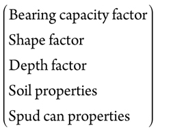
|
Spud can area
|
+
|
Buoyancy term
|
The factors and properties in the above equation are, generally, different for each of the bearing capacity methods. For instance, soil properties, such as undrained shear strength, can vary, from the strength value at the maximum horizontal spud can cross-sectional area, to a value that is averaged over a distance of one-half the depth of the spud can diameter below the maximum area.
To apply the bearing capacity methods, the maximum depth factors were used without modifications to determine the load values. The Houlsby and Martin method, recently adopted by the new ISO 19905-1 (2012) jackup site assessment document, uses additional factors to better account for differences in soil properties and spud can geometry.
Soil properties include the undrained shear strength, rate of shear strength increase with depth, and submerged unit weight determined from the geotechnical site investigation. Spud can properties include the maximum horizontal cross-sectional (plan) area, total volume, major cone tip angle, and a roughness factor. The spud can cone tip angle for the largest area shown on Fig. 2, and a roughness factor of 1.0, were employed in this study.
 |
| Fig. 2. MLT 116-C spud can |
|
The buoyancy term will have a large influence on the soil resistance, if the soil below the spud cans does not backflow on top of them. Hossain and Randolph (2009) developed a method to determine the maximum soil cavity depth that will form above the spud cans. The deeper the cavity, the greater the amount of displaced soil, which results in greater soil resistance and reduced spud can penetration. The buoyancy term also accounts for the resistance developed from the effective soil unit weight displacement by the embedded spud can. The buoyant force of only the embedded spud can, without the formation of a spud can cavity, was a small influence of less than 5% of the total soil resistance for this case.
One of the critical properties needed to accurately determine soil resistance in clay is the undrained shear strength. The undrained shear strength is determined from the geotechnical site investigation that varies in complexity from a single sample boring to multiple borings, with in situ tests that are integrated with geophysical data. The level of complexity is usually based on: regional experience, local regulator agency requirements, the amount of available historical information, and the history of spud can performance, particularly if foundation problems have occurred at or near the proposed location.
The undrained shear strength for this study was determined from one borehole, with laboratory tests performed on soil samples and in situ downhole vane tests. Downhole vane tests were performed to better assess in situ shear strength. In situ tests are preferred, as they provide results that are not influenced by sample disturbance.
PREDICTED PENETRATION CURVES
Three predicted load-penetration curves based on Skempton, Hansen, and Houlsby and Martin methods are presented in Fig. 3. Measured (recorded) penetrations are compared with the predicted curves in the figure. Generally, the predicted curves give relatively good agreement with the measured spud can penetrations. Reviewing Fig. 3, the Skempton method under-predicts the initial penetration but appears to better predict final penetrations. The Skempton bearing capacity depth factor was limited to a value of 9.0; that reduced the predicted penetration and unexpectedly provided a better fit with the measured values at deeper depths. The Hansen method predicts the initial penetration but over-predicts the final penetration. The Houlsby and Martin method gives the best fit, when the shear strength slope of 0.30 kPa/m of Stratum I is applied to produce the entire penetration curve. This approach provides the best fit for both the initial and final penetrations. The Houlsby and Martin curve was developed below 18.3-m penetration, where the shear strength slope was positive and linearly increasing with depth. However, the method over-predicts penetrations, if the larger shear strength slope value of 1.01 kPa/m below 53.0 m is used.
 |
| Fig. 3. Spud can penetration curves |
|
The Hossain and Randolph (2009) method predicts that a 3.0-m cavity will form above the spud can. However, the formation of a spud can cavity seems unlikely, as the recovered soil samples are so soft and under-consolidated that they were unable to support their own weights when removed from the water column. The influence of the formation of a 3.0-m cavity on the soil resistance at a depth of 78 m would be minimal and was ignored.
The jackup remained on this location for approximately four weeks, when the leg extraction process began. Despite having a soil effective overburden pressure of 360kPa (load of 51MN) applied to the top of each spud can, all three legs were extracted without any problems over several days. The relative ease of extraction was attributed to the short time that the rig spent on location; a new spud can jetting system in excellent working condition; and the very weak soil shear strength above the spud cans.
The MLT 116-C jackup worked at this location during the non-hurricane season, to limit the potential for soil movement effects. The jackup did not experience soil movement or any horizontal leg sway while on location. The short, four-week stay on location, positioning the spud cans in pockets of stronger and stable surface soil, and working on location during the non-hurricane season, reduced the potential for horizontal soil movement to occur.
LESSONS LEARNED
A spud can penetration curve was developed for a 53-m-thick deposit of weak, under-consolidated soil underlain by an older, stronger soil as an aid to safely placing the jackup on location. The load-penetration curves predicted that deep penetrations of more than 75 m would occur. For these predicted deep penetrations, the accuracy of the bearing capacity methods was uncertain, spud can and leg extraction problems were anticipated, and the potential for horizontal soil movement was considered a possible hazard.
Based on the load-penetration performance of the MLT 116-C jackup at this location, it was concluded that the bearing capacity methods recommended by Skempton and Hansen give reasonable penetration predictions, despite the depth limitations of these two methods. Additionally, the Houlsby and Martin method was developed below 18.3-m penetration and gave the best prediction when the shear strength slope at that depth was used to produce the entire penetration curve. The use of these bearing capacity methods should be further investigated before they are applied at locations where penetrations greater than a depth to spud can diameter ratio of 2.5 is exceeded.
The spud can penetration curves provided a prediction that was followed to provide a safe guide for rig installation. The maximum load was maintained on the spud cans until no further penetration occurred. A spud can cavity of 3 m was predicted to occur with the Hossain and Randolph (2009) method. The effect of the cavity on soil resistance at these deep penetrations was small and was ignored.
Spud can extraction was not a problem, despite 78 m of final penetration and the 360kPa effective soil pressure or an equivalent 51MN soil load placed on top of the spud cans. The spud cans were extracted in several days. The relative short stay on location, the new jetting system, and the very weak soil strength, contributed to the ease at which the spud cans were removed.
Pockets of very weak near-surface soil in this region had the potential for movement that would apply horizontal loads on the jackup’s leg trusses and braces. Movement of these very weak, near-surface soils is activated by large waves associated with hurricanes. The MLT 116-C jackup was on location during the non-hurricane season, and horizontal loads due to soil movements did not occur.
If the location had been presented for approval during hurricane season, an additional Marine Warranty Survey or review, with additional analyses to investigate horizontal soil loads against the legs of the jackup, would have been required. 
REFERENCES
1. Hansen, J.B., "A revised and extended formula for bearing capacity," Bulletin No. 28, Danish Geotechnical Institute, Copenhagen, pp. 5-11, 1970.
2. Houlsby, G.T., and C.M. Martin, "Undrained bearing capacity factors for conical footings on clay," Geotechnique, 53(5), pp. 513-520, 2003.
3. Hossain, M.S., and M.F Randolph "New mechanism-based design approach for spud can foundation on single layer clay," Journal Geotechnical and Geoenvironmental Engineering, ASCE, Vol. 135, No. 9, pp. 1264-1274, 2009.
4. ISO 19905-1, Petroleum and Natural Gas Industries – Site-specific assessment of mobile offshore units – Part 1: Jack-ups, First Edition, ISO/TC 67/SC 7, International Organization for Standardization, 2012.
5. Menzies, D., and C. Rainer-Lopez, "Four atypical jack-up rig foundation case histories," 13th International Conference, The Jack-Up Platform, Design, Construction & Operation, London, England, September 2011.
6. Skempton, A.W, "The bearing capacity of clays," Proceedings, Building Research Congress, Institute of Civil Engineers, London, pp. 180–183.
7. Society of Naval Architects of Marine Engineers - SNAME, Guidelines for site-specific assessment of mobile jackup units, SNAME T&R Bulletin 5-5A, Jersey City, New Jersey, 1st Edition – Rev. 3, March 2008.
8. Young, A.G., B. D. Remmes and B. J. Meyer, "Foundation performance of offshore jackup drilling rigs," Journal of Geotechnical Engineering, ASCE, 110 (7), pp. 841-859, 1984.
|
The author
DAVID MENZIES is an expert in the interpretation of soil conditions and jackup rig spud can penetration analyses. He holds BS and MS degrees from the University of Houston and is a Registered Professional Engineer in Texas. He has more than 25 years of domestic and international experience with Fugro in Houston, where he serves as a senior project manager. He is a member of the ISO jackup rig committee and has worked with most types of soils and jackup rigs.
CAROLE RAINER serves as vice president of MatthewsDaniel Houston and is a Warranty Certification manager for the Marine Division. She has had experience with the offshore and insurance industry, including the past 28 years in association with Matthews Daniel Company. |
|

