ERROL PINTO and JOSE MOTA, Shell Upstream Americas; JEFFERY GRABLE and DAVID WARD, Halliburton Energy Services
 |
|
|
Shell has been active in the Haynesville shale-gas play and has drilled both vertical and horizontal natural gas wells in DeSoto, Sabine, and Red River Parishes. Estimated recoverable reserves are as much as 60 Tcf (Hammes 2009), but drilling horizontal lateral sections presents extreme challenges with 16,500–18,500-ft measured-depth wells and flowing temperatures that can exceed 375°F at section TD and pressures in excess of 9,000 psi. With low natural gas prices in the U.S., reducing drilling costs by improving tool reliability is an essential requirement. In 2009, the Shell-Halliburton team set out a challenge to eliminate mud motor and MWD failures in the production interval. The team used a collaborative approach and applied root-cause failure analysis, new condition-based maintenance systems, and field-operation processes to systematically push MWD, mud motor, and LWD performance in this hostile environment.
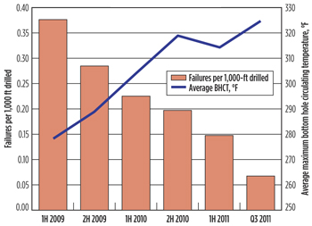
The team experienced close to 0.3 failures per 1,000-ft drilled, which was considered good for the industry at the time. The operator presented a challenge to eliminate all MWD, mud motor and LWD failures. Working closely, the team reduced tool failure rate over a two-year period by more than 80%, in spite of increasing average bottomhole circulating temperature.
WELL DELIVERY
Wells in the Haynesville can require directional drilling in the surface, intermediate, and production sections. Typical well designs call for directional step-outs of 1,000 ft in the surface and intermediate sections and 9°/100 ft build sections in the production interval. This article focuses on tool reliability in the production interval, which has enabled the drilling of multiple wells in less than 30 days from spud to rig release.
One of the key performance indicators used by the team to gauge performance is minimizing the number of days from spud to rig release. Subsequently, drilling the production interval with one BHA from drillout of the intermediate shoe to TD enables faster drilling times. The chosen mud motor for the production interval has been a variable-bend motor with a setting of 1.83°/100 ft. The team has evaluated several options in selecting the appropriate rubber and fit to improve performance.
Accurate lateral positioning can be achieved through geosteering, which is critically important to increasing the ultimate recovery of the wells. Consequently, while drilling, the use of advanced logging-while-drilling tools, such as azimuthal litho-density and resistivity, to complement gamma ray is not uncommon. However, for a majority of the wells, typical toolstrings consist of only directional tools and gamma ray.
Because drilling efficiency is essential when operating in the Haynesville, the service provider has made a variety of modifications and optimizations to increase tool reliability that will, in turn, drive greater efficiency. Subsequently, the MWD/LWD tools have evolved for this high-temperature environment, enabling extended runs.
SYSTEMATIC APPROACH
In the pursuit of drilling efficiency, the operator and service provider took up the challenge of drilling the entire production interval with a single bottomhole assembly. Under these conditions, the bottomhole assembly would be subjected to circulating in excess of 300 hr at temperatures exceeding 347°F (the operating limit of the tool). The challenge of delivering this goal was addressed in a systematic manner between the operator and the vendor that included improving communications between field, shop and office-based personnel, improvements in field and shop-based procedures, root-cause failure analysis and condition-based maintenance. The implementation of systematic field and shop-based procedures improved tool reliability, optimized tool setup, and helped develop new strategies to mitigate temperature.
SHOP-BASED PROCEDURES
Improving MWD tool reliability. Improvements in tool reliability were qualified through a rigorous testing schedule that consisted of operation in an environment with HPHT conditions, and validation of tool functionality after modifications were made to account for elevated bottomhole temperatures. A rigorous testing schedule in an adiabatic flow loop, allowed tool validation and functionality under HPHT conditions.
Optimization of tool setup is crucial to improve tool reliability, for example, in minimizing the effects of wear that result from operating MWD tools in a HPHT environment. Inconsistent tool reliability caused by the premature failure of internal components motivated the need to optimize tool setup. A setup verification document was implemented, which provided a uniform method to review and optimize the setup of each tool for various combinations of drilling parameters. The document also helped identify which components were more prone to failures. These individual components were subsequently identified and upgraded. In addition, sub-optimal assemblies that resulted in poor service life were identified and modified to reduce load on components. This systematic approach helped increase tool reliability by 2½ times and resulted in an increased number of one-BHA runs.
Pulser performance optimization. The pulser relies on various parameters to transmit a signal to surface. Optimal positioning of the poppet and the orifice provides a suitable poppet load that consequently delivers a mud pulse to surface. However, if the poppet is set too close to the orifice, pulser life could be reduced as a result of excessive poppet load. Setting it far away results in an incoherent signal. The size of the orifice is determined based on maximum flowrate and mud weight with higher flowrates and mud weights requiring larger orifices. Poppet spacing is then set using the poppet setting tool. Additionally, analysis of drilling conditions helped develop charts to determine the optimal stator and impeller combination to deliver sufficient power to the MWD tool string.
Mud motor improvements. The team noticed a relationship between the bottomhole circulating temperature (BHCT) of the wells and the compression fit of the stator to the rotor. A chart was developed that clearly indicated the choice of fit against BHCT. Through its use, this chart helped increase the life of the elastomer by indicating how to manage the differential pressure applied across the mud motor with an increase in BHCT. After encountering two failures where the CV shaft twisted and sheared, root cause failure analysis (RCFA) revealed that the choice of shaft outer diameter and material required improvement. Subsequently, changing the shaft OD from 1.5 in. to 1.7 in. and upgrading the material of the shaft to stainless steel eliminated CV shaft-related failures.
FIELD-BASED PROCEDURES
Temperature mitigation strategy. Implementation of an effective strategy to counter HPHT effects while drilling is essential to reduce the failure rate. A combination of tool modifications and field-based procedures were used to mitigate the effects of high temperature while drilling and prolong the service life of the tools.
Halliburton increased the operating envelope of the tools by increasing the thermal shut-down limit of the tools, which enabled drilling in hotter environments. The MWD tools would go into thermal shut down when the recorded BHCT exceeded 347°F by allowing deactivation of sensors in the toolstring. This shut-down strategy helped to preserve the components for future use, but limited the ability to drill to TD with one BHA in the event of BHCT greater than 347°F. To continue to meet the challenge, programming modifications were made to raise the limit to 374°F, while still maintaining the operational specifications of the tool at 347°F.
Better understanding of the petrophysical variability of the Haynesville led to the observation that sudden increases in bottomhole circulating temperature correlate with drilling in certain zones of the Haynesville. Thus, closely monitoring spikes in bottomhole circulating temperature helped identify situations where stopping for circulation is more advantageous than risking a trip for a new tool in the event of a failure. Stopping to circulate, while pulling out of the hole after TD, has reduced temperatures recorded by the temperature module. Both of these strategies helped increase the service life of components, while preserving them for future use. The negative consequences of component failure are long lead times in procuring and integrating new components into tool strings.
ROOT-CAUSE FAILURE ANALYSIS
RCFA application can reduce non-productive time and improve reliability (Hubbard et al. 2010). The operator and a major service provider jointly implemented root-cause failure analysis (RCFA) to identify specific components that jeopardize tool reliability. In the event of a failure, key information about the issue is used to generate an ‘alert’. For example, the timeline of events, field troubleshooting techniques, the serial number of the equipment, and the estimated non-productive time can be distributed to the service provider’s reliability team. During disassembly, the reliability team documents the troubleshooting steps by performing diagnostic tests and taking measurements. Photographs are also taken to support the analysis. Thus, the tools are systematically tested to isolate the component that caused the tool to fail. After isolating the failed component, further diagnostic tests and visual inspections are performed while researching the component’s job history. This information is then used to determine the corrective actions that need to be taken to ensure that the failure mode is properly managed. Finally, the failure is reviewed and shared with the operator to ensure proper close-out.
Mud Motor RCFA. After encountering a few mud-motor failures, the team undertook a systematic RCFA approach to evaluate field procedures, mud properties, and effective hole cleaning. For example, mud samples were taken, and elastomeric push-out tests were performed on several rubber compounds. Additionally, tests were performed to evaluate the strength of the bond between the rubber and the stator.
Using this approach, the team identified that 95% of mud motor failures were a result of the use of one particular elastomer. Inadequate preparation of the stator tube and poor adhesive application were identified as sources of the problem. These findings were confirmed after engaging the supplier. A new vendor was selected, and, subsequently, two different elastomers were selected for use (i.e., a standard elastomer and a high-temperature elastomer). The application of a primer to the stator tube ensured that this failure mode was not repeated, which helped to evenly distribute the adhesive on the tube as well as develop better bonding of the elastomer to the stator tube when it is injected into the stator housing assembly. Subsequently, the standard elastomer has been used in approximately 90% of applications and has performed well with almost no failures.
MWD tool RCFA. The MWD tool used while drilling a well during the second quarter of 2010 was unable to maintain signal detection while drilling, but was able to do so while off bottom. Efforts at the rig to adjust detection filters, installation of a new transducer on the stand pipe, and adjusting transmission speeds did not improve detection. Consequently, the tool had to be pulled out of the hole prematurely. At the rig site, it was determined that the pulser did not pass the extension test, which determines if the pulser can pulse through extension and retraction of the poppet shaft.
Diagnostic tests performed on the pulser indicated that the pulser did not pass a load limit test that determines the maximum load beyond which the poppet shaft would not extend. This indicated damage to the individual pulser components. The pulser was then diassembled and each component was inspected and tested, revealing a faulty control valve. Disassembly of the control valve indicated that several of its eight individual components were worn.
Further investigation revealed that errant manufacturing processes led to the control valve’s individual components failing prematurely. The manufacturing processes were amended, and subsequently, this failure mode became obsolete.
CONDITION-BASED MAINTENANCE
A condition-based maintenance (CBM) program was implemented in January 2010 to track the service life of components that flagged the likelihood of potential future problems. Halliburton implemented the CBM program to augment its existing repair and maintenance program. While in the past, maintenance for the tools was stipulated by a combination of the operating hours incurred by the tool, note of physical damage, and operating the tool beyond its specified limits, CBM helps to quantify maintenance requirements for each tool. Subsequently, this helped to proactively qualify these tools that were ready for service.
CBM program. The program captures 12 parameters that are crucial to maximizing service life of the tools. Each of these parameters has limits based on the tool specifications. As long as the tool is in service, the system tracks these parameters. A technician is notified when a parameter or a combination of parameters are out of range, thus indicating that the tool is now in need of maintenance. CBM assists the technician by associating a green light with tools that are qualified for service and a red light with tools that require service.
After a tool has completed service, it is brought into the shop, where a reliability report is generated to establish a baseline for quality control. This report contains information from diagnostic tests performed on the tool and running parameters in addition to vibration and temperature data. Because temperature and vibration play a significant role in tool performance, Halliburton embedded a high-temperature, high-vibration trigger in the CBM program.
The CBM program has undergone multiple iterations since it was first implemented. As the team experiences new challenges in drilling Haynesville wells, the CBM program has been adapted by attempting to better understand the source of failures and implementing proactive maintenance techniques to prevent their recurrence.
ALD failure trigger. In third-quarter 2011, an early azimuthal litho-density (ALD) failure necessitated pulling out of the hole for a new set of tools. Troubleshooting at the rig indicated a hardware/software problem with the ALD tool. Initial inspection at the shop revealed fluid in the bulkhead area, which otherwise is protected by a clamp bracket and O-ring seals. The detector clamp bracket was removed to inspect the wire channel, which was also found to be flooded with fluid, in spite of the clamp bracket retaining bolts being fully torque, allowing no movement of the bracket. Closer inspection of the O-ring seals on the clamp bracket assembly found them to be flattened and damaged, which subsequently allowed moisture to bypass the sealing area. The failed components were identified as the O-ring seals on the clamp bracket plug, while the root cause was found to be lack of maintenance on the clamp bracket.
After these findings, the team determined that the clamp bracket O-ring seal on the collar was a failure mechanism and initiated a trigger in CBM to incorporate a more thorough maintenance schedule on all dynamic fluid O-rings. After concluding the investigation of the bracket o-ring seal failure, the team initiated a trigger in CBM dictated by the run history of the ALD tools to re-build the clamp bracket to more stringent temperature and vibration conditions.
RESULTS AND CONCLUSIONS
Shell’s drive toward single-bit runs, which required continuous improvement in tool reliability, has provided excellent results. By working together, the operator and service provider has experienced tremendous improvements, in spite of the consistent increase in average bottomhole circulating temperature since the start of the project. Figure 1 clearly illustrates how various efforts of shop and field-based procedures, together with RCFA and CBM, have contributed to a steady decrease in failure rate.
 |
| Fig. 1. Failures per 1,000 ft drilled were reduced, despite BHCT increases. |
|
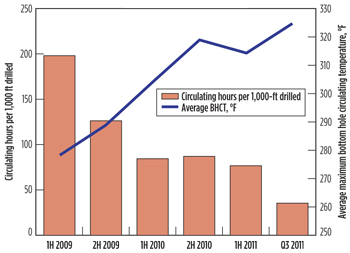
While the implementation of the above-mentioned processes resulted in a reduction in failure rate, they also enabled considerable performance improvements. Significant improvements in rate of penetration (ROP) have been achieved by implementing underbalanced drilling techniques (Billa et al. 2011). While in 2009, it was not uncommon to drill only 600 ft/day, it is fairly common to drill over 1,100 ft/day in 2011, necessitating faster decision making. Utilization of a Drilling Automation in Real Time Center, that integrates directional drilling with geosteering, has helped to leverage knowledge and further optimize performance. The team chose to track the number of circulating hours per 1,000 ft drilled as a measure of drilling performance in a harsh environment. Figure 2 illustrates that over the past thirty months, the number of circulating hours per 1,000 ft drilled have decreased by over 80%, while maximum BHCT has increased by over 45°F.
 |
| Fig. 2. Circulating hours per 1,000 ft drilled, despite BHCT increase. |
|
 |
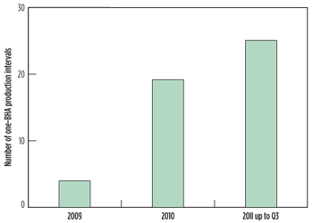
| Fig. 3. One-BHA production intervals (curve and lateral) increased over time. |
|
Single-BHA runs can only be achieved if there are no directional tool failures. Figure 3 illustrates how a systematic approach to improving tool reliability has resulted in an increasing number of one-BHA runs. Consequently, the team successfully delivered 25 one-BHA curve-and-laterals by September 2011. 
ACKNOWLEDGEMENTS
The authors would thank Shell Exploration and Production Company and Halliburton Energy Services for supporting the publication of this article. The authors would also like to thank David Braquet, David Genest, Toby Dauphinet, Eric Singleton and Brad McClurg from Halliburton Energy Services, Shabib Kadri from TH Hill Associates, and Robert Bennett from Shell Exploration and Production Company for their contributions. This article was adapted from 2012 IADC/SPE 151175 Drilling Conference paper held in San Diego, California, USA, March 6-8, 2012.
REFERENCES
1. Anderson, E. G., 1979. Basic Mesozoic Study in Louisiana, the North Coastal Region, and the Gulf Basin, Folio Series no. 3, Louisiana Geological Survey, Baton Rouge, Louisiana. 58 sheets.
2. Billa, R., J. Mota and B. Schneider, M. Weissman, “Drilling performance improvement in the Haynesville shale,” IADC/SPE paper 139842-MS presented at the IADC/SPE Drilling Conference and Exhibition, Amsterdam, The Netherlands, 1–3 March, 2011.
3. Eversull, L.G., Regional Cross Sections, North Louisiana, Folio Series no. 7. Louisiana Geological Survey, Baton Rouge, Louisiana. 10 sheets, 1984.
4. Hammes, U. 2009, “Sequence stratigraphy and core facies of the Haynesville Mudstone,” East Texas: Gulf Coast Association of Geological Societies Transactions, v. 59, p. 321-324.
5. Hubbard, B.L., S. J. Kadri, M. J. Crotinger, J. E. Griffith, J.E., and E. van Oort, “Nonproductive time (NPT) reduction delivered through effective failure investigations,” IADC/SPE 128425 paper presented at the IADC/SPE Drilling Conference and Exhibition, New Orleans, Louisiana, USA, Feb. 2-4, 2010.
6. Kaiser, M.J. and Y. Yu, “Haynesville shale well performance and development potential, Natural Resources Research, 2011.
|
The author
JOSE MOTA is onshore well engineering for Shell in the Americas. Mr. Mota graduated from UC Berkeley in 1996 with a MS degree in Petroleum Engineering. He joined Shell upon graduation, and has worked in in drilling operations in the U.S., Venezuela and The Netherlands.
JEFFREY GRABLE has over 30 years of oil industry experience with Halliburton, having started his career as a field engineer and progressed to become the global account manager for Shell. He received a BS degree in geology with minor in biology and computer science Ball State University, Muncie, Indiana.
DAVID WARD is a service coordinator for Halliburton for the Gulf of Mexico region. Mr. Ward obtained a BS degree in computer engineering technology from Prairie View A&M University in 2003 and went on to earn a MS degree engineering with a major in computer and communications engineering from San Francisco State University in 2005. |
|


