DANIEL SCHLOSSER and L. LAUN, NCS Oilfield Services; and CRAIG LANE, Tundra Oil & Gas
 |
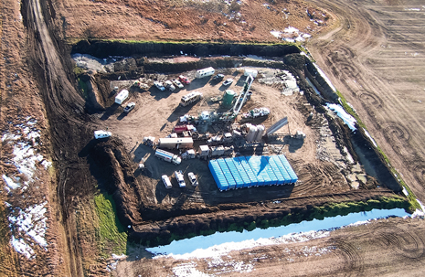
| Multistage frac job by NCS Energy Services under way at a Bakken well, in the province of Manitoba. Photo courtesy of Tundra Oil & Gas. |
|
With increased hydraulic fracturing activity, more fluid is hauled to the wellsite, pumped into fracturing operations, produced back to the surface and finally hauled to a disposal facility.
The public perception of the fracturing process is typically not based on facts, but rather on what they see and hear.
Reducing the amount of fluid required to complete a well not only reduces traffic on the roads, but it also reduces costs for the entire completion of the well. Reduced traffic, fewer tanks on location, and reduced time that the fracturing equipment is on location should improve public perception of fracturing operations.
In certain areas, there has been a move to increase the number of frac stages in each wellbore and decrease the size of each frac. This is because of reduced spacing between frac stages, as well as horizontal sections of the wells increasing in length. Typically, when operators increase the number of stages, the time required to complete the fracturing process increases, as does the total fluid requirement, due mainly to the pad and flush volumes for each stage.
BACKGROUND
Currently, the most common horizontal fracturing completion systems are plug & perf, ball-drop frac sleeve with external casing packers, cemented liners with burst ports, or perforated. When used in conjunction with CT fracturing, cemented and uncemented liners with annular fracturing systems (mechanical isolation, sand perforate & frac, or mechanical isolation and frac sleeves), they offer unique opportunities for reducing fluid requirements. Each of these systems has pros and cons, for each area of its deployment. The best system for any area (assuming a consistant frac design) is one that offers reduced frac time, lower fluid volumes, reduced costs, and contingencies for when the fracturing treatment does not go as planned.
Coiled tubing frac/sliding sleeve description. CT sliding sleeves are run as part of the casing or liner-string, and are either cemented into place, or in conjunction with external casing packers. The sleeves have the same ID as the casing-string, so no restrictions are added to the wellbore. There is no limit to the number of sleeves that can be run in a completion.
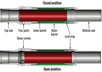
The sleeve used in this study (Fig. 1) was made up of only four major components: top and bottom subs, inner barrel and outer barrel. The inner barrel is made up of the same size and weight casing as run in the well.
 |
| Fig. 1. The sliding sleeve used in this study has four major components. |
|
To operate the sleeve, an isolation packer assembly is run and set in the sleeve. The wellbore is then pressured up, to supply a downward force on the BHA. This shifts the inner barrel down and exposes the frac ports.
Isolation packer assembly. The isolation packer assembly is typically deployed on CT, and is a modified, continuous-J, compression-set packer assembly, with a mechanical sleeve locator below the packer, to ensure depth control. Above the packer, the BHA contains an equalizing valve, abrasive perforator, frac port, centralizer and CT connector.
If there is a frac sleeve placed for the first zone, a compressible fluid below the packer is necessary, or a flow path, by which fluid can be displaced from the area below the packer. This is often accomplished through the deployment of a decompression sub at the bottom of the BHA, to give the fluid in the wellbore a flow path, while the sleeve is shifting downward in the wellbore. If the first zone is not initiated via a frac sleeve (burst port, abrasive perforated, etc.), the decompression sub is not required.
Horizontal multi-stage fracturing methods. The plug & perf completion method is used in cased wellbores. The first zone is perforated with a TCP gun, and the frac placed down the casing. A wireline, bridge plug and perforating assembly is then pumped into the wellbore, and the bridge plug is set below the next perforating interval. The tools are pulled up, the next interval is perforated (typically multiple sets of perfs), and wireline is pulled from the well. A frac is then placed in the newly perforated zone. This procedure is repeated up the wellbore. Once all zones have been treated, the bridge plugs are milled out, typically with CT.
This completion technique uses a considerable volume of water, because the wireline tools need to be pumped down to the perf interval, and the frac is placed down the casing, so a wellbore volume of fluid is injected into the formation ahead of each pad. If multiple sets of perforations are used per interval, it is impossible to know where the frac and sand is placed, possibly leaving reserves behind. This method requires multiple runs into the wellbore, with CT (perforating zone 1, milling the bridge plugs), and is very time-consuming.
Ball-drop frac sleeve completions are used more widely, because they can be used with high-rate and low-rate fracs. Ball seats are run between external casing packers, with seat sizes increasing in diameter, from the toe to the heel. A burst port is run for the lowest zone. During fracturing operations, the first frac sand is pumped, followed by a fluid spacer. A ball is dropped in the spacer fluid and pumped down the well. The ball will lodge in the corresponding ball seat and seal off the well. A pressure-increase forces the ball seat down, opening the port and the next frac is placed. This system has a limited number of stages that can be installed into a wellbore because of the limited seat sizes available.
Ball-drop frac sleeve completions are expensive to install, due to all the external casing packers required. In case of screen-outs, a CT clean-out can be complicated and difficult, because of all the restrictions placed inside the wellbore.
Another completion technology is cementing a liner assembly into a well. The liner can incorporate burst assemblies, or can be pre-perforated with TCP guns. CT is run into the well with straddle tools. The first burst assembly and set of perforations is straddled, and the fracture treatment is placed down the CT. This method is designed for reduced-rate treatments. With this method, the flush fluid is squeezed ahead of the fracture treatment, prior to the pad reaching the formation.
Another popular method for cemented and uncemented liners is mechanical isolation, conveyed on CT and abrasive perforating or with frac sleeves, and fracturing down the annulus of the CT and casing. The CT reduces wellbore volume, which reduces the amount of fluid that is squeezed ahead of the frac. The CT is in the well, so in the case of a screen-out, the sand can be circulated out of the well by pumping down the CT.
This method can accommodate low-to-medium-rate fracture treatments, depending on completion and CT sizes. Once all fracturing operations are completed, the wellbore is left full drift, without milling operations.
Coiled tubing fracturing with frac sleeve (half-straddle) procedure. An optimized method for completing multi-stage fracturing operations was created by combining the best features from the above methods into one system. This system has the advantages of fluid savings seen with fracturing down CT, the circulation options seen with annular fracturing (including being able to circulate the frac down to the BHA), and the ability to apply abrasive perforation to any zone, while leaving the wellbore for drift ID.
The first stage of this system occurs with the running of the sleeves as part of the final completion. If the sleeves are being used in conjunction with external casing packers, the frac sleeves typically replace the ball-operated sleeves’ locations.
The majority of the sleeves deployed, to date, have been cemented into the well. This allows the operator to know exactly where the fracture is initiating, thus ensuring proper drainage of the reservoir. The cementing procedure remains the same as the typical cementing procedure, since the sleeves cannot open during cementing operations. Aside from physical space, there is no limit to the number of frac sleeves that can be installed in a well.
During hydraulic fracturing operations, the BHA is connected to the CT and is run in to the bottom of the well. To reduce frac standby costs, the frac crew typically arrives on site, once CT is on bottom, and the tool is pressure-tested.
The frac sleeve is located using a mechanical sleeve-locator, and the packer is set in the frac sleeve. The well is quickly pressure tested, to ensure the integrity of the wellbore, and the well is pressured up to a shifting pressure of 1,450-1,750 psi differential pressure, to shift the sleeve open. A shift signature, seen on surface, via the CT weight, indicates the sleeve has opened, as well as a pressure bleed-off in the annulus.
Once the frac sleeve is open, the first frac is then circulated down the CT, with the annulus open. The return fluid is stored in a separate tank and will be used for flushing the frac. With the pad of the frac at the BHA (or acid spearhead, if used), the annulus is shut in, and the frac is pumped into the zone.
With the frac completely flushed into the zone, CT pulls up on the tool, which opens the equalization valve. Continuing to pull on the tool releases it. Then the tool is pulled up to the next location. Using the mechanical sleeve-locator, the next sleeve is located, and the tool set in the sleeve.
This process is repeated for the remaining sleeves in the well. With all zones completed, the CT and BHA are retrieved from the well, leaving a full-ID completion behind.
If perforating another zone between two sleeves is required, a ball is simply pumped down to the BHA and landed in the top of the frac port, isolating off the perforator. The perforations are cut, and the ball is reverse-circulated back to the surface.
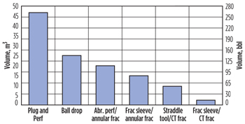
Fig. 2 shows a comparison of the minimum, per-stage, combined pad and flush volumes, for the different completion methods used in the southeastern Saskatchewan area of the Bakken. This chart assumes 5.5 in. casing, 2.0 in. CT and a frac depth of 6,562 ft.
 |
| Fig. 2. Minimum, combined pad and flush volumes for various fracturing methods. |
|
The Bakken formation in this area does not require a large pad to successfully place fracs; ideal pad volumes are typically less than 13 bbl. Pad volumes above 13 bbl consume unrequired fluid, which is pumped into the formation, increasing the frac height (which is undesirable, due to a water-bearing formation located above the Bakken). This increases the water volume required for fracturing, and ultimately increases operation costs.
Using CT fracturing, in conjunction with frac sleeves, lowers total fracturing fluid volumes by as much as 50%, compared to a ball-drop system, and 30% compared to annular fracturing using frac sleeves. This depends on frac design (pad requirement, sand tonnage and concentration, etc.) for the particular area. Pump time of the fracture treatments and the frac chemical volume also decreases with the reduced fluid volumes (Table 1), allowing for a significant cost-reduction. The plug & perf method of multizone-fracturing is not commonly used in this area, due to the large amounts of fluid required, and the costs associated with this technique.
| Table 1. Frac sleeve & CT frac (half-straddle) sand schedule per stage. |
|

|
Aside from the operational costs of hauling; fracturing chemical additives; and storing and disposing of the additional fluid volume, there is a social cost to using this extra fluid. Residents of the area see the large storage tanks on the wellsite; notice trucks traveling up and down their roads; hauling the fluid into location; and witness the large frac crew pumping the fluid down into the well, in a short amount of time.
With fresh water supplies becoming increasingly scrutinized and monitored, reducing the amount of water pumped into the ground to produce oil and gas has also become increasingly important. With fewer water trucks hauling water down local roads, not only is it safer for the residents, but the operations are less likely to impact the residents’ lives in a negative manner, by conserving this vital, natural resource.
EXAMPLE WELL
Below is a sample well, in the Bakken formation, in southwestern Manitoba, Canada. The well has the following parameters:
- Measured depth of 7,874 ft
- True vertical depth of 3,445 ft
- Casing: 5.5 in., 15.5 lb/ft
- CT: 27/8 in., 0.190 in. WT; length 8,859 ft,
- volume 53.5 bbl
- 29 frac stages
- The parameters for the frac treatment are:
- Rate of 5.7 bbl/min
- Water frac fluid, linear pads, cross-linked sand stages
- 5 tonnes of 20/40 sand
If we compare the total volumes of the 29 stages, for the different methods commonly used in the area (Table 2), one can see why the area shifted from using the ball-drop frac sleeves, through the different methods, ending up with the frac sleeve and CT method. The change from the ball-drop system to the abrasive perforation, with annular frac, was also driven by the significant completion cost reduction, of going from external casing packers, to a cemented system.
| Table 2. Fluid and sands summary for 29 frac stages. |
|

|
The shift from an abrasive perf with annular frac, to frac sleeves with annular frac, saw a significant time savings for fracturing operations, as it eliminated the perforating stage, saving 25 to 35 min. per stage. There is also a fluid savings of not having to pump the perforating fluid. If perforating fluid is not circulating, more of the flush can be used as pad for the next zone.
The change from frac sleeves with annular frac, to straddle tool with CT frac, saw fluid savings and a minor time reduction. Contingencies for sand-offs are limited, as the sand could only be reverse-circulated from the wellbore. All fluid inside the CT must be squeezed into the zone, ahead of the frac.
The process of CT fracturing, using frac sleeves, saw a large fluid savings and a significant time savings, as well. The cost savings of using a lower volume and quicker pump time were increased above the fluid cost, since the time to pump a 29+ stage frac was now less than 24 hr. This meant one less crew shift for everyone on site.
CASE STUDY: 21 WELLS
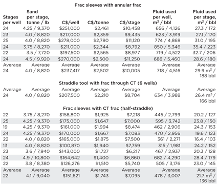
Table 3 shows a comparison of 21 wells, which were completed using frac sleeves with annular frac, straddle tool with CT frac, and frac sleeves with CT frac methods. The fluid volume is the total volume that was used in fracturing operations, including any circulation cleanouts, etc.
| Table 3. Comparative costs for different fracing methods. |

|
The frac ticket cost reduction generated by the frac sleeves with CT Frac method, compared to the frac sleeves with annular frac method, is $2,910 per stage, for a reduction of 29.1%. The same methods comparison shows a fluid volume reduction of 8.2 m3 per stage, for a 27.4% fluid reduction.
The frac sleeves with CT frac method, when compared to the straddle tool with CT frac method, shows a frac ticket cost reduction of $1,609 per stage, which equates to 18.5%. The corresponding fluid volume reduction for the comparison of these two methods is 4.7 m3 per stage, or a 17.8% reduction in fluid volume.
For a 24-stage wellbore, the frac sleeve with CT frac method saves $70,000 in frac ticket costs, and 1,258 bbl of fluid, when compared to frac sleeves with annular frac. The fluid volume equates to approximately seven truckloads of fluid brought to the wellsite, with additional reduction in trucking for the fluid leaving location. There are cost savings associated with the lower truck traffic, and less tankage onsite, which are in addition to the frac ticket savings.
CONCLUSION
Using the frac sleeve with CT frac (half-straddle) method, to place multi-stage fracture treatments in horizontal wellbores, lowers completion costs significantly, lowers water usage for fracturing operations, and enhances the public image of oil and gas operations. This method is the environmentally-conscious way to do multi-stage fracturing, where design allows. 
This article was adapted from SPE Paper 163935.
ACKNOWLEDGEMENT
The authors would like to thank Tundra Oil and Gas and NCS Oilfield Services for their permission to publish this article.
|


