ROBERT ZUBRIN, THOMAS HENSHAW, JIM SIEBARTH, BORIS NIZAMOV, COLIN APKE, and MARK BERGGREN; Pioneer Astronautics
Many small producers cannot apply enhanced oil recovery (EOR) technology, due to high capital costs resulting from site remoteness, limited pipeline access and long construction lead-times. To serve the small producer needs, Pioneer Astronautics is developing modular and portable biomass-based steam reforming technology, to create on-site CO2 for EOR and H2 for carbon-free electricity generation. The Pioneer Astronautics technology, developed with support from the Research Partnership for Secure Energy America (RPSEA) and Pioneer Energy, will allow small producers to have access to CO2 for enhanced oil recovery in a timely, scalable, locally field deployable, and cost effective manner. The technology will also produce clean electrical power, to offset producer capital and operating costs. To verify the concept, Pioneer Astronautics has designed, built and tested a modular pilot scale reformer unit, which delivers high yields of CO2 (> 35 vol. %) and H2 (> 50 vol. %) at total flow of 6,000 standard liters per minute (300,000) and 10 bar (150 psi). Using truck mobile technology demonstrated by Pioneer Energy, this high pressure gas can be readily separated into CO2 and hydrogen on site, enabling EOR operations at small producer sites nearly anywhere.
The United States has the oldest oil industry in the world. We invented the industry in 1859, and led its exponential worldwide growth from that point. As late as World War II, the USA alone produced more than twice the oil as the entire rest of the world put together—a factor which played a major role in securing the Allied victory—and continued to lead world petroleum production until the late 20th Century. Even today, we still rank in the top three.
As a result of this history, the United States now possesses hundreds of thousands of defunct or near-dead oil wells. However, these wells are not actually exhausted. About half the oil that they ever contained is still there, and nearly half of this, a resource amounting to hundreds of billions of barrels, could potentially be obtained using enhanced oil recovery (EOR).
Enhanced oil recovery using CO2 injection into the ground is a well-known technique that allows a typical well to increase its overall yield by as much as 40%. However, as currently practiced, EOR requires pipelines to deliver CO2 from natural reservoirs to oil fields. This technique is only practical for oil fields within limited distance from such reservoirs, as the capital cost of building pipelines over long distances is prohibitive. In general, such pipelines only serve major oilfield customers as the return from EOR from isolated small fields is insufficient to justify the capital cost of pipeline construction, and small producers typically do not have the cash to pay for such construction. In addition, pipeline CO2 is only available in very few regions of the country, which possess natural CO2 reservoirs.
Figure 1 compares the location of current CO2 pipelines and the largest stripper well producing states. It can be readily seen that pipeline CO2 is simply unavailable across the vast majority of the nation, and particularly absent from those states containing the vast majority of small producers. Even in those states that have pipeline CO2, it is generally impractical to build pipelines to remote stripper well sites, as the return from CO2-EOR from isolated small fields is insufficient to justify the capital-cost of pipeline construction.
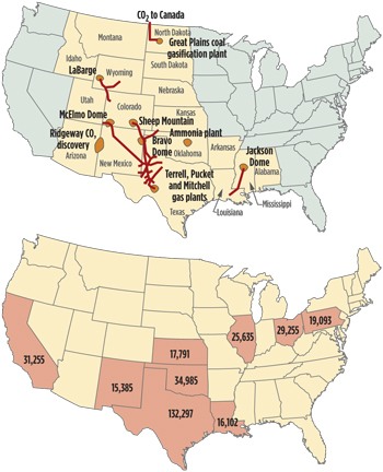 |
| Fig. 1. A comparison of current CO2 pipelines (top) and top stripper well producer states (bottom). |
The idea of using the exhaust from fossil-fuel fired power plants for EOR has been widely discussed. However, the electrical industry, for reasons of economies of scale, has based itself primarily on large (500 MWe to 1000 MWe) central power stations, located near their primary metropolitan markets. In general, therefore, such plants will not be located on the site of oil fields, and certainly not chosen to meet the needs a small producer. In addition, flue gases from conventional fossil power plants typically contain relatively low (<15%) CO2 concentrations, and exhaust it at atmospheric pressure, factors which make it difficult to economically separate for use in EOR. As a result, such stations offer little potential utility for supporting EOR for anyone, and are particularly useless for small producers.
What is needed is a system that can deliver CO2 directly to small producers, wherever they may be, without major capital expenditures, in a timely fashion, after a decision has been made to undertake EOR, on a scale relevant for small-field operations.
THE PIONEER APPROACH
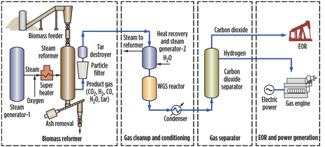 |
| Fig. 2. Simplified process diagram of the Green Oil EOR-CO2 system for small oil producers. |
To meet this unmet need, Pioneer Astronautics is developing a modular, truck-portable renewable energy system for CO2-EOR called Green Oil (Fig. 2). The Green Oil technology, or GO for short, works through the steam-oxygen reforming of biomass into CO2 and hydrogen. This is followed by product gas cleanup, conditioning, CO2-H2 enrichment and gas separation. The system simultaneously generates CO2 for on-site well flooding and H2 for carbon-free electrical power, for local or grid use. It is designed to generate 1 MMcf of CO2 per day, for the recovery of about 100 bopd. The hydrogen produced is capable of generating about two megawatts of carbon-free electricity. This power can be used locally or sold to the local grid, to reduce capital and operating expenses. In contrast to approaches involving the construction of pipeline, large power plants, or other mega projects which typically take many years, the transportable Pioneer Astronautic system can go directly to the small producer fields where it is needed, and do so in a timely manner. As an additional advantage, the system sequesters more biomass-derived carbon than is released by the burning of the oil it yields, and thus produces both carbon-free electricity and carbon-free oil.
The GO system is made up of four primary system components: biomass reformer, gas cleanup and conditioning, gas separator, and gas turbine electrical generation system (Fig. 2). The biomass reformer is based on the design legacy of the Imbert downdraft gasifier to minimize the production of tar by-products, flexible fuel turn-down, and low sensitivity to slag formation. However, its unique design is tailored to produce clean, high pressure (> 10 bar), high concentrations of CO2 for on-site well flooding and H2 for electrical power for the small producer. It uses oxygen (not air) and steam for higher product yields and reactor temperature control. The use of oxygen beneficially results in heating a smaller gas volume, operation of smaller process equipment, and reduced NOx generation. The Pioneer device also uses a water gas shift reactor to enrich the CO2 and H2 yield, by catalytically converting residual CO and water to high concentration CO2 (>35%) and H2 (>50%) in the gas stream. Since the Pioneer device generates high CO2 concentrations at high pressure, separation and compression energy and cost issues typically encountered with low pressure, low concentration CO2 from fossil fuel combustion power plants is greatly reduced. To separate the CO2 from H2, the GO system uses a methanol-based temperature swing approach, developed as a truck-portable unit, by our allied company Pioneer Energy. In previous testing, the separator has been demonstrated to operate with over 95% CO2 separation efficiency.
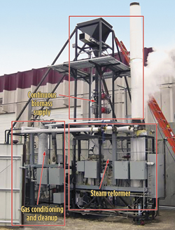 |
| Fig. 3. Photograph of the Pioneer Astronautics’ pilot-scale Green Oil reformer test rig with various test sections identified. |
 |
|
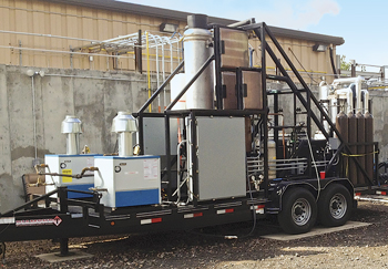
Fig. 4. The Pioneer Energy truck-portable CO2/H2 separation unit.
|
A photograph of the GO test system is shown in Fig 3. A photograph of Pioneer Energy mobile CO2/H2 separation unit is shown in Fig. 4.
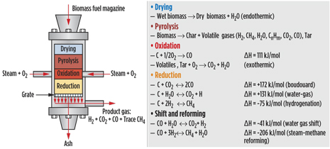
The gasifier is the heart of the GO process, so its operation is discussed in some detail here. Gasification is the partial or incomplete oxidation of carbonaceous material into a useful product or material, such as syngas, commercial fuels or chemicals. In the GO system, a steam-oxygen gasification agent is used to generate CO2 for EOR and H2 for electricity generation. Steam gasification generates a significantly different product distribution than air gasification. For example, the H2 content can be greater than 50 vol. % with steam, as compared to a typical value of 15 vol. % with air. However, steam gasification is endothermic and thus requires a heat source to generate product gas. This is achieved by simultaneously adding oxygen to the steam flow, to induce exothermic oxidation of the biomass, to supply the necessary heat. In doing so, one can adjust the steam, oxygen and biomass feed ratios to optimize the CO2 and H2 gas yields.
 |
|
Fig. 5. Left: Diagram of downdraft gasifier and reaction zones. Right: Some of the key chemical reactions occurring in the various gasifier zones.
|
The gasification is performed in a downdraft configuration in which both the gasification medium and biomass flow down together in the same direction (Fig. 5). Here the biomass is fed from the top, and the steam-oxygen mixture enters the reactor from the side, with the product gas exiting from the bottom. As the gas and biomass flow down into the gasifier, several characteristic reactions zones set up inside the bed. These include the drying, pyrolysis, oxidation (combustion) and reduction zones as illustrated in Fig. 5.
In the GO system, the pyrolysis, oxidation and reduction zone temperatures are observed at approximately 600oC, 1000oC, and 700oC, respectively. Within each zone, numerous reactions occur, with the overall result of generating a product gas composed primarily of CO2, H2 and H2O, with smaller amounts of CO and CH4. Some of the more important reactions are listed in Fig. 5. Since the drying, pyrolysis and reduction reactions are endothermic; the energy to perform these reaction steps is derived from the exothermic reactions in the oxidation zone. The key performance feature of the downdraft gasifier is that the pyrolysis products, especially the tars, are passed through the high temperature oxidation zone, where additional tar decomposition occurs. This allows the product gas to be generated with low tar content, so as to minimize the operational impact on downstream machinery.
Another key feature of the gasifier is the grate, which performs several important operations during gasification. The grate supports the biomass bed while passing product gas downstream. It also continuously removes char and ash byproducts to an ash bin. This prevents excessive particle buildup and possible over-pressurization of the gasifier bed. In the GO gasifier, a rotating grate is used that stirs the bed and prevents the biomass from bridging and channeling, which could lead to fuel flow stoppage and excessive reaction temperatures.
The gasification begins with the generation of steam from a conventional tube boiler, steam generator-1. The steam is then combined with oxygen and flowed into the super heater unit. During start up, a small amount of hydrogen is added to the flow here, allowing the oxygen/steam mixture to be heated up to 650oC. The superheated steam-oxygen mixture is then injected through a circular arrangement of seven nozzles, to rapidly ignite the biomass inside the reformer. Once ignition is achieved, the superheater hydrogen can be turned off, as the reaction becomes self-sustaining.
Biomass is fed into the reformer by way of a pressurized lock hopper system, using a high pressure, gas tight rotating valve assembly, which in turn is fed by a pneumatic conveyor that shuttles biomass from a dry storage bin to the hopper.
The oxygenated steam reacts with the biomass, yielding a large amount of product gas that exits the bottom of the gasifier and flows to a cyclone for removing entrained particles in the gas flow. To further reduce tars in the gas flow, a tar destruction reactor consisting of an olivine packed bed is used to catalytically destroy the tar. After the tar destruction reactor, the product gas is flowed to a heat recovery unit, steam generator-2, to generate auxiliary steam which is fed back into the reformer and reduces the steam load of steam generator-1. The product gases, H2, CO2, CO, H2O and CH4, is passed to a water gas shift reactor where the CO is reacted catalytically with steam to produce additional CO2 and H2. The product gas from the water gas shift reactor unit is sent to a condenser, where it is cooled down and water is removed before being sent to the H2/CO2 separator. The gas composition exiting the reformer and water gas shift reactor is monitored with gas chromatography (GC), for characterizing the gasification performance.
PERFORMANCE RESULTS TO DATE
To test this concept, Pioneer Astronautics designed and fabricated a fully-automated, continuously-fed, biomass-based pilot reformer unit under a research partnership with a Secure Energy for America (DOE) sponsored contract. Its construction is shown in Fig. 3. The system has operated at gas production rates up to 6,000 SLPM (300,000 cf/day) at 10 bar (150 psi) and, taken together with the Pioneer Energy gas separator system, contains all the unit operations of a portable CO2-EOR field unit. The device is modular and can be disassembled and mounted on a portable trailer for field testing.
 |
|
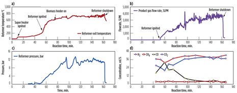
Fig. 6. A typical time history of the pilot scale GO system performance data. In the run shown, the system demonstrated over 4,000 SLPM product gas flowrate at 10 bar with >35% CO2 and H2 yield. (A): Reformer temperature. (B): Product gas flowrate. (C): System pressure. (D): Product gas composition using CO-shift catalyst.
|
To determine the GO device performance, a large number of tests were conducted over a wide range of operational conditions, using pine wood pellets as the biomass fuel. Several interrelated parameters affect the gasification efficiency, rate, and product distribution. Among these are the steam to oxygen ratio, oxygen feed rate, particle size, fuel moisture content, bed temperature, bed height and bed pressure. Figure 6 shows the typical time history of reformer temperature, product gas flow, system pressure, and product gas composition. Various reformer events such as the super heater and biomass ignition points, the initiation of the biomass lock-hopper feed supply, and the reformer shutdown are noted. In Fig. 6A, the biomass ignited at about 300oC as indicated by a sudden rise in the temperature as registered by thermocouples placed inside the reformer. As adjustments to the gas and solid fuel are made, the temperature steadily climbs and then plateaus at about 700oC. The 700oC gas temperature is typical of steam reforming of char form CO and H2. The excess heat in the gas stream is recovered in the secondary steam generator to produce an auxiliary steam flow, which is utilized in the gasifier. The system is presently able to recover about 50%–60% of primary steam flowrate. However, with process optimization, it is expected that nearly all the reformer steam flow can be generated from waste heat in the system.
Steady product gas outflow near 4,000 SLPM at 10 bar was demonstrated through adjustment in the steam and oxygen flowrates (Fig. 6B). A 4:1 steam-to-oxygen mole ratio was used to achieve this flowrate. On average, a gas yield of about 1.5 Nm3/kg of biomass was typically obtained in these experiments. With flow optimization, the GO unit has produced a product gas flowrate over 6,000 SLPM. Through adjustment of a back pressure control valve, the system pressure reached 10 bar (150 psi). The pressure drop from the reformer downstream to the back pressure control valve was small, on average ΔP < 0.5 atm., and indicates good gas throughput through the reformer and downstream units and piping.
| Table 1. Typical Green Oil Pilot Test Results |
|
.gif)
|
The compositional analysis of the product gas is determined by sampling a small gas slipstream and analyzing the constituents, by gas chromatography. The product gas was sampled downstream of the water gas shift reactor between the condenser and back-pressure control valve. A typical gas chromatograph analysis of the product gas stream is shown in Fig. 6D, which indicates high yields of carbon dioxide and hydrogen concentration, and high conversion of CO are obtained. Typically the CO conversion (removal) efficiency of the water gas shift reactor can be up to 90% of the inlet CO. With optimization of the reactor thermal control and gas flow conditions, the shift reactor can convert more than 99% of the CO in the flow. The process conditions and tests results for the GO system are summarized in Table 1.
SAMPLE SITE EVALUATION
 |
|
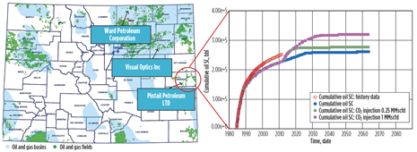
Fig. 7. Simulated cumulative oil production of Pintail’s wells in Grouse field, with and without two years of CO2 injection.
|
As part of the Green Oil program effort, oil wells in the four states of Colorado, Ohio, New Mexico and Kansas were evaluated by Petroleum Recovery Research Center (Socorro, NM) for applicability of the proposed technology. In Colorado, the PRRC researchers completed a comprehensive study including reservoir characterization, geomodel build-up and reservoir simulation. Fig. 7 shows modeling data for the cumulative oil recovery with and without CO2 injection after two years for the Grouse field reservoir, Cheyenne County, Colorado, belonging to the small producer, Pintail Petroleum Ltd. Pintail’s Grouse field Spergen reservoir was selected for the purpose of CO2 enhanced oil recovery because it contains a water injector and interconnected wells, as well as meeting all the necessary criteria for CO2 EOR. The reservoir performance with CO2 injection for two years (01/01/2012–12/01/2013) was simulated with a pseudo-miscible model (black oil model) for 50 years. The CO2 injection rates are set as 0.25 MMscf/day (5,107 tons/yr) and 1 MMscf/day (20,427 tons/yr), respectively. For 0.25 and 1 MMscf/day CO2 injection rates, 4.20 and 2.97 Mcf of CO2 was required for each incremental barrel of oil produced over the base case, respectively, which shows higher CO2 injection rate favoring economic recovery. At such rates of response, a GO system capable of producing 500 Mcf of CO2 per day could yield between 120 and 170 bopd, with a cumulative product value of about $5 million per year, at today’s prices.
FUTURE WORK
Together with Pioneer Energy, Pioneer Astronautics is continuing to develop the Green Oil system. Pioneer Energy is developing an oxygenated steam reformer that generates carbon dioxide and hydrogen from natural gas, while Pioneer Astronautics has begun to develop an oxygenated steam reformer that can utilize coal feedstock. These two approaches are complimentary, as natural gas offers the advantage of ease of use, while coal provides the cheapest potential feedstock. The latter is especially true in the Rockies, where very low cost coal is readily available. All three reformer systems—biomass, coal, or natural gas—can be readily mated to the same portable gas separation system, allowing EOR to go forward at both large and small producer oil wells anywhere in the country, using the most locally-advantageous feedstock. 
|


.gif)


