MEHMET FIDAN, HARDY NIELSEN and NEIL ANDERSON, ConocoPhillips; KRISTEN KOZLOWSKI, ADAM DONALD, PETER SHOTTON and JEROEN JOCKER, Schlumberger
Borehole sonic data are traditionally used for both geophysical calibration and geomechanical modeling. However, in a strongly layered medium, compressional and shear sonic waves propagate at different speeds, depending on the orientation of the wellbore relative to bedding. This phenomenon, known as elastic anisotropy, is especially common in shale formations, where constituent plate-shaped clay particles are often oriented parallel to one another. When shales exhibit a vertical axis of symmetry roughly orthogonal to layering, they can be described by a form of elastic anisotropy known as transverse isotropy (TI), Fig. 1.
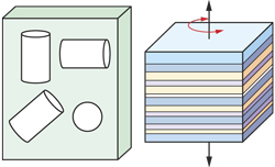 |
| Fig. 1. Homogeneous isotropic medium (left) and transverse isotropic medium with vertical axis of symmetry (right). |
|
Since transverse isotropic shales compose a major part of sedimentary rocks overlying hydrocarbon reservoirs, the need to characterize anisotropic properties is widespread. Failure to account for shale anisotropy can contribute to errors in seismic processing, amplitude variation with offset (AVO) analysis, and migration. Neglect of anisotropy can contribute to both fluid losses while drilling, and completion failures, primarily due to an incorrect, incomplete understanding of the Earth stress field, which depends strongly on anisotropic elastic properties of the encountered formations.
ConocoPhillips faced several geomechanical challenges in Eldfisk oil field, in the southern section of the North Sea, between Ekofisk and Valhall fields, Fig. 2. The field produces from the Ekofisk, Tor and Hod reservoirs, which are composed dominantly of high permeability, high-porosity chalk. The overburden in this area is composed mainly of anisotropic shale. Originally developed by pressure depletion, which has caused compaction of the reservoir and some settling of the seabed, Eldfisk field has experienced a number of wellbore stability issues in the overburden. High overburden pore pressure, combined with low reservoir pressure, has resulted in very narrow mud-weight windows through the intermediate hole section before entering the reservoir. In the lower portion of the shale, directly overlying the reservoir, fluid losses have been common while drilling, sometimes resulting in multiple sidetracks to land the casing.
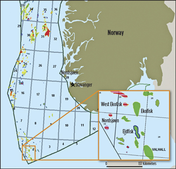 |
| Fig. 2. Location of Eldfisk field. Source: Norwegian Petroleum Directorate. |
|
Although traditional fracture gradient models were historically used to predict the safe upper bound mud weight, there was now a need to investigate alternative workflows, which accounted for variations in rock properties. In an effort to characterize the transverse isotropy of the shale in the overburden, ConocoPhillips engaged a team of Schlumberger consultants to conduct a study integrating single-well, borehole sonic data with relevant offset well data. Elastic stiffness coefficients derived from the workflow were used to compute an anisotropic, minimum horizontal stress profile along the wellbore that was more accurate than conventional pore pressure and fracture gradient modeling techniques that assume isotropic formation properties. As a result, the study helped to achieve a more reliable determination of the mud weight window to use while drilling through these anisotropic shale formations.
CHARACTERIZING TRANSVERSE ISOTROPY
Historically, wellbore stability models in overburden rocks have been defined by continuous fracture gradients computed as a function of pore pressure and overburden stress. However, this conventional methodology of stress modeling, Fig. 3, does not take into account variations in rock properties. They assume all rocks are homogeneously isotropic, i.e. that their properties are the same, regardless of the direction of measurement and that all lithology along the wellbore responds to the pore pressure and overburden stress in a similar manner, Fig. 1. In TI shales, when such isotropic models fail to match actual observations of wellbore stability (leak-off tests, formation integrity tests, drilling-induced features visible at borehole walls, etc), artificial boost factors, dynamic-to-static correlations, or unjustifiable tectonic strains must be applied to make them fit. The accuracy of these stress models is always questionable, due to large uncertainties in the input parameters.
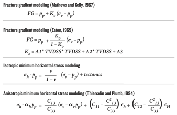 |
| Fig. 3. Traditional stress modeling equations, assuming isotropy (top/center). Anisotropic modeling equation used in this study (bottom). |
|
The best solution, therefore, is to use realistic, anisotropic elastic properties, which directly yield correct minimum horizontal stress profiles and, in turn, more reliable wellbore stability models. While Hooke’s law can be used to calculate stresses along the wellbore, elastic formation properties—contained in the stiffness tensor (C)—are required. To fully characterize transverse isotropy in horizontally layered shale formations, five independent elastic stiffness coefficients (C11, C13, C33, C44, and C66) are needed, a subset of which can be derived from borehole sonic measurements. Alternatively, the set of independent TI elastic properties can be composed of the three well-known Thomsen parameters, ε, δ and γ, in addition to the vertical compressional and shear velocities, VP0 and VS0, respectively.
The primary source of elastic wave propagation information are borehole sonic log data. However, due to the anisotropic character of these shales, the magnitudes of compressional and shear sonic velocities depend on the orientation of the well, relative to the TI symmetry axis of the formation, or relative dip. Thus, relative dip must be taken into account in anisotropic studies. When drilling through approximately horizontal shale beds, such as in Eldfisk field, the relative dip is equal to the well deviation. Most logged wells in the North Sea have been drilled from a central platform, so wellbores penetrate the overburden at many different angles. For this study, sonic data were acquired in an Eldfisk well with deviations ranging from 40° to 60°. Combining the bedding orientation from seismic, with well deviation and azimuth, yielded a relative dip on the order of 55°.
Single-well processing of sonic data from a vertical well drilled through a horizontal shale bed can provide three sonic slowness measurements, which can be readily associated with three of the five independent, elastic stiffness coefficients. Meanwhile, analysis of sonic data from a deviated hole drilled through a horizontal shale, such as the Eldfisk study well, increases the number of sonic slowness measurements that can be related to elastic formation properties from three to four. One of the most vital components needed to solve for anisotropy is the horizontally polarized, horizontally propagating shear, or Stoneley shear slowness. Conventional sonic tools are not fully characterized to understand the effect of the tool in the wellbore, nor do they consider the alteration around the wellbore to estimate the shear derived from the Stoneley in the cross-sectional plane.
For this study, therefore, Schlumberger’s Sonic Scanner technology was used to acquire very high-quality compressional, shear and Stoneley waveforms in the study well, since this tool is the only wireline tool currently available that is fully characterized for tool effects and alteration in the near-wellbore region. This was the first time that the operator had used this particular tool in the North Sea for advanced applications in geomechanics. Since even advanced sonic log analysis provides only a subset of the total measurements necessary to obtain all five TI elastic coefficients, compressional slowness data from several offset wells were also integrated for the study, as described below.
WORKFLOW APPLIED IN ELDFISK STUDY
Schlumberger consultants developed the following workflow, based on experience dealing with wellbore stability issues related to anisotropic shale formations elsewhere in the North Sea.
Validation of the TI assumption. The first step was to validate the assumption that the shale overlying the Eldfisk reservoir is, in fact, anisotropic. Based on a previous collaboration between Schlumberger and Phillips Petroleum by Aare and Knoth in 2002, regarding analysis of seismic data and sonic logs, the authors indicated that the overburden in this area described with a fair degree of accuracy as a TI anisotropic medium. Analysis of sonic dispersion curves from the Eldfisk overburden provided additional validation of the TI assumption. In particular, slowness-dispersion curves for the dipole flexural modes are parallel in nature, indicating that the shale here is TI anisotropic.
Single-well sonic processing and inversion. The second step was to perform a series of inversions on the Sonic Scanner data, to derive the initial three sonic slownesses (one compressional, two shear) and, finally, to solve for the Stoneley shear slowness using radial profiling algorithms. These algorithms take into account near-wellbore damage and dispersion effects to understand changes in slowness out into the formation. Inversion of the two shear slownesses, along with the Stoneley shear slowness, produced two coefficients (C44 and C66). With C44 and C66 determined, Thomsen’s shear anisotropy parameter, γ, can be readily calculated.
Integration with offset well data. The third step was to obtain the remaining three independent elastic stiffness coefficients necessary to characterize anisotropy in the Eldfisk area. To do so, compressional slowness data from several nearby offset wells, drilled at various relative dips, were integrated with shear slownesses from the single-well analysis using forward modeling. By plotting formation slowness as a function of relative dip, Fig. 4, and by adjusting the remaining two unknown Thomsen parameters, ε and δ, until the modeled curves fit slowness data points measured in the wells, it was possible to compute C11, C33 and C13 with reasonable accuracy.
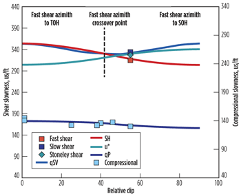 |
| Fig. 4. Formation slowness as a function of relative dip angle in the Eocene. Points = measured slowness data. Lines = phase slowness curves. |
|
Estimation of minimum horizontal stress. The ultimate goal of the workflow was to estimate the minimum horizontal stress, properly taking into account transverse isotropy of the overburden shale formation. First, the five independent elastic moduli derived from previous steps were converted from dynamic to static using correlations derived from core measurements. Then the anisotropic minimum horizontal stress was calculated using an equation by Thiercelin and Plumb for a horizontal shale subjected to gravitational loading, Fig. 3. This model was compared with two fracture gradients derived from conventional isotropic equations by Eaton, and Matthews & Kelly, Fig. 5. Both of these methods compute fracture gradients as a function of pore pressure and overburden stress, without accounting for changes in rock properties (stiffness or deformation).
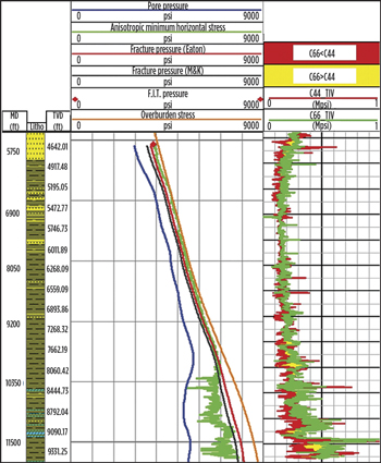 |
| Fig. 5. In upper section, anisotropic minimum horizontal stress (center/green) is similar to fracture gradients (red, black). In the deeper section, it is significantly lower. |
|
The minimum horizontal stress, based on the anisotropic equation, did not require the introduction of any artificial tectonic strains or boost factors to match the formation integrity test and mud weights used to drill the study well. However, the isotropic equations would have required corrections of up to 300 psi to match the observations. Overall, fracture gradient methods underestimated the minimum horizontal stress at shallower depths, and overestimated it in the deeper portion of the overburden directly over the Eldfisk reservoir, where fluid losses had been observed in offset wells. Indeed, the fracture gradient was significantly higher (500 - 600 psi) than the anisotropic minimum horizontal stress in this section. As a result, mud weights based on fracture gradient methods in the past had been higher than necessary, which was confirmed by drilling observations from offset wells on the platform. Anisotropic stress modeling yielded a more reliable determination of the mud weight window to use while drilling through these TI shales.
CONCLUSION
The workflow outlined above accurately estimates the elastic properties of transverse isotropic overburden shales using four slowness measurements from a single well, integrated with compressional slowness from multiple offset wells drilled at different relative dips through the same formations. Outputs of this workflow include five independent TI constants or, equivalently, the Thomsen parameters.
For seismic processing applications, taking anisotropy into account can improve NMO and dip-moveout corrections, AVO analysis and migration. In geomechanics, characterization of independent stiffness properties is an intermediate step toward applications, such as wellbore stability studies and hydraulic fracture design.
Based on this study, ConocoPhillips decided to utilize Sonic Scanner to extend the data coverage, and has adopted anisotropic modeling techniques to feed into assessing the mud weight windows of subsequent wells in Ekofisk and Eldfisk fields. Along with other operational changes, characterization of transverse isotropy is contributing to fewer wellbore stability issues, lower non-productive time and reduced costs. 
ACKNOWLEDGEMENT
The authors thank ConocoPhillips and Schlumberger management for permission to publish this work. This article is based on a paper presented at the SPWLA 52nd Annual Logging Symposium in Colorado Springs, CO, USA, May 14-18, 2011.
|
AUTHORS
|
| MEHMET FIDAN is a formation evaluation specialist for ConocoPhillips in Norway. He has 30-plus years of experience in the oil field, including seven years as a logging engineer with Schlumberger Wireline Services. Mr. Fidan received his bachelor’s degree in mechanical engineering from Middle East Technical University, Ankara, Turkey, and a master’s degree from The City University, London. |
|
| HARDY NIELSEN is a geoscience fellow for ConocoPhillips Norway, working in the Ekofisk area overburden characterization teams. Mr. Nielsen has 30 years of industry experience, 18 years of which have been with ConocoPhillips Norway, and the rest evenly split between GECO A/S and Mobil Exploration Norway. His current focus is on overburden mechanical characterization and 4D seismic monitoring of the cuttings re-injection in the Ekofisk area. Mr. Nielsen received a Cand. Scient degree in geophysics from Aarhus University in Denmark. He is a member of SEG and EAGE. |
|
| NEIL ANDERSON is a petrophysicist for ConocoPhillips in Norway. He has 21 years of experience in Norway, 15 of which were spent in Stavanger. Prior to his career with ConocoPhillips, Anderson worked as a field engineer and petrophysicist for Schlumberger, and as a petrophysicist for Norsk Hydro. He received his degree in engineering from the University of Saskatchewan, Saskatoon. |
|
| KRISTEN KOZLOWSKI is a senior petrophysicist for Schlumberger Data & Consulting Services (DCS). Her current area of focus is acoustics interpretation and petrophysics. Ms. Kozlowski joined the company in 2004 and, in 2006, she joined DCS to work in the geomechanics domain, focusing on acoustics and applications to stress modeling and completions. She received her bachelor’s degree in materials science and engineering from the University of Michigan. She is a member of SPWLA and the Norwegian Formation Evaluation Society. |
|
| ADAM DONALD is a principal acoustics and geomechanics engineer at Schlumberger and is the area domain leader covering Asia and Australia, based in Kuala Lumpur, Malaysia. Mr. Donald has 14 years of experience with Schlumberger, focusing on completions strategies for unconventional reservoirs, tight gas, natural fractures and conventional plays, as well as wellbore stability, rock mechanics testing, sanding and drilling optimization. He received his Bachelors in geological engineering from University of Waterloo in Ontario, and a Masters in mining engineering from Dalhousie University in Nova Scotia. |
|
| PETER SHOTTON is a geomechanics engineer with the Schlumberger Data & Consulting Services (DCS) geomechanics team in Aberdeen, Scotland. Mr. Shotton joined the company in 2006, and his current focus is wellbore stability modeling, real-time drilling geomechanics, and sonic applications to geomechanics. He received his bachelor’s degree in geoscience and a master’s degree in petroleum geoscience from the University of St. Andrews, Scotland. |
|
| JEROEN JOCKER is a senior petrophysicist working for Schlumberger Data & Consulting Services in The Hague, The Netherlands, from where he supports projects involving borehole acoustics in anisotropic media. He joined Schlumberger in 2006 as a research scientist specializing in borehole sonic and geomechanics, first working in Ridgefield, CT and later in Cambridge, MA. He has a master’s degree in petroleum engineering and a PhD in poro-elastic wave propagation, both from Delft UT, The Netherlands. |
|
|


