|
ANTONIO C. CAPELEIRO PINTO, GIOVANI C. NUNES, JÔNATAS RIBEIRO, SAULO T. C. LIMA, MARCELO C. SALOMÃO, LUIZ E. PECLAT and SERGIO D. LIBERA; Petrobras
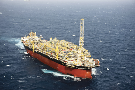 |
| The FPSO Cidade de Angrados Reis is an example of a recent FPSO built before the new, standardized design. |
|
The history of the Santos basin pre-salt formation is related to the separation of South America and Africa 120 million years ago. When the continents began to separate, a large rift was formed, whose direction was almost parallel to the Brazilian coast. The rift was initially filled with sedimentary rocks—sand, clay and igneous rocks. Over time, the rift increased its width and formed high-salinity lakes, where sandy and clay rocks were replaced by carbonate rocks associated with trapping, binding and cementation of sedimentary grains by microorganisms, especially cyanobacteria. This created structures known as stromatolites. The end of the deposition of carbonate rocks is associated with the onset of deposition of salt, caused by climate changes, forming a sealing layer for the hydrocarbons.
In 2001 and 2002, as operator of different consortia, Petrobras obtained, through two consecutive bidding processes promoted by the Brazilian regulatory agency, ANP, the concession to explore six blocks in Santos basin. Discoveries of hydrocarbon reservoirs followed—in 2006, the Parati structure in Block BM-S-10; and in 2007, the Tupi area in BM-S-11 (now Lula field). The next important discoveries were Carioca and Guará (BM-S-09), and Iracema and Iara (BM-S-11). In BM-S-11, Petrobras is the operator, with a working interest of 65%, partnering with BG E&P Brasil (25%) and Petrogal Brasil (10%). In BM-S-09, Petrobras is the operator (45%), with BG E&P Brasil (30%) and Repsol Sinopec Brasil (25%) as partners. These discoveries are part of the Santos basin pre-salt cluster (SBPSC, Fig. 1).
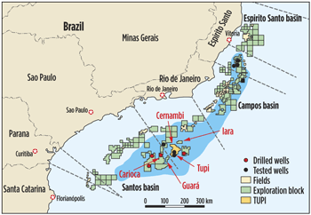 |
| Fig. 1. Fields in the Santos basin pre-salt cluster (SBPSC). |
|
In Lula field, the chartered FPSO, Cidade de Angra dos Reis, began producing in October 2010. It produces about 70,000 bopd through three wells. Associated gas in Lula has variable amounts (1-15%) of CO2, which is separated from the produced gas in the FPSO. The CO2-rich stream is reinjected in a gas injection well, and the specified gas is exported to shore. Two chartered FPSOs are performing extended well tests (EWTs) in the Santos basin pre-salt areas. Covering an area of about 11,600 sq km, 13 FPSOs (five chartered and eight owned by the consortia) have already been contracted for development of production in Blocks BM-S-09 and BM-S-11.
To enhance the local content share of infrastructure investments, as well as to accelerate the pre-salt development, the consortia for BM-S-09 and BM-S-11 decided to design and build eight similar FPSOs, known as “replicant FPSOs.” The first of these vessels will begin production in 2015.
RESERVOIR AND FLUID CHARACTERISTICS
The huge hydrocarbon volumes in pre-salt areas are placed in carbonate rocks of microbial origin, with vast extension and large thickness in most of the wells. The oil reservoirs are about 300 km offshore, in water depths as great as 2,300 m (7,546 ft). The sealing rock is a thick salt layer that reaches, in some places, 2,000 m (6,562 ft). The reservoir top is at depths greater than 5,000 m (16,404 ft), referenced to sea level. The API gravity is between 25 and 30, and the gas solubility ratio is in the 200-to-350/Sm3 range. The CO2 content is variable and, in Lula field, ranges from 1% to 15% (mol/mol), in the gas phase.
Similarities of the reservoir fluid characteristics allowed the use of identical topside facilities for most locations. Narrow variation in reservoir characteristics, such as pressure, temperature and fluid composition, resulted in similar conditions in flow from the wellbore to the FPSO, and in the process plant. Similarities among required pressures for gas and water injection allowed the use of the same FPSO project for different areas.
Reservoir drainage strategy. Considering the uncertainties involved in the exploitation of carbonate reservoirs, three EOR methods were chosen to develop the pre-salt fields—Water Injection (WI), Gas Injection (GI) and Water-Alternating-Gas Injection (WAG). The FPSOs were designed to operate with any production scheme, allowing the choice of which scheme will be used in each area at any time, changing it, if necessary, during the field’s productive life. For reservoirs not prone to the WAG method, just the CO2-rich stream will be reinjected.
CO2 reinjection or disposal. The BM-S-09 and BM-S-11 consortia decided not to vent the CO2 to be produced with the associated gas. Consequently, all the production units will have a CO2 removal plant.
FPSO CAPACITIES
The processing capacities of the standardized FPSOs were defined with consideration given to several parameters, such as power generation, deck space, load, maintainability, and others. The oil capacity is 150,000 bpd, gas capacity is 6.0 MMcmd, and water injection capacity is 180,000 bpd. The CO2 separation system allows CO2 content up to 40% at the maximum gas rate.
The gas plant is the most complex system in the FPSO, with more weight and requiring more footprint area. The maximum oil flowrate for each target area will depend on the GOR, so that the gas flowrate capacity is not exceeded.
Since differing productivities are expected for different well configurations and reservoir characteristics, the number of injectors and producers will be defined for each production unit to obtain the optimum economic results and hydrocarbon recovery. The riser balcony of the standard FPSOs has 63 slots.
SUBSEA EQUIPMENT
According to the schedule for developing pre-salt deposits, construction of the FPSOs is critical. They have to be designed before the drainage plan, subsea layout and equipment are completely defined. A new development plan by Petrobras, called Multifunctional Bell Mouth (MBM, Fig. 2), allows the design and building of the riser slots in the hull before the risers (flexible or rigid) and connection system (coupled or uncoupled) are defined. The MBM brings the flexibility to connect any size, inside the required range, and any riser type in the same slot.
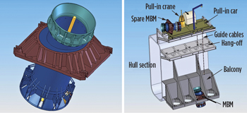 |
| Fig. 2. Multifunction Bell Mouth |
|
A wet Christmas Tree design was developed for pre-salt projects, suitable for production, gas or water injection, and WAG injection wells. The multiplex system for Christmas tree actuation allows an important simplification of topside facilities, since the subsea actuation modules will be installed subsea.
Gas pipeline. Petrobras defined, for the first route for gas export, a main, rigid gas pipeline with 24-in. ID. The FPSOs will be connected to this main pipeline through flexible lines and risers with 9.1-in. ID.
FPSO SYSTEMS
The FPSO processing plant comprises 16 modules, Fig. 3. The oil processing module includes oil separators, treater, heat exchangers and other equipment, designed to specify the produced oil according to market constraints. In the same way, the other 15 modules were designed to group equipment in accordance with each module’s purpose. Contracting the modules is done in packages. There will be a larger contract for the modules´ integration, that is, the integrator firm will be contracted to integrate the modules and install them in the FPSO topside. With this strategy, Petrobras is managing the contracts.
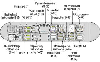 |
| Fig. 3. Modules on the FPSO topside plan view |
|
Hull. The same modules’ sizes and interfaces were defined for the eight FPSOs. Consequently, the FPSOs should have similar hulls. Instead of converting old ship hulls into FPSOs, Petrobras decided to build new hulls, in Rio Grande shipyard.
Oil transfer. The oil will be offloaded from the FPSO tanks to dynamic positioning (DP) shuttle tankers, connecting the FPSO sending station directly to the DP shuttle receiver station. This definition allows the use of the same offloading system for the eight FPSOs.
Riser balcony and manifolds. The purchasing strategy negotiated by Petrobras with manufacturers allows the riser balcony well sequence and topside manifolds to be defined in a later stage, when more information will be available.
Oil plant. The oil plant has one separation train, with three stages of separation. The first stage is a three-phase separator to separate oil, gas and water. Because of the high salinity in the formation water, this concept has a dilution water feed between two electrostatic treaters in series. The first electrostatic treater reduces water fraction to a lower level; after that, dilution water is mixed to reduce water salinity, to meet salinity and BSW specs.
Produced water plant. Produced water treatment has three steps: a skim vessel, hydrocyclones and a flotator. The skim vessel separates the oil segregated over the water surface. After that, hydrocyclones can reduce oil and grease content from about 1,000 mg/l to 200 mg/l. Polishing is made by a flotator that can specify oil and grease contents in treated water to less than 29 mg/l for overboard disposal, in accordance with regulations.
Seawater treatment and injection plant. Basically, seawater treatment, injected into the reservoir, comprises two main treatments, sulfate removal and oxygen removal or deaeretion. To reduce barium and strontium sulfate scaling potential in the reservoir, due to mixing of incompatible water, seawater will be desulfated before injection. This process is done upstream in the deaeretion step. Deaeretion reduces the corrosion rate by removing, from the injection water, the most corrosive agent (oxygen), in this case utilizing a vacuum process.
Utilities. Heating and cooling systems were designed to maximum possible load, meaning that many FPSO operational modes have been overdesigned. The main application of heating power, which is recovered from the power-generating gas turbines’ exhaust gases, is to treat the oil. The heating system design depends mainly on the petroleum flowrate, quality (viscosity and density), emulsified water fraction and salinity. The main application of the cooling system is the compression systems at the gas inlet or outlet. The gas from the three-phase separator has to be cooled down to 40ºC, before entering the main compression system. Additionally, gas cooling is required after each compression stage.
Gas plant. As mentioned before, CO2 will be separated from the gas stream and reinjected into the reservoir or disposed of in aquifers or depleted reservoirs. Internal evaluations showed that permeation through membranes was the best choice for the pre-salt application. The membrane process is simpler than amine absorption, and it can deal with a wide range of CO2, without any process parameter change. Membranes can specify a maximum CO2 content in export gas below the value required by ANP.
Upstream of the dew point control, the gas is dehydrated by molecular sieves, Fig. 4. This process was chosen instead of glycol absorption to avoid membrane damage. Another reason is that H2O molecules permeate easily through the membranes, causing water concentration, which could create hydrates in the CO2 stream, inside the wells. Basically, the gas plant can operate in two modes. In the first mode, the treated gas is exported, and the CO2 stream is reinjected. In the second mode, CO2 is not separated from produced gas (CO2 membranes in by-pass), and is reinjected with the hydrocarbon gas into the reservoir.
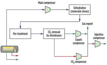 |
| Fig. 4. Gas treatment and compression scheme. |
|
Compression and generation. As explained previously, CO2 content varies among pre-salt areas and strongly affects the gas molecular weight. Therefore, the main compressors must deal with a wide range of molecular weights from different fields. Tthe export and injection compressors need to handle a significant molecular weight change, due to the two operational modes. That is achieved by means of a careful compressor design and by using speed variation (for all compressors), combined with suction throttling (for injection). Moreover, variable-speed-driven compressors help to save electrical energy.
IMPLEMENTATION
The FPSO standardization strategy is succeeding. Large equipment, such as compressors and power generators, was put out for bidding, and purchase contracts have been signed. While the FPSOs are in a more advanced stage, with the hulls and modules already under construction, other disciplines continue to evolve. Engineers continue to analyze whether there is any constraint to deploying the standard FPSO in any target area.
The advantages of this strategy will start to show up in 2015, when the first standardized FPSO is deployed. By 2017, it is expected that the strategy will be validated. 
ACKNOWLEDGMENTS
The authors would like to thank Petrobras and its partners in the SBPSC (BG E&P Brasil, Petrogal Brasil and Repsol Sinopec Brasil) for their permission to publish this article. In particular, we would like to acknowledge Antonio Carlos Capeleiro Pinto, Célio Vaz, Daniel Leite Lima and Marcel Eiki Katekawa, from Petrobras, who revised the manuscript.
|


