CLINT TODHUNTER and IAN CRANE, Xstrata; and JIM FOREMAN, MICHAEL FRANKLIN, JON HILL, JOHN PERRY and GREG MESZAROS, PathFinder, a Schlumberger company
Xstrata and PathFinder applied oilfield technology to construct a pattern of vertical and horizontal wells to degassify a coal mine in Australia. A custom extended reach drilling rig was built, and a mud motor used to drill horizontal laterals of about 12,000 ft at a depth of 500 ft. Pre-job modeling, automated surface rotational controls and MWD surveys reduced risk and improved drilling efficiency.
 |
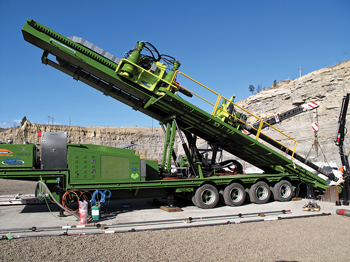
| Purpose-built ERD rig based on a rack-and-pinion design |
|
Extended reach drilling (ERD) technology, widely used for oilfield applications, is now being deployed in a large underground mine to drain methane gas, enabling safe, continuous coal extraction operations. A specially designed rig has been built to facilitate drilling these horizontal wells, which are at shallower depths than would be normal for oil or gas development. Integrated services deployed include an automated surface rotation control system, and real-time analysis of drilling and advanced ranging for accurate positioning of the bottomhole assembly (BHA). Horizontal wells have been drilled successfully and cost-effectively at a depth of about 500 ft and up to 12,000-ft TD, intersecting existing vertical wells as planned, and helping achieve coal production quotas.
BULGA MINING COMPLEX
Xstrata is a diversified mining group headquartered in Switzerland with operations and projects in 20 countries. Xstrata operates the Bulga coal mining complex, 110 mi north of Sydney in New South Wales, Australia. With an annual production of approximately 16 MMt, the Bulga Complex is one of the most prolific coal mining operations in the world. Five seams are targeted for underground extraction, one of which is the Blakefield Seam.
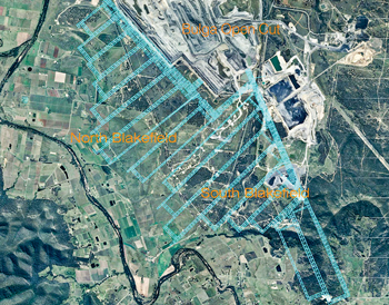
Longwall mining. The Blakefield South development (Fig. 1) uses the longwall mining method, whereby a wall of coal is mined in a single slice by a shearing machine that moves along the coalface, powered by a ruggedized rack-and-pinion system. The coal is then removed by a network of conveyor belts. A long row of hydraulic jacks aligned in parallel to the cutting face supports the roof behind the cutting machine and conveyor belt. As the shearer removes the coal, the powered roof supports move forward into the newly created cavity. The roof and overlying rock behind the longwall are allowed to collapse into the void behind—an area called the “goaf”—and pressure is reduced in beds above, sometimes leading to the release of dissolved gases. As mining progresses and the longwall shearer progresses through the seam, the area of the goaf increases.
 |
| Fig. 1. Blakefield South mine development |
|
Underground roads, known as “gates,” are driven to the back of each coal panel before longwall mining begins. The gate road along one side of the block is called the headgate, and the road on the other side is called the tailgate. These gates provide access to the longwall by mine workers and equipment, and a route for the conveyor belts carrying away the coal. Gates also provide the pathway for ventilating the mine. Fresh air travels up the main gate, across the coal face, and then down the tail gate. As it passes the longwall face, the air collects coal dust and gases, such as methane and carbon dioxide, that have been released from the coal. The volume and composition of these gases varies, depending on the chemistry and geology of the coal seams. Return air is extracted by ventilation fans mounted on the surface. Machines around the mine measure gas levels and, if they exceed pre-defined safe operating levels, signal for operations to be shut down. Effective ventilation is essential, not only to protect the health and safety of mine workers, but also to avoid non-productive time in a high-cost operating environment.
Blakefield South mine. Designed for an annual production of up to 8 MMt of coal, there are few larger underground developments in the world than the Blakefield South mine, and none with such high levels of gas. The high volumes of gas encountered are due not only to the chemistry of the Blakefield seam, but also to its multi-seamed geological setting. Many overlying seams are of poor quality or too thin to mine economically, but they lie close to those that are being extracted.
The Blakefield seam cutting face is approximately 10 ft high. The mine wall is 1,300 ft long and moves forward by up to 65 ft per day. As the shearing machine and associated roof supports move forward, collapse and pressure reduction in overlying strata typically extend to between 65 to 130 ft above the mine. The collapse above the goaf often produces horizontal laminations in the strata associated with local reduction in pressure, leading to methane coming out of solution in the overlying gas-saturated coal seams. The gas flows through the laminated zone to the areas of lowest pressure—which are most likely to exist within the mine workings—reaching a minimum in the tailgate.
It is not physically possible to remove the high volumes of methane using ventilators via the existing gate roads without creating an excessively strong wind and dust storm. The traditional method to augment mine ventilation systems, and deal with high levels of goaf gas, is to drill vertical wells to about 33 ft above the producing seam and then apply suction from the surface. This method is used commonly in Australia and the U.S. However, the coal being mined at Blakefield South not only has particularly high gas concentrations, but there are several pre-existing mine shafts above the current cutting face, which represent a challenge for drilling vertical wells on a sufficiently fine grid spacing. In addition, the mining area is in the Hunter Valley region of New South Wales. This is Australia’s premier wine growing district and a major tourist destination, so access is geographically limited, and there is pressure to keep surface equipment to a minimum. After a thorough review of alternative options, gas drainage experts at Xstrata decided that a combination of vertical and horizontal wells could provide a solution for effectively degassing the Blakefield South mine.
DEGASSING WITH HORIZONTAL WELLS
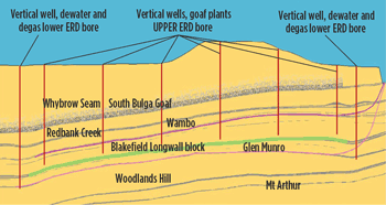
Xstrata developed a configuration of borehole designs that would best address the profile of the gas being produced in the laminated zones, Fig. 2. Horizontal wells at Blakefield South are typically about 2.25 mi long with TVD of just 500 ft. The rock strata exhibit some gentle folding with localized dips up to around 3°, which the wells must follow. Horizontal boreholes would provide connectivity to a large area of the gas producing zone, but the gas could not be effectively sucked out of the hole over the distances involved—in excess of 2 mi. Instead, the plan involved first drilling vertical holes into what would become the goaf zone, each with gas suction pumps at the surface.
 |
| Fig. 2. Vertical and horizontal well goaf gas drainage schematic |
|
Horizontal wells would then be drilled to intersect the vertical holes. Gas flowing into the horizontal wells would be sucked into, and then up and out of the nearest vertical hole. Effectively sucking large volumes of produced gas requires a large borehole. Horizontal hole sizes of 6 1/8 in. are typically used for degassing mines, but to meet the unusually high demands of Blakefield South, 12¼–in. holes would being required.
In very shallow horizontal wells, such as those planned for Blakefield South, there is little gravity slack-off weight—the weight-on-bit when entering the well—so additional mechanical push is needed. Most rigs used for drilling oilfield production wells are unsuitable for delivering the directional profiles required in shallow mining applications, so Xstrata built its own ERD rig based on a rack-and-pinion design, which enables it to both pull and push; utilizing thrust in addition to, or instead of, gravity.
Xstrata’s initial plans for drilling horizontal degassing wells indicated that a rotary steerable system might be required to achieve the necessary well trajectories. In late 2009, after detailed study of the drilling plan and leveraging previous horizontal drilling experience for gas drainage of laminated coals for Xstrata and other mining companies, PathFinder proposed that its directional drilling mud motors could deliver the well program at a lower operational cost while also avoiding the risk of losing expensive BHA equipment. The company was subsequently appointed as the drilling services provider, and quickly joined the team to prepare for operations.
Pre-job modeling. Thorough risk assessment, planning and modeling are required for all aspects of mining. The goaf wells must remain 100 ft from any mine workings; otherwise, they could cause flooding in a mine shaft.
The well construction plan, drillstring design and BHA design were optimized, based on proprietary pre-job modeling and analysis software. The Ideas integrated drillbit design platform takes into account various elements of the drilling system, including drill pipe, measurement-while-drilling (MWD) and logging-while-drilling (LWD) tools, reamers, stabilizers and steering systems. The software designs and tests bit behavior in a virtual well with actual drilling conditions to analyze the rock-cutter interface; BHA configuration; drillstring behavior and directional response; and operational parameters. The process quickly and efficiency results in optimized bits and reduced drilling risk.
The i-Drill engineered drilling system design uses predictive modeling to identify solutions that minimize vibrations and stick/slip during drilling operations, and optimize BHA performance for a given environment. Employing the Ideas integrated drillbit design platform, the system design quantifies the vibrations and rate of penetration (ROP) for a given drilling system as a function of time. This is accomplished by combining a bit-rock cutting model based on extensive laboratory testing with a finite element analysis of the bit and drillstring. As part of the design process, engineers simulate bit behavior, as well as each component of the BHA and the drillstring. Various combinations of drillbit options, drilling assembly components, drillstring designs, surface parameters, component placement and overbalance pressures can be examined. Such virtual testing of new technology and unconventional approaches eliminates the risk and expense of trial-and-error on the rig.
Automated surface rotation control. High torque, high drag and maintaining downhole toolface orientation were potential challenges while sliding with a non-rotating drillstring to make directional corrections in these complex, shallow, horizontal wells. The Slider automated surface rotation control system was deployed to increase the efficiency of the downhole mud motor and MWD directional system. The system works by imposing a rocking motion (oscillatory movements to the right and left) from the top drive during sliding operations, which results in the drillstring behaving largely the same during sliding as if it were rotating. Torque readings at surface, and sometimes downhole, are used as feedback to the computerized system that controls the rocking movement. The system enables the maximum amount of drag reduction while accurately controlling the downhole toolface. This is achieved without pulling the bit off bottom and greatly enhances ROP.
Drilling operations. The vertical wells were drilled first, followed by horizontal holes steered to pass as close to them as possible using standard inclination and azimuthal orientation devices in the BHA. Other MWD data acquired included dynamic measurement of pressure in the annulus to identify buildup of cuttings—a necessary task, as hole cleaning was difficult because the fresh water used as drilling fluid lacked viscosity.
Horizontal wells are started with a 17½-in bit, and the well is lined through the build section to the landing point, which is typically at 1,900 ft, TD. The 12¼-in lateral is left as an open hole. To date, there has been no evidence of hole collapse, although this risk is mitigated by the presence of the many vertical holes, which would continue to remove gas, even in the event of a localized collapse of the lateral. Hole stability was tested by chance when, while drilling the second lateral well in the program, a fire in the mine led to the rig being shut-in while pulling out of hole. When the BHA was tripped back into the well six months later, it encountered no blockages.
Intercepting vertical wells. Proprietary multi-station survey correction software was used to refine downhole MWD survey measurements and steer the horizontal well as accurately as possible to the vertical wells. Once within close vicinity of a target well, the RADAR real-time analysis of drilling and advanced ranging service was used to control steering. This service uses a passive magnetic ranging technique to detect interference at the BHA from a magnetic sonde lowered into a vertical hole, employing conventional MWD tools transmitting a magnetic field. Continuous, real-time measurements during drilling provide the distance and direction of the vertical well, together with 3D images and projections of the wells. Borehole trajectories can be accurately placed, with quality indicators improving confidence in the results. This service is typically used to avoid collision of wells drilled closely together, such as in steam-assisted gravity drainage (SAGD) applications. The opposite is the case for gas drainage applications, where the objective is to intercept vertical wells.
EXAMPLE WELL: GDL04
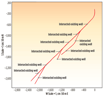
At time of writing, the project had been running for about 18 months, and the team had completed the fourth horizontal hole. Well GDL04 (Figs. 3 and 4) was typical of those being drilled. The purpose-built ERD rig, with 300-ton pull-down capacity, was anchored to a 500-ton concrete pad at 65° from vertical, and a 21-in conductor pipe, 40 ft long, was set at the same 65° angle. The 17½-in surface hole was drilled from the surface, building angle to 90° before landing in the target zone. After setting 13⅜-in casing, the lateral was drilled to 12,000 ft, MD, and 558 ft, TVD.
 |
| Fig. 3. Well GDL-04 sectional view |
|
 |
| Fig. 4. Well GDL-04 plan view |
|
The BHA incorporated a 12¼-in Smith Bits standard PDC bit, a PathFinder mud motor with 12-in stabilizer, a dynamic pressure module, and fixed-collar directional service. The automated surface rotation control system enhanced ROP and improved directional control while sliding the mud motor; and an agitator helped avoid pipe buckling and stick/slip. The real-time analysis of drilling and advanced ranging service provided the distance and direction to existing vertical wells, enabling steering and sidetracking of the lateral to intersect them as planned.
CONTINUOUS IMPROVEMENT
Building a pattern of vertical and horizontal gas ventilation wells was new to both Xstrata and PathFinder. The first two holes presented several learning opportunities, but by the third horizontal well, an effective process had been established that has delivered continuously improved efficiency with each subsequent well. The drill bits, BHA and other drilling equipment used have proved very durable. The mud motor achieved long run hours—typically between 400 and 500 hr—before requiring components to be changed, which is considerably longer than is usual with many other BHA systems. Tripping out and backing into the well takes about four days, so equipment longevity has enabled significant savings. The program of horizontal goaf wells is ongoing, and some surface-to-in-seam (SIS) or “pre-drain” horizontal holes are also being drilled into sections of a production coal seam that will soon be mined. In addition to robust, fit-for-purpose technology, integrated planning and effective job execution, a high standard of personnel expertise and good team collaboration have been the key factors for the ongoing success of this project. 
THE AUTHORS
|
|
CLINT TODHUNTER manages the gas drainage department at Blakefield South Mine. He has been in the underground coal industry for more than 30 years, starting out as a mine surveyor. Along with Ian Crane, he has convinced Xstrata that purchasing their own specialized drill spread, and pushing the boundaries of long shallow wells, was the right solution for Blakefield South gas drainage requirements.
|
| |
|
IAN CRANE is the drilling superintendent in the Blakefield gas drainage department. He joined Xstrata after project managing a conventional coalbed methane (CBM) surface-to-in-seam drilling program with a contract drilling company at Blakefield South. He has experience in drilling both vertical wells and lateral directional wells.
|
| |
|
JIM FOREMAN is a directional drilling manager with PathFinder, a Schlumberger company, based in Brisbane, Queensland, Australia. He joined the industry in 1994 and since then has gained extensive experience in directional drilling technology and surveying throughout North America. Mr. Foreman holds a BS degree in Economics from Louisiana State University.
|
| |
|
MICHAEL (RANDY) FRANKLIN is business development manager and coalbed methane/coal seam gas specialist for PathFinder in Brisbane. He joined the industry in 1981, and since then has gained extensive experience in directional drilling technology throughout North America. Mr. Franklin holds a BS degree in marketing from Oklahoma State University.
|
| |
|
JON HILL is Asia/Australasia region manager for PathFinder in Brisbane, Australia. He joined the industry in 1990 and since then has gained extensive experience in directional drilling and measurement/logging-while-drilling technology in areas including the North Sea, Europe and Middle East. Mr. Hill holds a BS (Hons) degree in geology and business operations from the University of Hertfordshire.
|
| |
| JOHN PERRY is a directional drilling coordinator for PathFinder, based in Roma, Queensland, Australia. He joined the industry in 1999 and since then has gained extensive experience in directional drilling technology and MLWD technology throughout North America. |
| |
| GREG MESZAROS is manager for PathFinder in Brisbane. He joined the industry in 1997, and has gained extensive experience in directional drilling and MLWD technology. Mr. Meszaros holds a BS degree in geological engineering from South Dakota School of Mines and Technology. |
| |
|


