|
CHARLES SPARKS, Riser Engineering Consultant
.jpg) |
| By considering forces acting on pipe segments drawn between horizontal planes, this article shows that only the vertical components of pressure, acting on the pipe surfaces, transmit net force and moment to the pipe. That net force and moment always agree precisely with those given by the Effective Tension Concept, no matter how small the angle made by the pipe with the vertical, and no matter how small the pipe curvature. Photo credit: Harald Pettersen / Statoil |
|
Pipes and risers are critical components of offshore oil and gas drilling and production. Since these components are subject to bending and buckling, it is important to be able to understand and quantify the influence of hydrostatic pressures on such behavior. That can be done most easily by applying the Effective Tension Concept. This article is intended to clear confusion that is still sometimes associated with that bold but simple concept.
EFFECTIVE TENSION CONCEPT
According to the Effective Tension Concept, the influence of hydrostatic pressures on bending and buckling of pipes is taken into account correctly by replacing the axial pipe wall tension by the Effective Tension, and the pipe wall weight by the Apparent Weight of the pipe plus contents.
Effective Tension is the sum of the axial forces in the pipe wall plus contents, less the axial force in the displaced (external) fluid. Likewise, the Apparent Weight of a segment of pipe is the weight of the pipe plus contents, less the weight of the displaced (external) fluid.
Despite its simplicity, there are many who have difficulty with the concept. Although its influence on the bending and buckling has been clearly demonstrated experimentally (see Palmer, 1974 & 2012), some contest its validity. Skeptics sometimes argue that, for a segment of pipe between horizontal planes, the net horizontal force due to pressure is zero. They conclude, therefore, that pressure has no effect at all on bending or buckling, and that Effective Tension is fiction.
The argument is flawed but needs answering, since it appears very persuasive. This article is intended to explain the flaw, and to show that forces and moments transmitted to the pipe wall by pressure always agree with those given by the Effective Tension Concept. The explanation will be provided by analyzing three cases of pressurized pipe segments, between horizontal planes. Note that it is unusual to analyze segments between horizontal planes, rather than planes transverse to the pipe axis, but it can be done.
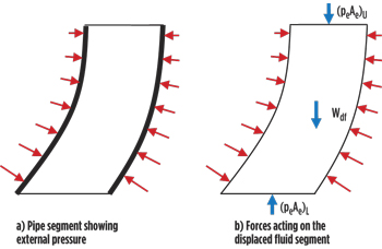
The flaw in the argument is that pressure does not just act horizontally. It acts perpendicular to the pipe wall surface. Hence, there is a vertical force component, acting on the pipe wall, which cannot be neglected. The horizontal components of the hydrostatic pressures, acting on a segment of pipe between horizontal planes, do indeed induce zero-net resultant force and zero moment in the pipe. This can be understood most easily by considering external pressure. Figure 1a shows the external hydrostatic pressure acting on a pipe segment. Figure 1b shows all forces acting on the displaced fluid segment: pressure on the outer surface; weight (Wdf) of the fluid; vertical forces (peAe)L and (peAe)U on the upper lower horizontal planes. Note that throughout this article, external subscripts (L and U, indicating lower and upper levels) apply to all values within the brackets.
 |
| Fig. 1. External pressure acting on pipe segment and displaced fluid |
|
In Fig. 1b, only pressure on the curved surfaces applies horizontal force to the fluid segment. Since that segment is in equilibrium, the net pressure-induced horizontal force is therefore zero. That is true for any thin horizontal slice through the fluid segment. Hence, the net moment due to the horizontal component of pressure, is also zero. The same conclusions, therefore, also apply to the pipe segment. Similar arguments can be used for internal pressure. Hence, only the vertical components of hydrostatic pressures induce forces and moments that contribute to the bending and buckling of pipe segments between horizontal planes.
EFFECTIVE TENSION EQUATION
The Effective Tension equation can be derived various ways (see for example: Lubinski, Young and Sparks 1984 & 2007). Some derivations are based on mathematics; others on physics.
For a pipe under axial tension (Twall), with internal and external cross-sectional areas Ai and Ae, under internal and external pressures (pi and pe), the Effective Tension (Teff) is given by:
.jpg) |
(1) |
In Eq. 1, [Twall - piAi] is the sum of the axial forces in the pipe wall and contents. The third term (peAe) is the axial force in the displaced fluid. By convention, tension is positive. Hence, the signs of the pressure terms (piAi and peAe) are inverted, since those forces are compressive. The equation applies to pipes of any cross-section, not necessarily circular nor even constant section, at any orientation between the vertical and the horizontal. As such, Effective Tension is the amount by which the axial force in the pipe wall, plus pipe contents, exceeds the axial force in the displaced fluid.
For a riser, there is a risk of buckling if Effective Tension is negative (i.e., compressive). As can be seen from Eq.1, this can be caused by high internal pressure, even for pipes with positive wall tension (Twall). On the other hand, external pressure always increases Effective Tension and has a stabilizing effect. Effective Tension, as defined here, is an axial force. However, for a segment of pipe between horizontal planes, the forces perpendicular to those planes are vertical, not (necessarily) axial. Hence the Effective Force (note the name change to avoid confusion) acting on a section making an oblique angle with the pipe axis also needs to be understood.
EFFECTIVE FORCE
The Effective Force on an oblique section is perpendicular to that section. It can be understood in exactly the same way as the Effective Tension. The Effective Force (Feff) is given by Eq. 2, where (Fwall) is the wall tension perpendicular to the oblique section. Areas (Ai and Ae) are now the internal and external areas of the oblique section.
.jpg) |
(2) |
As such, Effective Force on an oblique section is a simple extension of the Effective Tension concept.
APPARENT WEIGHT
For a section of pipe with weights: pipe wall (Wpw), contained fluid (Wcf) and displaced fluid (Wdf), the apparent weight (Wapp) is given by:
.jpg) |
(3) |
The equation applies to pipe sections of any length, any shape (not necessarily constant section), at any orientation between the vertical and the horizontal. Therefore, Apparent Weight is the amount by which the weight of the pipe wall, plus contents, exceeds the weight of the displaced fluid.
CASE STUDIES
Three cases of increasing complexity will be examined, first by considering Effective Forces and second by considering the pressure-induced Applied Forces that act vertically on the pipe walls:
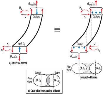
For each case, the pipe is assumed to be cylindrical, for which the horizontal (oblique) sections are elliptical. Lower and upper, internal elliptical sectional areas (Ai)L and (Ai)U are different, and likewise for external sectional areas (Ae)L and (Ae)U. Figs. 2 and 3 show all vertical forces (Effective and Applied) acting on the pipe, as well as the moments (ML, MU) at the lower and upper surfaces, and the shear forces (S). The fluid has no resistance to moments. Hence, the difference in the pipe wall moments (MU - ML) at the segment extremities is the resultant of the couple provided by the shear forces (S), plus the action of all vertical forces, including those induced by the pressures applied to the pipe. The intention is to show that the pressure-induced Applied Forces, acting on the walls of the pipe segment, are always precisely equivalent to those given by the Effective Forces and Apparent Weight.
Case 1: Weightless pipe and contents, under (constant) internal pressure, provide the simplest example. Fig. 2a shows Effective Forces [Fwall – piAi]L and [Fwall – piAi]U acting on the lower and upper oblique sections of the pipe segment. For equilibrium, those forces must be equal and opposite; but they are unaligned. Since the elliptical areas are different, the pressure components (piAi)L and (piAi)U of the Effective Forces are different. Those components act at the centroids of the two ellipses, and transmit both net force and moment to the pipe wall. The reasoning is simple, but will not satisfy skeptics, since it does not explain how the force and moment are transmitted by the fluid to the pipe wall. That can be understood from Fig. 2b.
 |
| Fig. 2. Weightless pipe and contents, with internal pressure |
|
In Fig. 2b, pressure-induced vertical forces (piAi)L and (piAi)U act respectively upwards and downwards on the pipe wall, on the projected areas of the elliptical sections. The lines of action of those forces are vertical through the centroids of the ellipses. For the hatched area in the plan view, the fluid is bounded above and below by the pipe wall; hence upward and downward pressure-induced forces acting on the pipe wall are then equal, opposite and cancel (weightless fluid). Therefore, the pressure-induced net force and moment transmitted to the pipe wall are the resultant of forces (piAi)L and (piAi)U acting on the pipe walls, along axes vertically aligned with the centroids of the ellipses. This agrees perfectly with pressure components of the Effective Forces given in Fig. 2a.
The case of a segment with small deflection, and overlapping the upper and lower ellipses, and overlapping in Plan View, needs to be discussed. The ‘overlap’ has no influence on the Effective Forces, but it does alter the way pressure-induced Applied Forces act on the pipe wall. The plan view in Fig. 2c, which shows the segment projected area, is divided into four parts, with different pressures effects on the pipe wall:
-
For the hatched area, now reduced to two small quasi triangles, the net vertical force is again zero
-
For the partial area of the lower ellipse (white), the pressure impinges upwards on the pipe wall
-
For the partial area of the upper ellipse (white), the pressure impinges downwards on the pipe wall
-
For the overlap between the ellipses (grey), pressure-induced forces are equal, opposite and cancel.
Only Forces 2 and 3 transmit force to the pipe wall. Since they only act on the ‘part ellipses’, determining their resultant may appear daunting. Fortunately, it is not. Since the forces on the (grey) overlapping areas cancel, their effect is neutral. Including them, to complete the forces on the two ellipses, changes neither the net force nor the moment, transmitted to the pipe wall. That net force and moment are once again the resultant of forces (piAi)L and (piAi)U, acting at the centroids of the complete ellipses, in agreement with the pressure components of the Effective Forces, shown on Fig. 2a.
Case 2: Pipe plus contents with significant weight, and (non-constant) internal pressure. This case is slightly more complicated than Case 1. The weight of the pipe wall (Wpw) is included; pressures at upper and lower levels are different, because of the internal fluid weight.
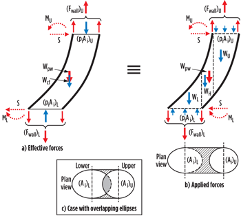
From Fig. 3a, the difference between Effective Forces [Fwall – piAi]L and [Fwall – piAi]U is equal to the weight of the pipe wall plus pipe contents (Wpw+Wcf), which, in the absence of external pressure, is the Apparent Weight. The total pressure-induced vertical force and moment transmitted to the pipe wall is the resultant of the three vertical forces: (piAi)L and (piAi)U acting at the centroids of the lower and upper ellipses, and the weight of the contained fluid (Wcf) acting at its center of gravity.
 |
| Fig. 3. Pipe and contents of significant weight, with internal pressure |
|
Fig. 3b shows the Applied Forces acting on the pipe wall. The upward force, acting above the lower ellipse, is equal to (piAi)L, less the weight of fluid (WL) between the ellipse and the pipe wall above it. Likewise for the upper ellipse, the downward force transmitted to the pipe wall is equal to (piAi)U, plus the weight of fluid (WU). For the hatched area, in the plan view, downward and upward pressure-induced vertical forces acting on the pipe wall differ by the weight of the contained fluid (WH).
Since the sum of the fluid weights (WL+WU+WH) is equal to the weight of the pipe contents (Wcf), the net vertical force and moment transmitted by the fluid to the pipe is the resultant of vertical forces: (piAi)L and (piAi)U acting at the centroids of the lower and upper ellipses, and the weight of the pipe contents (Wcf), acting at their center of gravity. That is in perfect agreement with the Effective Forces shown in Fig. 3a.
Again, segments with small deflections, and overlapping ellipses in the plan view, need to be discussed. The ‘overlap’ does not change the Effective Forces, but it does change the way that pressure-induced Applied Forces act on the pipe wall. The plan view in Fig. 3c shows the segment projected area, divided into four parts, with different pressure effects on the pipe wall:
-
For the hatched area, now reduced to two small quasi triangles, the net vertical (downward) force on the pipe wall, is equal to the weight of contained fluid (WH).
-
For the partial area of the lower ellipse (white), the force that impinges upwards on the pipe wall is equal to the force on the partial ellipse, less the weight of fluid (WL) between that partial ellipse and the pipe wall above it.
-
For the partial area of the upper ellipse (white), the force that impinges downwards on the pipe wall, is equal to the force on the part ellipse plus the weight of fluid (WU) between that part ellipse and the pipe wall below it.
-
The overlapping area (grey) is common to both ellipses. The upthrust on the lower area and the downthrust on the upper area differ by the weight (Wgrey) of the fluid column between them.
Only the first three of the above forces act on the pipe wall. Finding the resultant of those forces appears, at first sight, to be a very difficult task. Fortunately, it is not so. The forces on the overlapping areas (grey), plus the weight (Wgrey) of fluid between them, do not act on the pipe wall. But since they add up to zero, including them has no influence on the net force or moment transmitted to the pipe wall. The forces on the overlapping areas (grey) complete the forces on the ellipses. (Wgrey) completes the weight of the fluid contents (WL+WU+WH+Wgrey= Wcf). Hence, the net force and moment transmitted to the pipe wall are then again the resultant of forces (piAi)L and (piAi)U, acting at the centroids of the complete ellipses, plus the total weight of the pipe contents (Wcf) acting at its center of gravity. This agrees with the pressure components of the Effective Forces, shown on Fig. 3a.
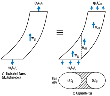
Case 3: Effect of external pressure. Figure 1 already shows the external pressure acting on a pipe segment, and on the displaced fluid segment. The fluid segment (see Fig. 1b) is maintained in equilibrium by the external pressures acting on the curved surfaces, plus vertical end forces (peAe)L and (peAe)U and weight (Wdf). It follows that the global effect of those three vertical forces is exactly equal, and opposite, to the global effects of the pressures on the curved surfaces. Hence, using Archimedes’ argument, the net force and moment transmitted by the external pressure to the pipe wall are precisely the same as those resulting from the three inverted forces shown on Fig. 4a.
 |
| Fig. 4. Effect of external pressure |
|
The same result can be obtained by considering the vertical components of pressure that act on the pipe walls. In Fig.4b, the downward force on the pipe surface above the lower ellipse, is (numerically) equal to the downward force (peAe)L at the lower ellipse, reduced by the weight (WdL) of displaced fluid immediately above that ellipse. Likewise, the upward force on the pipe surface below the upper ellipse is (numerically) equal to the upward force (peAe)U at the upper ellipse, increased by the weight (WdU) of displaced fluid (i.e. acting upwards), immediately below that ellipse.
For the section of pipe corresponding to the hatched area in the plan view, the upthrust resulting from the pressures acting on the pipe surfaces is equal to the weight (WdH) of fluid displaced. But the sum of forces (WdL + WdH + WdU) is equal to the total weight (Wdf) of fluid displaced by the segment. Hence, the equivalent forces on Fig. 4b, obtained by considering Applied Forces, agree perfectly with those obtained on Fig. 4a by applying Archimedes!
Hence, the net force and moment induced in the pipe wall by internal and external pressures can be found from the Effective Forces by superimposing the forces of Fig.4a on those of Fig.3a, or from the Applied Forces by superimposing the forces of Fig. 4b on those of Fig. 3b. Both approaches give the same result.
The pipe segment behaves as if it were subject to a downward force, [(Fwall)L - (piAi)L + (peAe)L], acting at the centroid of the lower elliptical section; an upward force [(Fwall)U - (piAi)U + (peAe)U] at the centroid of the upper elliptical section; and, as if it had weight, [Wpw + Wcf – Wdf]. Those forces are precisely the lower and upper Effective Forces (Feff) and Apparent Weight (Wapp) given by Equations (2) and (3). Net effects of pressures obtained by considering Applied Forces are in perfect agreement with those given by the Effective Tension Concept.
CONCLUSIONS
Effects of pressure acting on pipe segments between horizontal planes have been examined in detail. For such segments, only the vertical components of pressure transmit net force and moment to the pipe wall. Hence, they contribute to bending and buckling.
Since horizontal planes (generally) make oblique angles with the pipe axis, the Effective Forces acting on Oblique Sections have been examined and explained. Such forces have been shown to be a simple extension of the Effective Tension Concept. The influence of the vertical components of pressure on bending and buckling has then been examined in detail for three cases of increasing complexity. For each case, it has been shown that the net force and moment transmitted to the pipe by the pressure, deduced by considering the vertical Applied Forces acting on the pipe wall, agree precisely with those given by the Effective Tension Concept.
The arguments developed have been shown to be valid for pipe segments with large or small deflections, at any orientation with the vertical. Arguments presented are intended to show that Effective Tension is not fiction; that it is easy to understand, and simple to use; that it models perfectly, and correctly, the net forces and moments induced by hydrostatic pressures acting, in and on, pipes and risers. 
ACKNOWLEDGMENTS
The author thanks Andrew Palmer, Joe R. Fowler, Randy Long, Ivar Fylling, Carl Martin Larsen, Michael Montgomery, Stan Christman and Jack Bayless for their participation in the stimulating discussions that led to this article.
REFERENCES
1. Palmer, A.C. and J. A. Baldry, “Lateral buckling of axially constrained pipelines,” Journal of Petroleum Technology, November 1974.
2. Palmer, A.C. and A. Sabtian, “Effective tension in pipeline and riser buckling, Offshore Engineer, October 2012.
3. Lubinski, A., “Necessary tension in marine risers,” Revue de l’Institut Français du Pétrole, Vol. XXXII, No. 2, pp 233-256 and Vol. XXXII, No. 6, pp 873-895, 1977.
4. Young, R.D. and J. R. Fowler, “Mathematics of the marine riser,” The Energy Technology Conference and Exhibition, Houston, November 1978.
5. Sparks, C.P., “The influence of tension pressure and weight on pipe and riser deformations and stresses,” Transactions of the ASME, Journal of Energy Resources Technology, 106, pp 46-54, 1984.
6. Sparks, C.P., Fundamentals of Marine Riser Mechanics, PennWell, 2007.
|
The authors
CHARLES SPARKS worked for 30 years at the Institut Français du Pétrole, where he ran research projects, many of which were related to risers. Since retiring in 2003, he has worked as a consultant on a number of riser projects. He has authored many articles on risers, and recently written a book on the fundamentals of their mechanical behavior. He has a master’s degree in Mechanical Sciences from the University of Cambridge. |
|

.jpg)

.jpg)


