ANANYA ROY and NICOLAS CHAZALNOEL, CGGVeritas
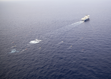 |
| Photo courtesy of CGG Veritas/Dominique Lecuivre Production |
|
Reverse Time Migration (RTM) has been used extensively in the comparatively complex geological domain of the deepwater Gulf of Mexico. RTM technologies employed in the Santos basin offshore Brazil have demonstrated significantly more accurate salt geometry definition and velocity than ray-based migrations. The superior images of salt structures clear the way for a more accurate interpretation of the salt geometry. Furthermore, in areas where poor illumination inhibits conclusive interpretation, RTM with selective Vector Offset Output (VOO) stacking can improve signal-to-noise ratio and aid interpretation.
The information provided by 3D RTM angle gathers for intra-salt tomography ensures a more reliable salt velocity update and an improved image of complex salt. The combined result of applying all these new technologies in the relatively simple salt environment of the Santos basin is a better salt model, a better image of the pre-salt target and, consequently, reduced uncertainty in the delineation of potential reservoirs. These benefits help operators reduce risks in well planning and development.
EVOLUTION OF PRE-SALT IMAGING
Most of the largest oil discoveries in the last decade have been found in the deepwater pre-salt frontiers of the Gulf of Mexico, Brazil and West Africa. These are difficult environments for hydrocarbon production with significant risks. Seismic has always been one of the key de-risking tools for the E&P industry, and as the technology continues to evolve rapidly, it is playing an increasingly important role in helping to delineate new prospects and guide drilling and development plans.
Beginning with the ubiquitous Kirchhoff, ray-based migration algorithms were the state-of-the-art in the industry for decades and proved to be efficient and adequate for most scenarios. However, as the industry exhausted the post-salt opportunities and turned its attention to the pre-salt, the limitations of ray-based migration algorithms became increasingly clear. Attempting to calculate raypaths through the large velocity contrasts between the salt and sediments as well as the complex salt body shapes became impossible, usually resulting in poor-quality images.
At this stage, two directions were available: The development of the beam migration approach and the advancement of what are generally known as wave-equation algorithms. Beam migrations capitalized on all of the strong points of Kirchhoff ray migration with the addition of multi-pathing, thus allowing several different raypaths through the salt to contribute to image points. Controlled Beam Migration (CBM) is one of these beam techniques, and has been fine-tuned to the demands of imaging complex structures. As a result, CBM offers good signal-to-noise ratio and imaging of steep dips such as salt flanks.
Wave-equation methods are based on propagating the seismic wavefield through the velocity model, thereby avoiding the limitations of the ray-based beam methods in the most complex areas. One-way wave-equation algorithms, which propagate the wavefield from the source and receiver only in the downward direction, provided some uplift, but were fundamentally limited.
Two-way wave equation with RTM removes this limitation, allowing the wavefield to propagate both downwards and upwards through the model and, in doing so, accommodates a wide assortment of complex arrivals to image deep pre-salt structures with a new level of accuracy. In reality, one-way wave equation was a stopgap while computing power caught up with the very demanding requirements of RTM.
While RTM is now well established as the recognized standard, imaging technology continues to evolve at a rapid pace, driven partially by new acquisition technology, such as wide-azimuth acquisition. Wide-azimuth represents another response to the challenges of pre-salt exploration in that it was designed specifically to provide better illumination beneath complex salt canopies. Afterwards, seismic processing and imaging had to catch up to make better use of these wide-azimuth datasets. This technology gap resulted in new developments in velocity model descriptions in the form of Tilted Transverse Isotropy (TTI) and new true-3D approaches to processing and imaging, such as RTM 3D angle gathers, to capture the full benefits of azimuthal information inherent in the data. It also inspired an initiative to divide the RTM output into directional vector offset tiles, which will be discussed in greater detail later.
APPLICATION IN SANTOS BASIN
CGGVeritas began serious consideration of the potential benefits of two-way wave equation in the Santos basin after evaluating the applications of advanced RTM tools in the more complex environment of the Gulf of Mexico. The predominate question was whether the additional time and expense of applying RTM in less complex imaging settings like the Santos basin, where the salt geology is relatively simple, would be justifiable.
The quality of the pre-salt image is limited by the accuracy of the velocity model which, in turn, is very sensitive to salt-body definition. Consequently, RTM often is employed not only for final migration, but also for salt interpretation in regions where the salt geometry is complex and difficult to image.1-2 In the Santos basin, RTM typically is used for final migration, but rarely for salt interpretation. Rather, owing to the much less complex salt geometry of the Santos basin compared to that of the Gulf of Mexico, operators in the former prefer to use CBM for interpretation.3 However, it has been shown that, even in the simpler Santos basin, there are areas where a CBM image does not allow conclusive determination of the salt structure. Hence, in those areas, RTM technology can greatly enhance the image, resulting in more reliable salt interpretation, which is crucial to the quality of the final pre-salt image. Moreover, the higher reliability ultimately helps reduce the risk of delineating and developing Santos basin pre-salt fields.
SANTOS BASIN SALT STRUCTURE
The salt body in the Santos basin is a combination of pure halite and sections of layered evaporites. Since the salt body exhibits wide velocity variations, it in essence disputes the accepted assumption that salt has a constant velocity. However as Huang et al.3 explained, this layering gives rise to reflection events that allow for the application of intra-salt tomographic inversion to estimate the internal velocity structure. Typically, this is carried out using the residual move-out curvature from surface-offset CBM gathers. When used near complex salt, RTM subsurface 3D angle gathers can improve the tomographic velocity update and, in turn, the image of the base of salt and pre-salt events.
Even though the dataset used in this discussion represents Narrow Azimuth (NAZ), it is also clear that the true-3D approach developed for processing wide-azimuth data provides an additional uplift. The location of the survey is indicated by the highlighted region on the map of the CGGVeritas Santos basin multi-client surveys shown in Fig. 1. These data were acquired along the East-West direction with 50-m shot spacing, 12.5-m receiver spacing and a maximum offset of 6,000 m.
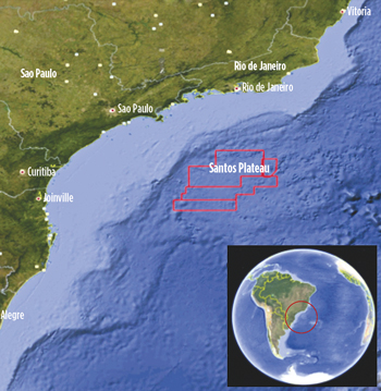 |
| Fig. 1. Santos basin survey locations |
|
CBM-RTM COMPARISON
In the test area, a salt model interpreted purely from CBM images had already been built and showed the presence of steep salt flanks and overhangs. Figure 2a depicts the CBM image of a line migrated using a second sediment flood model with a constant salt velocity inserted in the upper section of the salt overhang structures. At this stage of model building, the shallow parts of all salt overhangs have been defined and a migration with this model should image the underlying salt structures. However, the CBM image in Fig. 2a contains a large number of migration swings that can mislead an interpreter. Figure 2b represents a 35-Hz RTM image migrated using the same velocity model. This image reveals the salt structure with much greater clarity, making it much easier to interpret.
 |
Fig. 2a. CBM image migrated with a second sediment flood velocity model.
Fig. 2b. RTM image migrated using the same velocity model as shown in Fig. 2a. |
|
The two independent salt interpretations derived from the CBM and RTM images were used to build two different salt flood models. Figure 3 compares these two velocity models overlaid on the RTM images migrated using each model. The RTM-based model in Fig. 3b produces a clearer base of salt and pre-salt image, confirming that the RTM-derived salt model is more accurate.
 |
Fig. 3a. RTM image overlaid with salt interpretation from the CBM image in Fig. 2a.
Fig. 3b. RTM image overlaid with salt interpretation from the RTM image in Fig. 2b. |
|
RTM WITH VOO STACKING
Q. Xu et al.4 proposed a technique to divide the RTM output of each shot into a number of tiles (usually nine) with each tile corresponding to a different vector offset range as measured from the shot location, Fig. 4. Given the local geological structure, it is then possible to selectively combine migration outputs from only the vector offsets that contribute to the signal at a given location. For example, if the orientation of the salt flank is known, it is possible to select only the vector offset tiles, which are known to contain the reflection information. This reduces signal contamination by noise from shots not contributing to the illumination of a particular area.
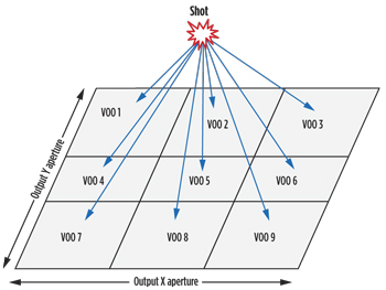 |
| Fig. 4. Division of RTM output of each shot into different tiles, each corresponding to a different vector offset range as measured from the shot location. |
|
Figure 5a shows an RTM image migrated using a salt-flood velocity model. In the highlighted region, the base is unclear and difficult to interpret. Local geology indicates the base of salt at this location must be illuminated mainly by shots to its east. A partial stack that combines only the RTM outputs illuminated from the east (VOO tiles 1, 4 and 7) is shown in Fig. 5b. The contribution by shots from other directions, which is almost all noise, is separated from the signal energy near the base of salt at this location. Accordingly, this Vector Offset Output image of the base of salt is considerably easier to interpret.
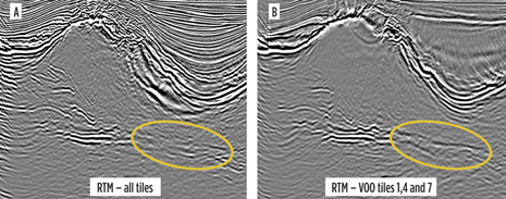 |
| Fig. 5. Full RTM stack (left) and partial RTM stack of VOO tiles 1, 4 and 7 (right) migrated with a salt-flood velocity model. |
|
INTRA-SALT TOMOGRAPHY
For intra-salt tomography, the data provided by CBM gathers is sufficiently accurate when used in salt structures that are simple and where continuous reflections from evaporite layers are available. However, in areas where the halite and evaporites are mixed or the salt structure is complex, RTM produces a better image, and its gathers should provide higher quality residual move-out information for tomography.
To compare intra-salt tomography from CBM and RTM gathers, a test area of about 400 km2 containing regions of both layered and mixed salt was selected. The RTM gathers are 3D subsurface common angle gathers5 that contain both subsurface azimuth and reflection angle information. Since the survey used in these tests is NAZ, the 0° azimuth gathers contained the most information. Huang et al.6 showed that these 0° azimuth gathers are still more reliable for velocity inversion than the commonly used 2D RTM subsurface angle gathers.7
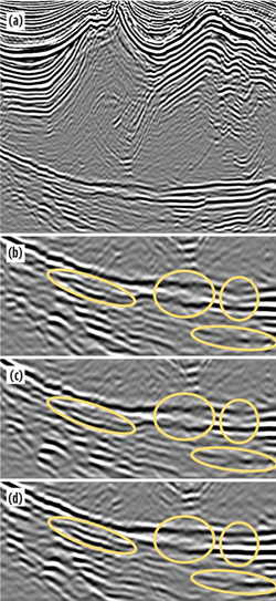
Two migration algorithms were applied using the same constant salt velocity model to output CBM surface-offset gathers and RTM 3D subsurface angle gathers. The CBM stack and gathers at a location with a mixture of halite and evaporites in the salt are shown in Fig. 6a, while Fig. 6b shows the corresponding RTM stack and 0° azimuth gathers. On the CBM gathers, the move-out is broken and inconsistent while it is clean and consistent on the RTM gathers. The CBM gathers have been muted to discard artifacts that resulted from events being focused at multiple depths near a large velocity contrast.8 The RTM is free from such artifacts and its angle gathers do not require muting. The results of tomographic velocity inversion on the two sets of gathers were equivalent where the salt structure is simple and the salt has continuous evaporite layers. In complex areas, tomography on 3D RTM gathers provided a better velocity update. Figure 7 shows a comparison of intra-salt tomography results in an area where the salt is a mixture of halite and layered evaporites as shown in Fig. 7a. Figures 7b, c and d are magnified 25-Hz RTM images of the base of salt at this location. They were migrated with a constant salt velocity, with a salt velocity computed from CBM gathers and, with a salt velocity computed from RTM gathers respectively. On the RTM gather result, in Fig. 7d, the base of salt is more continuous and the pre-salt sediments are more coherent.
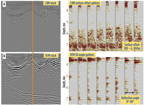 |
Fig. 6a. CBM stack and surface offset gathers.
Fig. 6b. RTM stack and 3D sub-surface angle gathers at the same location as Fig. 6a. |
|
 |
| Fig. 7a. RTM image showing the location of the comparison. Figs. 7b, c and d are magnified RTM images migrated with a constant salt velocity (b), salt velocity from intra-salt tomography on CBM surface offset gathers (c), and salt velocity from intra-salt tomography on RTM 3D angle gathers (d). |
|
CONCLUSIONS
The experience of imaging Santos basin salt using advanced RTM technology clearly demonstrates the advantages that can be achieved even in relatively simple geological environments. The use of RTM, especially in tandem with advanced RTM tools like selective VOO stacking and 3D sub-surface angle gathers, can further de-risk the development of deepwater prospects. 
LITERATURE CITED
1. Reasnor, D. M., 2007, “Salt interpretation practices for depth imaging in the Gulf of Mexico,” The Leading Edge, 26, 1438–1441, doi:10.1190/1.2805762.
2. Buur, J., and T. Kuhnel, 2008, “Salt interpretation enabled by reverse-time migration,” Geophysics, 73, No.5, VE211–VE216, doi:10.1190/1.2968690.
3. Huang, Y., D. Lin, B. Bai, S. Roby and C. Ricardez, 2010, “Challenges in presalt depth imaging of the deepwater Santos Basin, Brazil,” The Leading Edge, 29, 820–825, doi:10.1190/1.3462785.
4. Xu, Q., Y. Li, X. Yu and Y. Huang, 2011, “Reverse-time migration using vector offset output to improve subsalt imaging—A case study at the Walker Ridge GOM.” presented at the 73rd Annual International Conference and Exhibition, EAGE.
5. Xu, S., Y. Zhang and T. Bing, 2011, “3D angle gathers from reverse time migration,” Geophysics, 76, No. 2, S77–S92, doi:10.1190/1.3536527.
6. Huang, Y., B. Bai and T. Huang, 2010, “The application of RTM 3D gathers for wide azimuth data in Garden Banks, Gulf of Mexico,” 80th Annual International Meeting, SEG, Expanded Abstracts, 3298–3302.
7. Sava, P., and S. Fomel, 2003, “Angle-domain common-image gathers by wave field continuation methods,” Geophysics, 68, 1065–1074, doi:10.1190/1.1581078.
8. Xu, S., and T. Huang, 2007, “Migration artifacts and velocity analysis,” 77th Annual International Meeting, SEG, Expanded Abstracts, 3019–3023.
ACKNOWLEDGMENT
This article is adapted from an original paper presented by the authors at the 30th Annual SEG Conference & Exhibition, San Antonio, Texas, 2011: “RTM technology for improved salt imaging in the Santos Basin, Brazil”, SEG Expanded Abstracts 30, pp. 3243-3247.
|
The authors
|
 |
ANANYA ROY received her BE degree in electronics and telecommunications from the University of Mumbai in 2005. In 2009, she graduated with a PhD in electrical engineering from the University of Houston. Since 2010, she has worked as a seismic imager at CGGVeritas, focusing on imaging challenges in the Santos basin and the Gulf of Mexico. |
|
 |
NICOLAS CHAZALNOEL graduated with a bachelor’s degree in geophysics from the University of Strasbourg, France. He is a technical supervisor at CGGVeritas in Houston. He has specialized in seismic processing and imaging for over 14 years, mainly in Houston on data from the Gulf of Mexico, but also on a number of projects in Brazil. |
|


