IAN THOMSON, RAUL KRASUK and MARCOS FREESZ, Baker Hughes Brazil
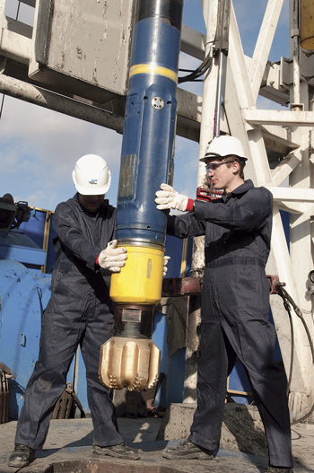 |
| The Baker Hughes Brazil team conducted onshore and offshore tests to gauge the capabilities of a new-generation RSS system, and MWD technologies in drilling through salt for a maximum DLS of 3.95°/30 m with only 81% of the RSS steer force. |
|
A series of groundbreaking Santos basin field trials, using new-generation rotary steerable system (RSS) and measurement-while-drilling (MWD) technologies, has enhanced understanding of the directional drillability of ultra-deepwater mobile salt bodies.
The field trails followed an unprecedented onshore directional drilling test conducted on a creeping salt formation in northeastern Brazil. The test, which utilized an advanced RSS and a specially engineered MWD drilling optimization tool, was orchestrated to further the understanding of salt drillability, particularly with respect to steerability capabilities and directional assembly stability.
Owing to the encouraging results of the one-of-a-kind onshore examination, investigators employed the advanced RSS and MWD systems in three deepwater directional tests through thick and mobile salt sections. The latest generation RSS technology achieved excellent build-up rates (BUR) in both the 14¾-in and 17½-in. intervals in which it was used. The planned directional trajectory was achieved consistently with drilling efficiencies in the directional sections comparable to offsets drilled vertically in the same field. Close real-time monitoring of the downhole drilling parameters and dynamic conditions was recognized as critical to the success of the field trials.
SALT DRILLING CHALLENGES
Over the past 10 years, offshore salt drilling activity has increased appreciably worldwide, especially in Brazil where world-class oil discoveries have been made in carbonate reservoirs underlying thick salt bodies. Drilling through salt can be extremely challenging, even more so in projects where severe salt mobility is common. Salt mobility or creep rate mainly is a function of downhole temperature, geomechanical stresses around the salt body, and salt mineralogy.
In Brazil, many deepwater wells targeting hydrocarbons below the salt are still considered exploratory or appraisal, with the salt bodies typically being drilled vertically. Because of the gradual transition of deepwater projects into the development phase, the emphasis on advancing directional drilling capabilities through salt is increasing at a rapid pace.
The drilling community perceives directional drilling through salt as an extremely daunting proposition, primarily on account of the plastic nature of the evaporates and the wellbore stability problems commonly experienced in the past. The ability to consistently perform directionally in salt and achieve the planned BUR has been an ongoing issue for years. Generally, many aspects dictate the BUR capability in salt, including the evaporate rock being drilled, the salt creep rate, the BHA and bit design, among others. The evolution of directional drilling technologies in recent years, in tandem with the global experience gathered in salt drilling, has enhanced the confidence of both operators and service companies to attempt and drill directionally through salt intervals.
Prior to drilling the first directional salt section in the most prolific field in the ultra-deepwater Santos basin, Baker Hughes laid the foundation for the first steerability test to be conducted in the salt section of a land well. The first-ever test of its kind, conducted on a well in northeastern Brazil, employed the advanced RSS, typically used in deepwater wells, and the specialized MWD tool, both of which were to be used in the subsequent Santos basin field trials.
The RSS system steers a well by applying precisely controlled continuous forces against the borehole wall from three extendable ribs/pads located on the short non-rotating sleeve. The magnitude and direction of the steering vector are programmable from surface, and once programmed into the tool, both parameters are available continuously, where they are monitored constantly and readjusted using the downhole closed-loop steering algorithm. The BUR capability is proportional to the magnitude of the steering vector, which is adjustable from 0-100% steer force. To maximize the BUR capability of the drilling system, a flexible sub with stabilizer usually is positioned on top of the RSS steering unit. Donati et al. and Calderoni et al. earlier presented a more detailed description of the RSS first-generation functionality and concept.1,2
TEST GOALS, PROTOCOL
The primary objective of the onshore test was to evaluate and benchmark the BUR capability of the RSS in a salt formation, with the learnings to be applied in the Santos basin deepwater directional salt sections. The BHA utilized in the test was very similar to those used normally in deepwater operations, hence the test results could be deemed meaningful to real-world applications. The BHA primarily comprised a 9½-in. RSS configured for a 12¼-in. hole; a flex sub with a stabilizer positioned immediately above the RSS to promote the three-point geometry and flexibility to the BHA to permit higher BURs; and a real-time mechanics and dynamics diagnostic MWD tool situated immediately above the flex stab.
Heisig et al.3 discussed in detail the concept, functionality and capability of the drilling mechanics and dynamics diagnostic MWD tools. However, for the scope of this discussion, it is important to mention the ability of the tools to accurately measure downhole torque, downhole weight on bit (WOB), bending moment and vibration levels. The measurement of these downhole parameters is extremely important for understanding the drilling system behavior while performing directional work at different BURs, tool configurations and lithologies.
The test also employed a 12¼-in. PDC bit with six blades and a 16-mm cutter, and was fitted with six 16/32-in. jets. Since the evaporate section was composed primarily of carnallite with halite and tachydrite sequences, oil-based drilling fluid was used throughout the test. The plan was to sidetrack out of a cement plug in salt and initiate the test protocol, which was earlier established jointly by the operator and service company. Amaro et al. described some of the well construction and planning criteria used in the northeastern Brazil onshore test.4
The primary objective of the test was to qualify and quantify the RSS directional performance in salt with respect to:
-
Tool configuration parameters for various intervals of build-up
-
The drillability of the carnallite and halite evaporate formations, and the dynamics response of the systems
-
The effects of vibration on tool performance.
The jointly established test protocol called for initiating the kick-off/sidetrack according to the well plan. This would include registering optimized drilling parameters for the most efficient drilling conditions, and afterwards, turn the well to the desired azimuth. From there, the RSS Steer Force (SF) applied to the RSS ribs would be increased gradually, utilizing the same drilling parameters to record the BUR achieved with the respective SF employed. If the actual BUR achieved was greater than 6º/30 m, the SF would be systematically reduced, beginning with 45% SF to drill approximately 15 m with the drilling parameters adjusted accordingly. Afterwards, the SF would be increased to about 60%, with 27 m drilled using the same drilling parameters. The SF would then be increased to 75%, and another 27 m would be drilled with the same parameters. From there, the SF would be increased sequentially to 90% and 100%, where two 27-m sections would be drilled, also using the same parameters.
TEST EXECUTION
The BHA was assembled, programmed and tested, and tripped in hole to the top of the cement at 1,021 m. The cement, which was drilled inside the 13⅜-in. casing to the shoe, was homogeneous and presented high resistance. At this depth, the well inclination was 2°, and the azimuth was approximately 220°. The RSS was configured to sidetrack/kick-off with 90% of SF and 330° steer direction (SD). The SD has gravitational reference, where either 0° or 360° represents the high side of the well, and 180° represents the low side. In this case, according to the well trajectory, 30° means leaving/deviating/kicking-off from the high left side aligning the well with an azimuth of 85°.
Once it was observed that the inclination values in the RSS near-bit inclination (NBI) were higher than 3°, and the bending moment values from the MWD tool had varied more than 100% from the initial value in about 10 m, the sidetrack could be confirmed. Howes et al. previously described how the real-time downhole bending moment values help with sidetrack operations.5
At this point, it was decided to change the RSS operation mode to maintain the well inclination and start turning the wellbore to the left, as per the planned trajectory. The RSS was set to hold to maintain a target inclination of 3.2°, with 45% of Build Force (BF) and 87% of Walk Force (WF). With that RSS configuration, the NBI remained fairly steady, with little fluctuation on the bending moment and a consistent turn to the left, Fig. 1.
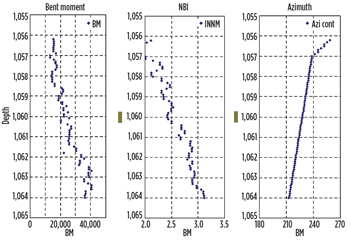 |
| Fig.1. At 10 m, the bending moment varies more than 100% from the initial value, followed by an increase close to 2° in the NBI, with a tendency of turning to the left, confirming the sidetrack. |
|
To optimize drilling performance and keep the stick slip below severity level 5, the following parameters were used: 110 rpm, 500 gpm, and WOB from 20 klb to 25 klb. After the wellbore was steered to the desired azimuth, the BUR test started with a progressive increase in the RSS steer force, and with controlled drilling parameters for consistent, reliable results. Stick slip values were kept below level 5, and the average ROP throughout the test was 10 m/hr.
With its initial SF set to 45%, the RSS achieved a BUR of 3.2º/30 m (3.2º/100 ft), and with 67% SF, the actual BUR was 4.5º/30 m. With the RSS configured with 87% SF and 0° steer direction to keep building angle, the variation in near-bit inclination indicated doglegs higher than 6º/30 m (6º/100 ft) could be achieved, which was outside the scope of the test. Accordingly, it was decided to end this interval after drilling only 5 m and reduce the RSS steer force from 87% to 77%, to maintain the planned BUR. With 77% SF, the RSS achieved a BUR of 5.72°/30 m, and with 71% SF a BUR of 4.8°/30 m. The wellbore angle was built from 2° to 38° inclination and turned to the left from 238° azimuth to 140° azimuth, Fig. 2.
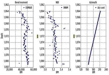 |
| Fig. 2. The bending moment is now more constant, and the NBI varies just a little, maintaining the tendency of turning to the left. |
|
Beginning at around 1,134 m to 1,153 m, the registered MWD tool bending moment readings indicated the presence of a subtle spiraling effect, which disappeared naturally and most likely was related to a sequence of different evaporate types within the main salt body. The dogleg severity (DLS) values were negatively influenced by the increase of the spiraling effects. When the spiraling pattern was broken, the BUR results correlated again with the expected values, Fig. 3.
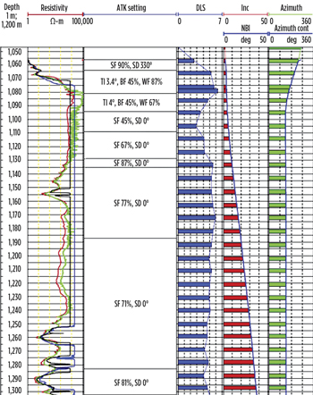 |
| Fig. 3. Inclination and azimuth variation throughout the test along with the DLS according to the different RSS settings. |
|
TEST CONCLUSIONS
Results of the onshore mobile salt drillability tests yielded a host of significant lessons that could be applied in the field trials, including:
-
The RSS tool presented the ability to steer in the salt without any problem, either while turning the wellbore (change in azimuth) or building angle, achieving a higher BUR than expected.
-
The BUR presented a consistent, linear relationship with the steer force applied at the RSS ribs. During the planning phase, it was agreed to utilize the full 100% RSS SF capacity; however, at 87% SF the BUR was on the order of 6.4º/30 m (6.4º/100 ft). A linear relationship also was observed between the RSS SF and the bending moment readings from the MWD tool. This relationship suggested a consistent increase in the bending moment when higher SF is applied at the RSS ribs, Fig. 4.
-
For a short interval of the run, it was possible to quantify the spiraling negative effect on the RSS BUR capability. With borehole spiraling, the interval from 1,134 m to 1,153 m had 5.42°/30 m BUR. In the interval from 1153 m to 1187 m, where the borehole spiraling phenomenon did not present itself, the BUR increased to 5.72°/30 m with the same RSS SF.
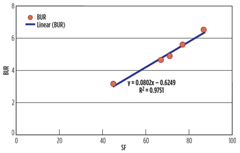 |
| Fig. 4. Correlation between BUR and SF values shows a linear trend (97% R2), proving the success of the test related to the force and to the expected build rate. |
|
DEEPWATER DIRECTIONAL TRIALS
The BUR results of the onshore test increased confidence sufficiently to encourage the drilling of directional wells in mobile salt formations in a prolific Santos basin deepwater field that would include building angle from vertical or low inclinations. Unlike the onshore test, the series of deepwater directional salt sections would be drilled in 17½-in. and 14¾-in. hole intervals.
Directional well #1. The plan was to kick the well off within the salt at about 4° inclination and build up angle to 24° inclination with 2°/30 m dog leg severity and maintain tangent to the section TD at over 5,000 m. The 2D well trajectory was built exactly as per plan (Fig. 5), with no difficulties regarding RSS steerability and BUR capability. Along the build-up section, the maximum build force applied at the RSS ribs was 45%, and the maximum BUR achieved was 2.9°/30 m. In this application, the BUR, in comparison with the RSS steer force, was aligned perfectly and consistent with results achieved in the onshore steerability test (3.2°/30 m with 45% steer force). The bending moment values that were transmitted in real time to surface during the operation, along with the RSS near-bit inclination data, were fundamental for assuring the kick-off and closely monitor the BUR values, Fig. 6.
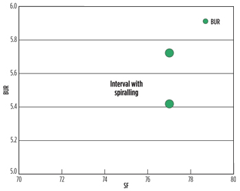 |
| Fig. 5. Decrement on BUR capability (around 0.3°/30 m) due to the spiraling effect considering the same RSS SF of 77%. |
|
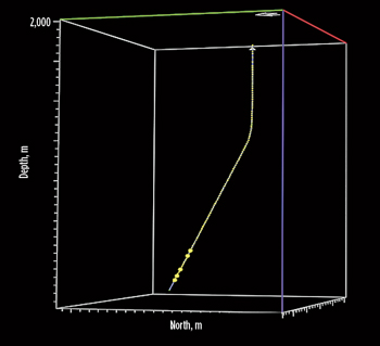 |
| Fig. 6. Trajectory of directional deepwater well #1. |
|
The targeted salt section was composed mainly of halite with short intervals of carnallite and anhydrite. A total of 1,850 m of salt was drilled with a BHA comprising a 9½-in. RSS configured to a 14¾-in. hole, an acoustic LWD tool, and a 9½-in. drilling mechanics and dynamics diagnostic MWD tool, which delivered valuable real-time downhole information on WOB, torque, bending moment and vibration. The BHA also consisted of a 14¾-in. PDC bit with six blades and 16-mm cutters.
Throughout the run, the average on-bottom ROP was 24.7 m/hr, which was comparable to those achieved in the vertical salt sections of offset wells. During the interval, the drilling parameters were adjusted (WOB—20 to 40 klb, and rpm—120 to 170) to mitigate and keep the stick slip levels at a tolerable level and maximize the drilling performance. A minor walk tendency to the left was observed, but easily controlled by adjusting the forces at the RSS ribs to counteract the formation’s natural walk tendency.
Directional Well #2. Following the impressive results achieved on the first directional well, a second directional salt section was drilled, in the same deepwater field. A BHA very similar to the one used on the previous well was used in this trial with the exception of the 14¾-in. PDC bit that included seven blades and 16-mm cutters. The 2D well trajectory again was built exactly as per plan (Fig. 7), and the maximum build force applied to the RSS ribs was 45% to build angle in salt from 2.4° inclination at 3,030 m to 30° inclination at 3,392 m. A 30° inclination tangent was maintained to section TD and the maximum DLS achieved during the run was 2.5°/30 m. A total of 2,227 m of salt was drilled over 175 circulating hours, with an average on-bottom ROP of 25.4 m/hr. The drilling parameters used throughout the run were very similar to what was used on the previous well.
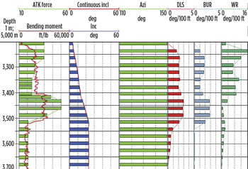 |
| Fig. 7. RSS rib forces and the bending moment values, throughout the directional work performed, along with the wellbore inclination, azimuth, DLS, BUR and walk rate (WR). With 50% Steer force 3°/30 m DLS was achieved. |
|
Directional well #3. A third directional salt section with a higher inclination than the previous two was drilled in the same Santos basin field. The build-up section was drilled in the 17½-in. hole and the tangent section in the 14¾-in interval, Fig. 8. For the build section, the BHA comprised the same 9½-in. RSS configured for 17½-in. hole, a 9½-in. mechanics and dynamics diagnostic MWD tool, and an acoustic LWD tool. A 17½-in. PDC bit with seven blades and 16-mm cutters was also used to drill this section. A similar BHA was used for the 14¾-in. tangent section, including the seven-bladed 14¾-in. PDC bit with 16-mm cutters.
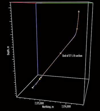 |
| Fig. 8. Trajectory of directional deepwater well #3 |
|
The 17½-in. well trajectory was built exactly as planned from 8.8° inclination at 3,015 m MD to 49.6° inclination at 4,490 m MD, Fig. 9. The planned DLS was 3°/30 m, and the maximum build force applied to the RSS ribs was 81%, which accounted for a maximum DLS of 3.95°/30 m. A total of 1,475 m of salt were drilled with an average ROP of 19 m/hr. Steerability was trouble-free throughout the interval, and the drilling dynamics behaved as expected.
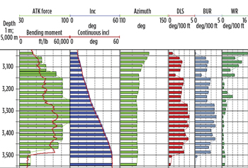 |
| Fig. 9. Bending moment values, throughout the directional work performed, along with the wellbore inclination, azimuth, DLS, BUR and walk rate (WR). With 100% steer force 4°/30m DLS was achieved. |
|
The 14¾-in. section was drilled, keeping the 49.6° inclination tangent without any concern related to the directional trajectory. The maximum force applied to the RSS ribs was kept at 32% to counteract the natural formation walk tendency observed earlier. A total of 1,365 m was drilled in the salt at an average ROP of 28.5 m/hr.
CONCLUSIONS
The successful directional drilling of ultra-deepwater mobile sand sections effectively validated the results seen in the onshore steerability tests. Even in the high-inclination 17½-in. interval, the BHA featuring the new-generation RSS and MWD technologies achieved a maximum DLS of 3.95°/30 m with only 81% of the RSS steer force. The trials also validated the exceptional capacity of the advanced RSS to successfully kickoff from near vertical (2.4° inclination) in salt. The results of the field trial promise to increase the confidence level in the directional drilling of ultra-deepwater salt sections, as operators steadily transition from the exploration to development mode. 
LITERATURE CITED
1.Donati, F., J. Oppelt, A. Trampini and D. Ragnitz, “Innovative rotary closed loop system -- engineering concept proven by extensive field application in the Adriatic Sea,” SPE paper 39328, presented at IADC/SPE Drilling Conference, Dallas, Texas, March 3-6, 1998.
2.Calderoni, J., A. Oppelt, A. Ligrone, and S. Trampini, “Automated steering systems applied to complex horizontal well in South Italy,” SPE paper 50379, presented at SPE International Conference on Horizontal Well Technology, Calgary, Alberta, Canada, Nov. 1-4, 1998.
3.Heisig, G., J. Sancho. and J. D Macpherson, “Downhole diagnosis of drilling dynamics data provides new level drilling process control to driller,” SPE paper 49206, presented at the SPE Annual Technical Conference and Exhibition, New Orleans, Louisiana, Sep. 23-27, 1998.
4.Amrao, R., C. J. de Castro G., H. de Lucena L., J. L. Falcão, R. Fátima, T. Lomba, E. Alcofra and L. Modesto, “Build-up construction in salt formations,” OTC paper 21506, presented at the Offshore Technology Conference, Houston, Texas, May 2-5, 2011.
5.Howes, T., M. Farouk, M. Darwish, W. Koroletz, A. Ismail, Moustafa and Heisig, “Real-time well tool face information reduces directional uncertainty and risk in difficult sidetracks in Gulf of Suez,” SPE paper 128526, presented at North Africa Technical Conference and Exhibition, Cairo, Egypt, Feb. 14-17, 2010.
ACKNOWLEDGMENT
This article is adapted from OTC paper 22604, “Unique salt drilling steerability test: Advanced RSS proved outstanding build-up rate capability in Brazil mobile salt formations,” presented by the authors at the Offshore Technology Conference Brasil, Rio de Janeiro, Oct. 4-6, 2011.
The authors
|
| IAN THOMPSON is the Drilling and Evaluation sales manager for Baker Hughes Brazil. During his nine-year career, Thomson has held a variety of engineering positions at Baker Hughes, including drilling application engineer for the Gulf of Mexico Deepwater Operations. Before his present appointment, he served as a senior drilling engineer and pre-salt manager. Mr. Thomson holds a mechanical engineering degree from the Federal University of Rio de Janeiro and a petroleum engineering post-graduation degree from the Rio de Janeiro Catholic University. |
|
| RAUL KRASUK is the former drilling technical manager for Baker Hughes Brazil, where his primary focus was on high-performance deepwater drilling, particularly in the pre-salt. During his 25-year career, he has held a number of operational and engineering positions within South America. Mr. Krasuk holds a degree in mechanical engineering from the National Technological University, Santa Fe, Argentina, and a post-graduate degree in petroleum engineering from the National Petroleum Institute of Argentina. |
|
| MARCOS FREESZ is the Drill Bits Product Line operations manager for Baker Hughes Brazil, which he joined in 2003 after working with a Brazilian onshore independent operator. He has held a variety of positions, including junior engineer, Drill Bits Product Line district engineer and pre-salt project manager. Mr. Freesz holds a degree in petroleum engineering from the Universidade Estadual do Norte Fluminense, Rio de Janeiro, Brazil. |
|


