TOM SANDERS, CLIFF HOGG, PAT YORK and FRANZ TOMPEK, Weatherford International; and ALI FERHAT, Sonatrach
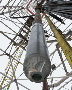 |
| Solid expandable liner systems significantly reduce sizing limitations and provide greater size and flexibility, enabling the creation of larger laterals and optimally sized completions. |
|
Conventional casing exits typically result in significant size step-downs for the resulting production liners. This, in turn, limits the completion options available, particularly for water shut-off. The development of solid expandable liner systems has significantly reduced such sizing limitations and provides greater size and flexibility, enabling the creation of larger laterals and optimum-sized completions. The ability to run expandable liners through a conventional casing exit window has been of some concern due to much higher DLS and possible damage to expandable pipe due to rugged window (if not properly milled and polished).
Six recent well recompletions in Hassi Messaoud field, Algeria, utilized shallow-angle casing exit technology in conjunction with solid expandable liner systems to optimize a workover campaign and revitalize an aging field. Sonatrach, the field operator, faced recompletion challenges such as existing well size constraints, reducing top-down drilling cost, and maximizing completion clearance while creating maximum reservoir contact (MRC) wells. The combination of shallow angle and expandable technology proved to be beneficial by reducing the dogleg severity (DLS) at the window exit, reducing the risk of expandable pipe damage across the window exit, and allowing the solid expandable liners to be run out the window and seal above the window. Once in place, these liners were cemented and expanded successfully in both the openhole and through the casing exit window. Such integration of optimized casing exit and expandable liner technologies is a proved to be a successful strategy for re-entry workover wells. This strategy has successfully increased production in this field and others, facilitating the economical development of remaining oil reserves.
BACKGROUND
The Hassi Messaoud field, located in Algeria’s Ouargla province, was discovered in 1956. With reserves of approximately 6.4 billion bbl, the current production is approximately 350,000 bopd from a Cambrian sandstone reservoir situated in a large dome. Production depths are approximately 11,000 ft with the oil column approximately 900 ft in height.
The field operator embarked on the workover campaign to increase production rates from previously drilled wells, some of which have a 40-year legacy. However, the newly planned workover campaign presented many technological constraints and challenges. In the past, gradual depletion of the reservoir had led to an increased differential pressure between subsequent exposed intermediate formations, which caused wellbore instability and production issues that forced the operator to shut-in the wells. The operational objective for the new workover campaign was to implement the most cost-effective solution to return the wells to production, while optimizing the best overall cost/risk benefit.
Solid expandable technology was selected to overcome the associated restrictions of slim-bore configurations in the wells, which required isolation of the two intervals. The solid expandable system provided the operator a solution to complete the well with a 5-in. openhole (OH) diameter interval across the Cambrian reservoir by maximizing the internal diameter (ID) of the casing string used to isolate the over-pressured intermediate shale interval. The solution consisted of extending the 7-in. casing shoe to the top of the reservoir using 5½ in. expandable tubular, which was tied back into the host 7-in., 32.0 lb/ft casing. This 5½-in. solid expandable system provided a post expansion ID of 5.395 in. and a special drift of 5.3 in., reducing the host casing ID by only 12.9%, Fig. 1.
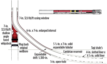 |
| Fig. 1. The desired drill path to the reservoir required a sidetrack from the horizontal portion of the existing well. |
|
PLANNING WITH BEST PRACTICES
When the project concept was first planned, emphasis was placed on utilizing best practices developed in similar projects that minimized the learning curve with a new customer in a new operation. Meetings conducted with all department heads helped identify and classify any risk that was known or anticipated for the operations. Based on this data, a failure mode effects analysis (FMEA) was developed to quantify and qualify the type and severity of risk using the following eight disciplines of problem solving:
Determine the objective to identify the potential problem and relevant corrective actions and contingencies.
-
Investigate root cause(s) of historic incidents.
-
Determine if corrective actions and contingency measures will effectively reduce risk to as low as reasonably possible (ALARP).
-
Select and list proposed corrective actions as identified by risk priority number (RPN) value.
-
Implement and validate the plan and contingencies in the well program.
-
Perform post job reviews with lessons learned captured to review and establish permanent corrective action(s).
-
Establish permanent corrective actions as best practices.
-
Monitor each job to ensure best practices are implemented.
Proper attention to preparing the well is critical to job success when utilizing solid expandable casing. Mechanical manipulation for working the liner to final setting depth is limited with solid expandable casings due to the inability to rotate the liner and the limitation on compression and tensile forces that can be applied to the solid expandable casing. These limitations restrict the ability to manipulate the pipe if the liner becomes stuck. Additionally, situations that make the installation more difficult than with conventional liners include stabilizing losses, under-reaming ledges, working though severe DLS intervals, etc. The success of the expandable casing installation is highly contingent on taking the time and using proper methods, equipment, and wellbore cleanout tools to prepare the well.
Optimizing the installation requires working closely with the solid expandable casing service provider, not just during the solid expandable installation process, but also during wellbore planning, preparation and drilling phases. During the prior drilling and cleanout phases, both the operator and the expandable service provider have an opportunity to properly prepare for the job, evaluate existing conditions, and develop risk/mitigation measures to ensure that the best options are used and contingency measures are in place in advance of mobilizing and installing the solid expandable casing (Waddell 2004, Sparling 2004, Grant 2005, Hogg 2012, Al-Umran 2008, Jeffre 2005, Rivenbark 2006).
Certain parameters most affecting a successful installation of solid expandable tubulars through a casing window were identified as follows:
-
Age of the well/base casing, and casing integrity to install the whipstock
-
Correct correlation to set the whipstock at the correct depth
-
Correct orientation to position the whipstock
-
Multiple casing strings to section mill, which introduces additional risk
-
Metal debris removal after setting the whipstock
-
DLS immediately after the whipstock and subsequent drilled interval.
An important factor affecting the successful implementation of solid expandable tubulars through a milled casing window is the physical characteristic of the window itself. A properly created, conditioned window greatly decreases the possibility of damage to the expandable tubulars and increases the likelihood of a successful expansion. Without such quality control (Fig. 2), the potential damaged areas can become sources of wall thinning and stress concentrations, and are susceptible to failure while enduring the high-hoop stress during the expansion process.
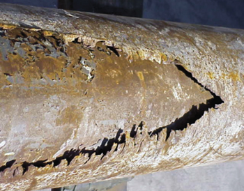 |
| Fig. 2. Improper mill selection or milling procedures, or window placements in poor/no cement quality casing depths can lead to inadequate window geometries, creating a potential for severe damage to the solid expandable tubulars (Grant 2005). |
|
Several case histories suggest that connection failure during expansion cause most of the catastrophic failures downhole. The three main mechanisms of connection failure during expansion include:
-
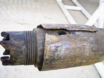
Structural failure in the connectors, often in the box section caused by scratches and scars inflicted during running pipe in the hole and exceeding defect tolerance for the given material and amount of expansion, Fig. 3 (Umran 2008, Zhou 2004, Jeffre 2005, Rivenbark 2006 and Ring 2007)
-
Tensile failure caused by a combination of low efficiency in the connectors and high axial stresses caused by pipe being put in “fixed-fixed” conditions and not able to shrink, in addition to tensile stresses resulting from application of expansion pressure
-
Connection failure due to erosion and washouts caused by a leak in the connection seal that continues to worsen due to sustained exposure to the internal pressure differential and tensile or compressive axial loading during expansion.
|
|
| Fig. 3. Damaged expandable casing connection (Umran 2008). |
|
An enhanced window increases favorable conditions for a successful solid expandable casing installation. The optimum sidetrack system involves using a defined window geometry milling system that features a single-trip milling machine with a hydraulic/mechanical-set anchor packer and an orientation latch coupling. This design allows the system to be used in an existing casing string at a predetermined depth and azimuthal orientation prior to hydraulically anchoring the packer and latch. The process of precision milling the window in the existing casing, in the correct radial and axial position, is critical to subsequent operations. This design also addresses a major concern within the industry—a reliable, repeatable orientation. It allows for precise window alignment with respect to the orientation device or anchor packer to be milled so that a liner can be placed and cemented for re-entry and isolation purposes.
SCOPE OF WORK
To achieve a uniform ID across the reservoir required sidetracking from the existing 7-in., 32.0 lb/ft casing using a shallow-faced whipstock to reduce stress forces on the drilling assembly and expandable tubular system. Minimizing additional forces induced through deviated trajectories significantly reduced the chances of failure across the expandable connectors. Premium threads enabled the system to be run and set in highly deviated sections that had a DLS up to 14°/30 m (Saad 2010, Hamoudi 2011, Ferhat 2010).
Scope of operations. The operational process consisted of the following procedures:
-
Set a shallow faced whipstock within the 7-in. 32.0 lb/ft casing.
-
Drill a SR 6 in. OH across the TAGS section to the top of the Cambrian reservoir.
-
Enlarge the 6-in. OH to 7 in. using an underreamer.
-
Run and set a 5½ x 7-in. solid expandable liner.
-
Drill with a 5-in. directional BHA across Cambrian reservoir.
-
Complete the well with 7-in. 32.0 lb/ft production packer set on e-line and 4½-in. tubing with anchor completion.
Casing exit considerations and results. Most conventional whipstocks utilize concave angles of 3° or less. The benefits with slopes of this angle include shorter windows that result in less milling time and reduced cuttings to be removed to surface. Shorter windows also allow for quicker deflection from the main bore, which is often important when designing drill path trajectories. In exchange for these potential benefits, greater bend of drillpipe is necessary as it is forced out of the mainbore casing by the concave face of the whipstock. The resulting sidewall bending forces make it more difficult to convey the solid expandable casing. The trajectory of the wells put the solid expandable casing in large DLS situations. This predicament puts tremendous loads on the expandable casing and its connectors. In the past, several major expandable system failures were attributed to relatively poor thread connection integrity in conjunction with harsh application environment, i.e., “fix-fix with a large DLS or wellbore tortuosity.” However, some service providers have realized the challenges and addressed these system inefficiencies through superior system design (expansion running tools and expandable casing and connector) and in-depth system qualification testing (Hogg 2012, Al-Umran 2008, Umran 2008, Zhou 2004, Jeffre 2005, Rivenbark 2006 and Ring 2007).
Longer window length. For the Hassi Messaoud campaign, the operator decided to increase the overall window length to reduce the DLS through the junction area, therefore lessening the potential sidewall bending forces on the solid expandable casing. The selected solution utilized a casing exit system with a longer, shallower whipstock face that provided a much longer casing exit window, but still could be milled in a single trip. Most whipstock systems share similar design specifics in utilizing concave angles about three degrees or less. This 3° angle typically provides a window that is long enough to pass tool strings out the exit window, while still allowing for the milling operations to be conducted in as few trips as possible. Although these systems originally took three or more trips to land the whipstock and mill the window, improvements in milling technology and anchoring techniques now make such window creations possible in only a single trip. Currently, a typical single-trip casing exit in 7-in. casing will result in a window length of approximately 8 ft. With such a window length, 15°/100 ft for the DLS is to be expected. In order to reduce this DLS and its impact on the solid expandable casing, the operator selected a whipstock with a shallower concave angle of only 2°. This more gradual angle in turn created a longer window and reduced the DLS. With a reduced angle concave, the window is typically 12 ft in length, representing an approximate 50% increase as compared to the more typical 3° whipstock systems. The resulting DLS realized from such a longer window length has been calculated at around 7.5°/100 ft, which provides a significant improvement over the shorter whipstock assemblies.
Optimum window geometry. Although the longer concave length provides the capability to mill the extended window in a single trip, the milling system itself was selected with the objective of creating optimum window geometry in a single milling run. This system consisted of a milling BHA utilizing three separate mills, Fig. 4. The lowermost lead mill utilizes a combination of crushed carbide and carbide inserts and is designed to provide the initial casing exit cut while also providing the primary formation drilling capability once through the casing. Directly above the leading mill is a combination full gauge watermelon “secondary” mill and flexible joint. This key component is designed to mill out the upper portion of the casing exit window while the flexible nature of the joint provides enough bend to both ensure a proper trajectory of mills along the concave scoop and ensure maximum transmission of string weight to the lead mill as it begins drilling formation rat hole.
|

|
| Fig. 4. The key to milling the shallower angle window in a single trip is the use of multiple mill components in the milling BHA. |
|
The uppermost milling component in the BHA is a full-gauge watermelon “steering” mill. This mill provides a final polishing/reaming capability through the window, ensuring proper window geometry for the completed casing exit. The full gauge nature of the mill helps keep the lowermost mills properly situated against the concave during initial milling operations, reducing the potential premature kick off of the mills from the concave. As a result of this three-component milling system in conjunction with the longer concave design, it became feasible to create a casing exit in a single trip. This design and process resulted in minimum sidewall loading forces while running and expanding the solid expandable casing and on the drillstring during openhole drilling operations.
Single-trip casing exit installation. Along with the concave and mill design, the anchoring component for the whipstock assembly was also selected based a single-trip casing exit installation. To meet this need, an anchoring system attached to the milling assembly with a mechanical shear bolt was utilized. This hydraulic setting assembly allows running the anchor, whipstock, and milling system all in a single run. Once on depth, the desired whipstock orientation can be obtained using conventional survey tools or a gyroscopic survey. The anchor can then be actuated using either hydraulic pressure or mechanical force. Once the anchor has been set, the milling assembly is then sheared from the whipstock assembly with applied load and the casing exit milled without the need for additional trips in and out of the hole.
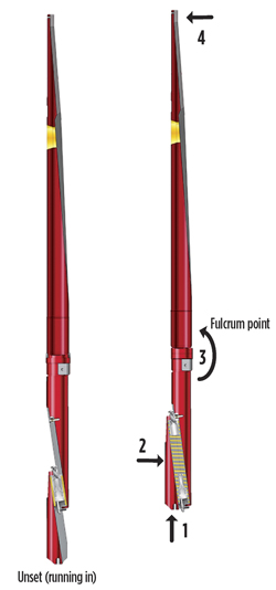
Low-side casing exit. Finding a casing exit system capable of providing a low-side casing exit was the final key requirement for this particular project. As previously noted, a low-side exit generates concerns about the concave assembly falling into the path of the drillstring as a result of gravity. To prevent this from occurring, a simple method was needed to ensure the whipstock assembly could be held securely against the high side of the casing ID. The solution to such a requirement is a “fulcrum” point below the bottom of the whipstock face that forces the concave assembly to pivot away from the actual casing exit area, preventing any potential interference with BHAs departing the casing. For this event to occur, the casing exit system needed to be run in conjunction with an anchor system utilizing a unique eccentric slip system. This anchor system utilizes a setting mechanism that, when actuated by hydraulics or mechanical means, drives a wedge upwards, thereby engaging the slip assembly tightly against the casing wall. By using a wedge-type slip configuration, the anchor offers a much larger range of casing size compatibilities as compared to the more conventional “slip and cone” anchoring systems. As the wedge is driven upwards, the sideways motion, in conjunction with the fulcrum point, creates a force in the opposite direction, away from the intended casing exit. It is this force that holds the concave against the high side of the casing and prevents potential interference with the BHAs, Fig. 5.
|
|
| Fig. 5. 1) As the slip wedge is driven upwards, 2) the slips drive the anchor body towards the opposite casing wall, which, 3) creates a rotational torque at the fulcrum point of the anchor/concave assembly. 4) This rotational force, in turn, holds the whipstock tightly against the casing wall, preventing potential interference with the drill string. |
|
CASING EXIT CREATION
After obtaining the proper orientation of the whipstock, operations were begun to actuate the anchor. As previously described, the anchor can be set using either hydraulic or mechanical forces. In these particular wells, a mechanical set anchor was selected due to the presence of a previously installed bridge plug. Setting down against this bottom no-go created the necessary downward force required to shear the predetermined nujmber of brass pins. The shearing event released the trapped spring force, driving the slip body up instantly and biting the slips into the casing wall. Complete setting of the whipstock anchor was achieved by then applying an additional 12,000 lbs of set down weight. With proper setting of the anchor confirmed, the milling assembly was sheared from the whipstock with the application of an additional 32,000 lbs. Milling operations were then initiated and the casing exit was successfully created and the milling BHA retrieved.
To ensure a full-gauge window and the best possible environment for running the solid expandable casing, a recommendation was made to make a remedial run using a window mill and watermelon mill tandem assembly. This assembly was run through the casing exit window repeatedly until no drag was noted during such operations. Upon retrieval of the mills, it was noted that no significant wear was present on either mill. No sign of significant wear combined with the lack of drag when passing through the window, indicated that the casing exit window was now full gauge and sufficient in length to ensure optimum compatibility with the subsequent solid expandable casing installation.
EXPANDABLE CASING RUN
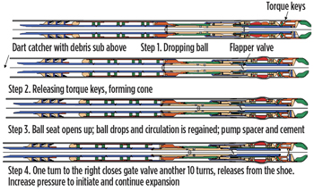
The solid expandable casing was made up and run to the setting depth with no issues through the casing exit and underreamed open hole. The well was circulated until the mud properties were optimum for the cementing job. The cement unit was rigged up to pump directly through the cementing line to the cementing head. Then, the pumps and lines were pressure tested. Initially, a water spacer was pumped, followed by the cement slurry. The dart was released and displaced with lubricating mud.
The drillpipe was slacked off and 10 right hand turns closed the float valve and released the expansion tool BHA from the expandable liner. The string was picked up to ensure that it was free from the liner and 1 ft of travel was observed before the cone contacted the unexpanded liner, demonstrating that the string had been successfully disconnected from the expandable liner.
The pressure was increased and the first single joint was expanded. The cementing head was then broken out and laid down. The drillpipe was connected to the top drive and, using the rig pump, pressure was steadily increased until it stabilized and the weight displayed on the weight indicator began to drop off, indicating the start of expansion. Expansion continued systematically using the rig’s mud pump in this manner, fully expanding the liner through the window until the cone expanded the system’s anchor joint (the expandable liner hanger) affixed with HNBR elastomer bands at the top of expandable liner system. Through the expanding of the anchor joint and its elastomers, the expanded liner was secured and sealed to the 7-in. casing. The complete installation sequence is shown in Fig. 6.
|
|
| Fig. 6. Running sequence of expandable openhole liner system. |
|
CONCLUSIONS
Casing exit operations are no longer considered a limiting factor when considering the use of solid expandable systems or when looking at tortuous well-path trajectories. Systems are now available that can minimize the forces and stresses of a drillstring across the casing exit window and are also suitable in both high-side and low-side casing exit configurations. As a result, a wellbore trajectory no longer needs to be modified due to the presence of a casing exit, but instead, can utilize the most optimum path for drilling with only minimal regard to the presence of the casing exit.
Although the presence of this latest generation of whipstocks is well suited to meet the demands of today’s drilling technologies, it is proper planning is necessary and compatibility must be ensured between the various drilling and milling components. Even though casing milling and openhole drilling both rely on rotational forces and weights on bits, the values and techniques required for these operations can vary substantially between operating companies and service providers.
The ability to plan, develop, communicate efficiently with all the participants in the operation, and ultimately execute decisions at critical times is what makes the job a success, especially when well conditions are unfavorable and installation of the solid expandable casing is difficult. There is no time to stop and call for advice when issues such as ultimate limit on tension, compression, or torque are an issue. Even when all plans have been developed, the ability to make immediate decisions at the rig floor level of operations is an absolute requirement. The competency of the personnel responsible for the solid expandable casing installation is of paramount importance. The effective understanding and use of these established procedures is the only way to manage sustained performance and improve job efficiency. 
LITERATURE CITED
1. Al-Umran, M., K. Al-Amri, I. Ahmed, M. Qasim, I. Al-Obaidi, S. Zhou, T. Sander, D. Stephenson and P. York, “New 5½- in. Solid Expandable Systems Provide Effective Technology for Successful Workover Project in Saudi Arabia,” paper SPE 08057 prepared for presentation at the 2008 SPE Saudi Arabia Section Technical Symposium held in Al Khobar, Saudi Arabia, May 10–12, 2008.
2. Ferhat, A., and R. Zeghouani, Sonatrach; T. Sanders, M. Saad and M. Roushdy, Weatherford Intl. “Open-Hole Solid Expandables Eliminate Slim-Hole Configuration in Integrated Solution Workover Well,” paper SPE/IADC 127792 presented at North Africa Technical Conference and Exhibition, Feb. 14-17, 2010, Cairo, Egypt.
3. Grant, Tom, “Inventive Solid Expandable Tubular Applications Capitalize on Window of Opportunity: Openhole Liner System Prevents Loss of Hole Size in Sidetracking Operations,” paper AADE-05-NTCE-19, prepared for presentation at the AADE 2005 National Technical Conference and Exhibition, Houston, Texas, April 5-7, 2005.
4. Hamoudi, B., and K. Kartobi, Sonatrach; P. Vieira, M. Saad, and F. Torres, Weatherford Int., “Drilling Hazard Mitigation Technology Enables Drilling Conventionally Undrillable Prospect,” paper SPE/IADC 148515 presented at Middle East Drilling Technology Conference and Exhibition, Oct. 24-26, 2011, Muscat, Oman.
5. Hogg, C., R. Barker, J. Penangos, R. Leon, C. Gandara, E. Prada, P. Chipatecue and H. Rueda, IADC/SPE SPE-150347-PP, “Milling Low-Side Casing Exit Windows in Horizontal Wells: A Case Study,” prepared for presentation at the 2012 IADC/SPE Drilling Conference and Exhibition held in San Diego, California, March 6–8, 2012.
6. Jeffre, A., A. Dossary, S. Zhou, et al., “World’s First MRC Window Exits Out of Solid Expandable Open Hole Liner in the Shaybah Field, Saudi Arabia,” paper SPE/IADC 97514, presented at the 2005 SPE/IADC Drilling Technology Conference and Exhibition, Dubai, Sept. 12-14, 2005.
7. Ring, et al., New Level of Expandable Connector Qualification Helps Minimize Operational Risk in Solid Expandable Liners; SPE 110920, presented at 2007 Annual Technical Conference and Exhibition, Anaheim, California, USA, November 11-14, 2007.
8. Rivenbark, M. and Abouelnaaj, K.: “Solid Expandable Tubulars Facilitate Intelligent-Well Technology Application in Existing Multilateral Wells,” SPE 102934, presented at the 2006 SPE ATCE, San Antonio, Texas, 24 - 27 September.
9. Saad, M., and P. York, Weatherford Int.; A. Ferhat, Sonatrach, “Workover expansion optimizes wellbore geometry – Expanding an openhole liner to isolate a high-pressure shale zone preserved hole size and prevented a slimhole configuration in the production zone.” World Oil, July 2010.
10. Sparling, S., and G. Noel, “Expanding Oil Field Tubulars Through a Window Demonstrates Value and Provides New Well Construction Option,” paper OTC 16664, Offshore Technology Conference, Houston, Texas, May 3-6, 2004.
11. Umran, M., I. Obaidi and S. Zhou, et al., “Solid Expandable Tubular Technology Applications in Saudi Arabia: Lessons Learned,” IADC/SPE 111871, presented at the 2008 IADC/SPE Drilling Conference, Orlando, Florida, March 4 - 6, 2008.
12. Waddell, K., and R. Schuumans, “Installation of Solid Expandable Tubular Systems Through Milled Casing Windows,” paper IADC/SPE 87208, IADC/SPE Drilling Conference, Dallas, Texas, March 2-4, 2004.
13. Zhou, S., O. Faraj, and R. Morris, et al., “Saudi Aramco Lessons Learned from Expandable Tubular Applications,” paper presented at the 2004 SPE Applied Technology Workshop on Expandable Technology, Phuket, Thailand, July 22-25, 2005.
|
The authors
|
|
TOM SANDERS is Regional Operations Manager for Solid Expandables at Weatherford International. Mr. Sanders has more than 35 years of experience and has been involved with solid expandable tubular since 2001.
|
|
|
PAT YORK is currently the Global Director with the Well Engineering & Project Management for Weatherford International. A 40-year industry veteran, Mr. York has been involved with solid expandable technology since its global implementation at Weatherford in 1998. He received his B.S. in electrical engineering at Northwestern State University in 1972.
|
|
|
CLIFF HOGG is the ReEntry Systems Global Product Line Manager for Weatherford International and is currently based in Houston, Texas. Mr. Hogg has served as the program developer and instructor for the SPE Multilaterals short course. Hogg is a 1987 graduate of Texas A&M University with a degree in petroleum engineering.
|
|
|
FRANZ TOMPEK is currently a Field Service Specialist at Weatherford. He was hired by Weatherford Saudi Arabia Ltd. in 1981 as a service technician and has gained experience in multiple areas. Tompek worked with groups ranging from, Weatherford Oil Tool BmbH in Algeria as a foreman in the Fishing Department to his current position with Multilaterals and Casing Exit services.
|
|
|
ALI FERHAT is Sonatrach’s Division Production Operation Director for the Hassi Messaoud Field. Mr. Ferhat has more than 29 years of experience in the oil industry in a variety of sectors including workover operations, production operations, and drilling. Mr. Ferhat has co-authored several technical publications on the application of solid expandable casing for the Sonatrach operations.
|
|


