Successful qualification and deployment of a High-Pressure
|
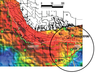
MATHIEW CAMUS, PASCAL AUCLAIR, Total E&P Nigeria Limited; BARRIE HORSBURGH, Cameron; YANN GALLOIS, CHRISTOPHE ROHART, JIM MILLER and YANNICK MFOULOU, Vam Drilling A High-Pressure Drill Pipe Riser product for Intervention Systems (DPRIS ), designed and qualified for the Usan Project in Nigeria, was manufactured in 2009, extensively tested and qualified prior to delivery the same year. The qualification performed included the ISO standard requirements and additional testing as requested by the Cameron/TOTAL Usan project team. This workstring has been successfully deployed since July 2010 offshore Nigeria by TOTAL. In February 2008, Total was given approval from the Nigerian government to begin the development of its offshore Usan field. Discovered in 2002, Usan lies in license block OPL 222, around 100 km south of Port Harcourt, in water depths ranging from 750 m to 850 m. Proven and probable reserves of Usan were estimated at 500 million barrels of oil. Usan is expected to come onstream in 2012 and to ramp up quickly to a plateau production of 180,00 bpd of oil. The associated gas will be reinjected in the reservoir. After a brief description of the needs expressed by the Operator and the operating conditions dictated by the Usan environment, the paper details the various options that were available to TOTAL for the setting and maintenance of its subsea installations. Then it highlights the benefits of using a DPRIS among available options. The pipe delivered as part of this project are drill pipe risers with a propriety double shoulder connection and featuring a gas-tight metal-to-metal seal on the inner shoulder. DPRIS use has greatly expanded from the initial two South American systems to more than 50 DPR systems presently operating in deepwater offshore regions. Their use is, however, fairly new to the African deepwater market. To mitigate the risks associated with the introduction of new technology, an extensive qualification program was conducted that covered fatigue resistance, gas tightness, tensile loadings, temperature cycling and run-ability (stabbing, round-robin make and break, tripping time) as a minimum. The qualification program additionally covered all remaining requirements for full compliance to ISO-13628-7, which is believed to be a good certification level for such demanding and challenging operations. As a conclusion, this article draws a short summary of the first operations using the system offshore Nigeria. Feedback on the preparation phase and the first deployment is also given. It draws lessons from the implementation process created, which is believed to be of technical and commercial value in the deepwater intervention business in Africa and throughout the world. Project context The Usan field lies offshore Nigeria in Block OML 138, about 100 km south of the Nigerian coastline, Fig. 1. Water depth ranges from 660 to 820 m. Field owners include EPNL – TOTAL, the operator; and Chevron, Esso and EPNL-NEXEN. Subsea facilities are arranged around a FPSO and composed of 23 production wells, 10 gas injection wells and nine water injection wells. There is a potential for up to 32 production wells, bringing total well count to 42 bores. Each of these will be fitted with a subsea tree, installed at the seabed.
Drivers for DPRIS selection Before DPRIS, most operators used conventional drill pipe available on rigs to install and retrieve the production adapter base and tree cap. These were simple, open water operations that did not require annulus control, pressure containment or fluids circulation. Occasionally, companies used drill pipe as a work-string in tubing hanger retrieval operations. Pipe could be deployed with a hydraulic jar to unstick tubing hangers. While success varied, the difficulties and risks of using a hydraulic umbilical inside the riser were clearly identified and made it evident that technological improvement was needed to minimize interference between the pipe and the hydraulic lines. Existing designs for dual vertical-bore risers were adequate for shallow water completions, but as time passed and subsea completions moved to increasingly deeper water, risers became a more costly and less desirable solution. Today, drill pipe risers serve as running string for the installation and retrieval of subsea trees and tubing hangers, as they provide an improved flow-path for annulus access of circulation and are fully NACE compliant for the most extreme sour service environments. They also provide conduit to the surface vessel for well production testing and wireline or coiled tubing services and can be run in open sea mode and inside drilling riser and BOP systems. Five of the key end user’s drivers used for DPRIS selection in the Usan field were:
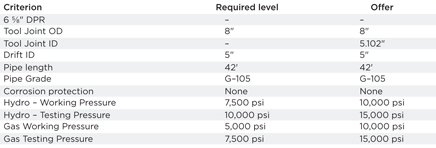
These fiver drivers were linked to company policy as well as specific project parameters, Table. 1.
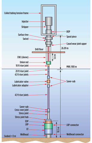
High-Pressure DPR design A typical Xmas tree, Fig. 3, is an assembly of valves, spools, and fittings used in wells. The valve at the top is called the swab valve and lies in the path used for well interventions like wireline and coiled tubing. For such operations, a lubricator is rigged up onto the top of the tree and the wire or coil is lowered through the lubricator, past the swab valve and into the well. This valve is typically manually operated. The saver sub is a short length of drill collar that has male threads on one end and female on the other. It is screwed onto the bottom of drillstring and the stress joint. This adds an additional buffer protecting the downhole assembly. The Stress Joint acts as a buffer between the stress of the riser string and the downhole assembly. The Emergency Disconnect Package (EDP) is designed for an emergency allowing the completion/intervention vessel to disconnect from the subsea well while under load with a high disconnection angle. The EDP disconnects from the LRP and isolates the riser from the environment. A production retainer valve shuts in the riser and the annulus master valve shuts in the riser. A crossover valve allows circulation of the riser after disconnection. The Lower Riser Package (LRP) is designed to isolate the well from the personnel and the riser. The Pipe Slip Ram (PSR) hangs off the work string and provides the means for retrieval of a sheared work string once the emergency has ended. The Lower Blind Shear Ram (LBSR) shears the work string and provides the primary seal to the environment. The Upper Blind Shear Ram (UBSR) shears the work string and provides a secondary seal to the environment. The advantage of the DPR system is that a conduit is created that allows the circulation of fluids (production testing), as well as wireline and coiled tubing services. The Xmas trees were installed using the conventional drill pipe system available on the platform. Dual vertical-bore risers (OCTG products for example) were used for the circulation of fluids, however this is extremely expensive when doing workovers. A 65/8-in. OD drill pipe was selected to meet the minimum drift requirement. Although this dimension has become an industry standard for DPR systems, the considerations for pipe design included:
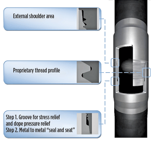
This study highlighted that the standard offer for high- pressure DPR, being with 65/8-in. 0.5-in. wt and X-95 grade, did not provide sufficient safety margin when considering the worst operational conditions with the assumed 3 mm corrosion/wall thickness tolerance allowances. The minimum wall thickness requirements for the standard pipe joint are calculated to resist loading due to internal pressure, external pressure and combined loading effects between tension, bending and external pressure. All dimensions were chosen in accordance with API RP 2RD for all operating conditions, including pressure test operations. The different criteria evaluated as failure mechanisms during operation were in-service - burst, in-service - collapse, in-service - buckling and hydrotest - burst. Note that when considering burst analysis, API 2RD provides the formula for calculating the Von Mises stress, which depends on the radial, hoop and axial stress. For a pipe, the upper region of the riser assembly experiences high tensile stresses due to high tension loads caused by the lower assembly. The lower region experiences high radial and hoop stresses due to the hydrostatic pressure in and out of the riser system. Thus, burst analysis must be performed at all locations throughout the riser assembly. For the riser pipe material, 105 ksi yield strength steel was assumed. The maximum internal pressure considered in the open water mode is the design pressure of 5,000 psi. The riser tension is calculated assuming 50Te tension at the top of the EDP. Performance levels of other product lines, as well as improvements on the processes within manufacturing, were combined to give birth to a new DPR offer. The option, with thicker wall for corrosion allowance and higher grade for tensile strength, (65/8-in. 0.625-in. wt and G-105 grade) was offered and accepted. Also at this stage it was evident that the connection’s mechanical resistance associated with this new pipe had to be improved when upgrading the forging properties from 110 ksi to 120 ksi minimum yield strength. The nominal wall thickness of the standard joint supplied is 0.625 in. An allowance of 3 mm is assumed in the calculation to account for the material loss at any point on the riser. This assumption accounts for a reduction of wall thickness due to external corrosion and wall thickness tolerance. This material loss is assumed to be uniform and to occur on the entire pipe wall. The dominating condition is burst at the surface due to design pressure and tension. The critical wall thickness requirement is found in the marine riser mode, where a nominal wall thickness of at least 0.51-in. – including corrosion allowance – is required for the standard pipe joint. With the designed nominal wall thickness, calculated maximum bending in open water mode with the 5,000 psi design pressure and 50 Te base tension was evaluated at 450,184 lbs-ft. Run of the Tubing Hanger (TH) and Upper Completion (UC) The run is performed inside the marine riser, after the lower completion has been installed. The UC is terminated with the TH, which is connected to the landing string. The WOR 6/58 VAM DPR are then doing the link between the landing string and the suface. Connection design The gas-tight seal in the first-generation DPR connection is achieved with a Teflon seal ring close to the external shoulder. The metal-to-metal seal of the second- generation DPR is located close to the internal shoulder of the tool joint. This design solution allows for reduced contact pressure on the sealing surface, giving better stability to the seal contact and has the added benefit of effectively reducing the possibility of early galling. Furthermore, due to the position of this seal, gas pressure migration from the Internal Diameter (ID) into the connection is avoided. To achieve the stable behavior of the metal-to-metal seal for the range of possible interferences due to production tolerances, the design has incorporated a double radii, or wave effect, in the 1/4-in. taper seal area. With two contact surfaces, the solution offers better contact pressure distribution and reduces the risk of galling without reducing the performance of the seal. In addition, the fact of having the seal close to the internal shoulder benefits the connection design as it provides consistent and stable contact pressure under combined loads. Design improvements on the second-generation DPR included a proprietary thread profile. This modified API thread form features a reduced angle on the loading flank to reduce the sensitivity of the connection to high axial tension. It also provides better control of the sealing zone. Other changes include a larger pitch diameter to achieve a better balance between pin and box critical cross sections, and a reduction of the threads per inch to guarantee quicker make-up. The thread root radius has been increased to provide better fatigue resistance. A stress relief groove was added on the box to avoid dope pressure entrapment for better fatigue behavior. These improvements enhance the performance and efficiency of the connection, increase service life and help reduce non-productive time on the rig floor. All of these specific features were further engineered via finite element analysis (FEA).
Qualification program By calculation and finite element analysis it was demonstrated that the majority of the qualification test results for 110 ksi connections was transposable to 120 ksi connections. Thus a reduced test plan was agreed upon between the field user and the product manufacturer to validate the new 120 ksi configuration according to ISO13628-7:2005 in consideration of the Usan field loadings. Transposable results included connection robustness to 100 make & breaks (M&B) already validated on seven samples; connection robustness to round-robin test validated on three connections; combined load tests validated on three connections at 15,000 psi and 1,000 kips; external pressure water leak tightness validated on three connections at 10,000 psi; and connection burst test without leak until 30,000 psi internal water pressure. New validation tests that were agreed upon included resonant fatigue test with mean tension applied by 5,000 psi internal water pressure; temperature cycles tests between 121°C and -18°C; low-pressure test before and after temperature cycling; and third-party witness of all tests and approval on qualification documentation. Fatigue tests with mean tension
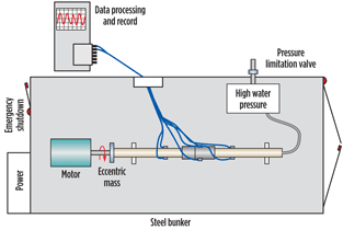
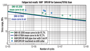
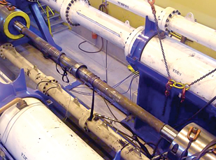
All samples for Usan DPRIS qualification were extracted from actual production. The connection had standard machining tolerances and the material, the surface treatment and the welding process were fully representative of the delivered drill pipe risers. Fatigue samples were cut at length, and end caps were welded at both ends. Pin and box were made up in a manner to have the tool joint as centered as possible in the the resonant fatigue frame. The tool joint alignment in the middle of the sample is strategic to generate a symmetrical bending moment along the sample and to avoid creating artificial overloading on one side. Hydraulic proof test was performed on each sample before fatigue testing to confirm assembly integrity. As recommended by the ISO standard, a pressure of 7,500 psi representing 1.5 times working pressure is applied during three minutes and then 15 minutes. No leak was observed. A quantity of three DPRIS has been submitted to resonant fatigue at three different stress levels and with 5,000 psi internal water pressure. The test was continued until a pressure drop of 250 psi was detected. All fatigue failures were detected due to leaks caused by cracks as shown in Fig. 7.
All failures occurred in the pipe upset zone and after a longer cyclic time than the minimum specified. The upset zone is known as a weak part of drill pipe in terms of fatigue and is the location where maximum bending stress is measured during a resonant fatigue test. These results were therefore conclusive. A fourth DPRIS was submitted to 500,000 fatigue cycles, then submitted to 80% pipe body yield strength in tension at low internal pressure. No leak was detected, and thus the sample was continued in resonant fatigue until failure.
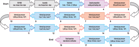
Temperature cycling with pressure cycling test ISO 13628-7:2005 refers to ISO 10423:2003 F.1.11 defined by the test protocol conducted for pressure and temperature cycles. The field user needed a qualification of the connection to temperature class U (i.e., between 121°C and -18°C). Opportunities were identified in some workover operations with nitrogen injection by coil tubing inside the riser string for low temperatures at the connection level. A DPRIS from production with standard dimensions, standard surface finish and friction welded using standard processes was prepared with proprietary end fixings. This connection was first subjected to a series of 100 make & breaks (M&B). The connection was inspected and fresh dope reapplied every two M&B. No galling was observed during or after the 100 M&B. A leak path was cut on the external and internal torque shoulders in a manner to ensure that the metal-to-metal gas-tight seal was the only effective seal during the test. Then the hydraulic proof test was conducted in the same manner as for other fatigue samples. An assembly of cooling copper coil, temperature insulation covers and heating coil was fitted around the sample before placing it in the 1,350-ton static test frame. Internal gas pressure was applied using a mixture of 90% nitrogen and 10% helium. The leak detection was achieved via a helium spectrometer calibrated to identify a leak of 10-4 N.cm3/s (equivalent to 0.36 N. cm3/hour or 0.9 cm3/15 min). To validate the functionality of the detector during the test, a measure of the quantity of helium in the air was performed at the beginning and the end of the test. The level measured needed to fall between 3.10-6 and 7.10-6 N.cm3/s. During the full test the temperature did not exceed limits by more than 11°C, and the pressure remained stable above 5,000 psi and with variation under 250 psi per hour during the one-hour qualification process as required by the ISO standard. The testing flow chart is detailed in Fig. 12 below.
The DPRIS solution delivered to the Usan field successfully passed the fatigue, wearing and temperature cycling tests as requested in addition to the existing qualification data. Final factory acceptance tests were conducted on 100% of the production pipe with internal water pressure at 7,500 psi; 10% of the production pipe was tested with internal water at 10,000 psi, followed by internal gas pressure at 5,000 psi. All pipe and connections remained tight and were accepted for Usan operations. Operations Since July 2010, the string has been in use offshore Nigeria. A total of 20 runs have been performed with this DPRIS. Of the 20 runs, 12 were performed inside riser, and eight in open hole for the successful installation and testing of four Christmas trees. Only the first set of tools has been used for these operations. Of these, there have been no cleaning issues and no rust debris impacting operations. Generally, the torque and connection make up and running at the rig presented no significant problems. One joint was eventually damaged due to over-torque at the rig floor. It was removed and operations proceeded seamlessly. Finally, the end user reported no NPT related to this DPR system to date. The run was performed in open water, and the operation took place after the upper completion was successfully installed in the well. The Xmas tree was staked up with the open water landing string (OWLS) composed of the EDP and LRP. It was run in water in the vicinity of the well using the workover riser (WOR) DPR. At surface, the last joint of WOR was connected to the surface equipment: basically a flow tree, a coil tubing frame and a cased wear joint. Once the tree is at depth, the rig navigates to the well. Using the drill pipe system, the tree is aligned with the wellhead (the entire boat is moved around to achieve alignment). The tree is then landed by lowering the entire system. Once landed, the tree is locked in place and tested. Then the well, which is produced through the VAM DPR based WOR, is tested. The weight of the assembly suspended on the WOR is around 100 tons, and the well is flown directly in the WOR, at this stage the pipes are the only barrier between the live well and environment. Specific stress joints take the bending effort during the operation and the gas proportion is quite low. Lessons learned As it appears, long-term planning has proven key to the successful qualification of these DPRIS. Although it is too early to call the deployment a complete success, the smoothness of the operations thus far provides confidence in future DPRIS runs. This DPRIS is being run better (smoother, quicker, safer) than previously on the African shelf. The solution provides efficiency and reliability in the region and throughout the world it is important to highlight the good communication practices established before, during and after deployment of the solution. Training and technical documentation has been provided in advance to field users to ensure proper utilization of the products offshore. Proper operating procedures implemented by field personnel have allowed for safe and efficient subsea runs. Beyond manufacturing and R&D, the inspection, repair and maintenance must also be planned. This network is essential when deploying the DPRIS solution. Regular inspections must be carried out at the rig site by the field running personnel, and a visual inspection of pipe and threads must be performed after each run. Runs can last between 2 and 33 days in this field. The rig inventory is replaced once a year and sent onshore, where a full inspection is carried out on internal and external parts of the pipe and threads. Defects on the OD and wall thickness are also inspected. Should repair be required, a nearby workshop has been qualified to recut the connection. There are 38 more Christmas trees to be landed. It will therefore be crucial to maintain these good practices for safe, reliable and successful operations. Acknowledgements References and Abbreviations
|
|||||||||||||||||||||||||||||||||||||||||||||||||||||||||||||

