Once the final casing string has been set and cemented in a highly deviated, horizontal wellbore, the subsequent completion step is often complicated and costly. Because the producing formation is located in the horizontal section of the well, the ability to deploy perforating guns via conventional wireline will be severely limited, as gravity cannot play a role in moving the guns to target depth.
Circumventing this challenge has often meant conveying the perforating guns by running coiled tubing, jointed pipe or drill pipe, or through the use of a tractor device to pull the guns into the well. These procedures typically require a very clean casing interior to ensure efficient deployment and may include the following sequence of operations:
• Moving the drilling rig and associated equipment off location while waiting on cement, or retaining them to perform cleanout and subsequent completion operations
• Mobilizing and rigging up a lighter-duty workover unit or a coiled tubing unit to perform the cleanout
• Deploying drill pipe- or tubing-conveyed perforating guns
• Moving the workover unit off location to allow rig-up of equipment for fracturing operations
• Finally, completing the well, which may or may not require the running of additional tubulars with a workover unit.
Not only is this sequence time consuming, but it adds several additional costs to the completion of a well in the form of a required round trip to clean up the casing after cementing, the need for tubing-conveyed perforating guns and their associated transportation regulations, and the increased incidence of nonproductive time (NPT).
For one operator completing a well in the Barnett shale, concerns about cement quality and the need to avoid coiled tubing units and cleanout runs led to a search for an alternative means of cement cleanout and perforating gun deployment. The operator, Quicksilver Resources, selected a novel completion system involving latch-in plugs that rupture at predetermined pressures to allow fluid to pass through. Because displacement fluid can exit the wellbore into the formation through the ruptured cement plug after the casing is cemented into place, the displacement fluid itself can be used to convey the perforating guns into the horizontal section of the well. This method provided Quicksilver with considerable cost savings by avoiding the need for a coiled tubing unit and associated equipment and personnel.
SYSTEM DESIGN
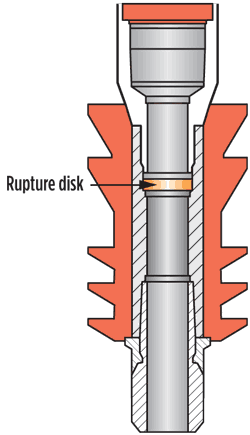
The main component of the completion system is a specially designed cement wiper plug containing a high-pressure rupture disk, Fig. 1. The system incorporates a modular design that allows for deployment in single-, dual- or triple-plug configuration, and in sizes ranging from 3½ in. to 5½ in. The field-adjustable rupture disk provides flexibility for high- and low-pressure applications. The plugs are equipped with polyurethane fins that provide enhanced wiping capabilities and abrasion resistance to produce a clean casing ID, thus avoiding the need for a cleanup run.
 |
| Fig. 1. Latch-in, high-pressure rupture plug. |
|
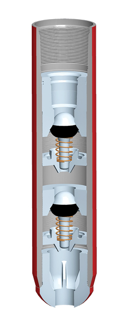
The plug (in multiple-plug configurations, the bottom plug) lands into a dual-valve float shoe (Fig. 2) that is incorporated into the casing string at the toe of the well. It latches into the float shoe via a retaining mechanism, providing redundant backpressure capability. The float shoe uses two high-strength, spring-loaded plunger valves that have been tested to a 24-hr flowrate of 10 bbl/min. and to 10,000 psi of backpressure at 300°F. The double-valve design uses fluid hydraulics to draw the plunger firmly into the retainer cup, which minimizes fatigue and reduces plunger contact with the sidewall. As a result, erosion damage to the plug from high-velocity flow during fluid or cement displacement is minimized. The float shoe provides a readily detectable high-pressure bump (to determine when the plug has landed) and a means of testing the casing.
 |
| Fig. 2. Dual-valve float shoe. |
|
Because they are modular, the plugs can be joined together to provide a greater plug length or to enable the use of multiple plugs should separation of displacement fluid or spacers be deemed necessary. In addition, each plug has an anti-rotational feature, an important rig-time saver in the event that drill-out of the PDC-drillable plugs and float shoe is required.
Procedure. The system provides an alternative method of cementing the casing and of deploying wireline perforating equipment. After the final casing string is installed, the cement is displaced using a high-pressure rupture plug followed by a calculated amount of retarded water.
After the plug is bumped and latched into the float shoe, a casing pressure test is performed, and the plug is then ruptured by increasing the pressure. The field-adjustable rupture disk ruptures without damaging the float valves. This allows the retarded water to be placed around the shoe, displacing the cement into the annulus and providing access to the formation below. Because of the plug’s wiping properties, a well cleanup run is not required. The drilling rig can then be moved off location while waiting on cement, providing cost savings.
A wireline perforating unit and fracturing equipment are then mobilized to the wellsite and rigged in to complete the well, and injection rates are established through the shoe. Wireline perforating guns are then pumped into the well, with an optional wireline-set bridge plug attached below the guns, if desired, and perforation is carried out as required. In 5½-in. casing, standard 4½-in. guns can generally be run in without adjustment; there is so little clearance between the guns and the casing wall that the fluid rate will push them all the way to the toe. For smaller guns with specially designed charges, a rubber pump-in sub can be added to increase the OD of the guns. Upon wireline retrieval of the perforating guns, the fracturing job can then commence immediately.
This approach eliminates several contributors to NPT, reduces the cost of perforating and fracturing, and speeds up the overall operation.
Multiple cementing scenarios. Depending on the well and the requirements for its completion, the high-pressure rupture plug can be used in three distinct configurations to cement the final casing string in place and provide for the use of wireline perforating methods.
A one-plug system is typically used in shallow wells with short laterals—a situation in which a high-pressure casing test upon completion of the cement displacement is normally not required. In this application, the plug is pumped in behind the cement, followed by the calculated amount of retarded water necessary to displace the cement past the shoe by some predetermined amount. Displacement fluid is then pumped. The plug is bumped, pressure is applied to rupture the disk, and then the cement is displaced by a precalculated volume to achieve the required placement of the retarded water.
A two-plug system can be deployed in applications where it is essential to have a well-consolidated cement job in the annulus that is free of contamination. In this case, the first plug is pumped ahead of the cement to prevent any contamination of the cement during displacement. The cement is followed by the second plug and then the calculated amount of retarded water and displacement fluid, as needed. The first plug is bumped, latched into place and ruptured. The cement is then pumped around the shoe, the second plug is bumped and latched in, and the required pressure test is applied. The pressure is then raised to rupture the upper plug and allow the required displacement of cement past the shoe into the annulus above.
In deeper, longer laterals where a casing test is required with an exact measured volume of cement in the annulus, a three-plug system is generally applied. The first plug, equipped with a low-pressure rupture disk, is run ahead of the cement to prevent contamination while being displaced through the casing. The second plug is then run behind the cement, equipped with a medium-pressure rupture disk, and is followed by the calculated amount of retarded water. Finally the third plug, which is fitted with a high-pressure rupture disk, is pumped behind the retardant, followed by displacement fluid as needed.
The first plug is bumped, latched and ruptured, allowing the cement to be displaced into the annulus. The second plug is then bumped, latched and ruptured to allow displacement past the shoe. Finally, the third plug is bumped and latched, at which point a casing pressure test is performed. Its subsequent rupture provides access to the formation below the shoe. The use of three plugs in these longer and deeper laterals means that the casing is wiped clean of cement twice, Fig. 3.
 |
| Fig. 3. Sequence of events for deploying a three-rupture-plug system. |
|
FIELD APPLICATION
This approach to cementing and facilitating wireline perforation has been successfully run in many shale applications in Texas, Oklahoma, northern Louisiana and eastern New Mexico over the past four years. In one Barnett shale operation for Quicksilver Resources, concerns about cement quality behind the casing and the need to avoid coiled tubing units and cleanout runs on a 5,500-ft lateral prompted the running of a three-plug system.
The standard process for deploying the three-plug system was applied, in which the first plug was deployed ahead of the cement to prevent contamination. The cement job was run without issue, followed by a plug with a lower-pressure disk to isolate the retarded water from the cement and, finally, a high-pressure plug to allow for testing of the casing and isolation of the retarded water from the displacement fluid.
The first plug was bumped, latched in and had its disk ruptured as planned, followed by the second plug, which was also latched in and ruptured at the anticipated pressure. This action forced the retarded water out into the annulus, and in the process removed all the cement from the float equipment and left retarded water around the shoe track. The uppermost plug was landed and latched as anticipated, and pressure was increased on the disk to about 4,500 psi to test the casing, after which the casing pressure was bled off.
Once the operator was ready to complete the well, a high-pressure pump truck and wireline unit were rigged up, and the top plug disk was ruptured at a pressure of about 6,800 psi. The operator then established a 7–8-bbl/min. pump rate into the formation through the plugs and shoe. Next, the operator rigged up wireline, and pumped down a plug and the first set of perforating guns with a bridge plug below. The assembly was pumped all the way to the toe, the bridge plug was set, and the wireline guns were then pulled up to the desired perforating depth. The casing was perforated, and the wireline guns were pulled out of hole, at which point the well was ready for the frac team to begin its hydraulic stimulation operation.
This application avoided the need for a coiled tubing unit and all the ancillary equipment and resources, including a bottomhole assembly with a motor, bit and disconnect; a dedicated field engineer to run the equipment; and a high-pressure pump truck for breakdown. As a result, the new application method saved the operator more than $50,000 on this one completion alone.
Table 1 summarizes the other applications in which the high-pressure rupture-plug system has been run. While the actual savings per well varies by completion procedures, this method of pump-down wireline perforating has demonstrated savings of about $45,000–$65,000 per well. These savings estimates are based on the costs of mobilizing tubing-conveyed perforating guns and deploying the guns into the well by jointed tubing, coiled tubing, drill pipe or well tractors.
| Table 1. Application history summary for rupture-plug system. |
 |
CONCLUSIONS
This procedure has been successfully used in more than 500 separate applications since its inception. The rupture-plug cementing system has allowed operators to realize several improvements while deploying perforating devices:
• Eliminating a casing wiper trip after cementing provides cost savings by allowing the drilling rig to be released.
• The need for a workover or coiled tubing unit is eliminated.
• Overall costs are reduced by facilitating the use of wireline perforating equipment because of the elimination of equipment and logistical costs associated with tubing-conveyed perforating.
• An overall reduction in NPT is achieved by the reduction in frequency of surface equipment change-outs.
Other completions systems exist that allow for fluid to pass through the toe of the well after cementing, such as sliding-sleeve and drop-ball methods. These methods would also allow for pump-down deployment of perforating guns, but unlike the rupture-plug system, they cannot clean the casing interior. They are also much more expensive than the rupture-plug system.
To complete the well following fracturing operations, a coiled tubing unit or workover rig is still required to drill out the plugs and clean up the well. However, the overall time that one of these units is needed to complete the well is greatly reduced using the rupture-plug method, resulting in substantial cost savings. 
ACKNOWLEDGEMENTS
This article was prepared in part from SPE/IADC 140304 presented at the SPE/IADC Drilling Conference and Exhibition held in Amsterdam, the Netherlands, March 1–3, 2011.
THE AUTHORS
|
|
 RYAN HORD is a Drilling Engineer with Quicksilver Resources, assigned to horizontal drilling projects in the Fort Worth basin. He holds a petroleum engineering degree from Texas A&M University. RYAN HORD is a Drilling Engineer with Quicksilver Resources, assigned to horizontal drilling projects in the Fort Worth basin. He holds a petroleum engineering degree from Texas A&M University.
|
|
|
THAD SCOTT is Weatherford International’s Global Product Line Manager for Cementing Products. Since he joined the company in 1996, Mr. Scott has held positions in engineering, R&D, regional management, human resources and QHSE. He holds a BS degree in mechanical engineering from Louisiana State University and has been issued six patents.
|
|
|
FRED WEEKS brings 40 years of oilfield experience to his current role in corporate sales for Weatherford in the Barnett shale, including 25 years working with downhole cementing applications and equipment. In addition to cementing, he has worked in fracturing, casing running services, customer service, training, manufacturing and sales in regions such as the Gulf of Mexico, the Gulf Coast, Nigeria, China, South America, the Middle East, North Africa, India and Pakistan.
|
|
|
MARCEL BUDDE is R&D Engineering Manager for cementing and liner products at Weatherford, and is responsible for all engineering work related to elastomers. He joined the company in 1994. Mr. Budde has been issued two patents and has authored or coauthored two Society of Petroleum Engineers papers relating to wellbore cementing and drilling tools.
|
|
| |
|


 RYAN HORD is a Drilling Engineer with Quicksilver Resources, assigned to horizontal drilling projects in the Fort Worth basin. He holds a petroleum engineering degree from Texas A&M University.
