Adam Howard, Rockwell Automation
Recent events in the oil and gas industry have substantially increased interest in maintaining the highest standards of safety possible at all times during operations. Oil and gas producers and the operators who manage their production facilities are demanding the highest levels of safety to protect personnel, the environment and production assets while maintaining maximum uptime and minimal operational disruption.
The tensions involved in balancing these critical requirements often come to a head when an oil and gas producer needs to upgrade a facility’s safety system. As safety systems age and become outdated or obsolete, they not only increase safety risks when compared to more contemporary systems, but can also cause lost production time due to unnecessary trips or shutdowns.
Installing an upgraded safety system does not necessarily require a lengthy shutdown. With careful planning and detailed, thorough engineering, a safety system can be upgraded with minimal disruption to facility operations.
THE ROLE OF A SAFETY SYSTEM
In oil and gas production operations, the distributed control system (DCS) manages the normal operation of the plant. The function of the safety instrumented systems (SIS) is to preserve life, the environment and the equipment being monitored.
The most common types of safety systems in oil and gas production are the fire and gas (F&G) and emergency shutdown (ESD) systems. The primary objective of the F&G system is to monitor for the presence of fire through smoke, heat and flame detection, as well as for potentially dangerous levels of hydrocarbons by line-of-sight, point and acoustic gas detection methods. If any of these conditions are detected, the system implements appropriate alarm, firefighting and suppression measures in order to minimize the impact to personnel, the environment and the assets being protected.
The core objective of the ESD system is to protect people, the environment and production assets against misuse, equipment failure and catastrophic failure of the plant. When the ESD system is activated, it may require an orderly shutdown of the production process to protect personnel and the integrity of the plant.
Typically, the F&G and ESD systems are physically independent of each other and separate from the DCS.
DRIVERS FOR A SAFETY SYSTEM UPGRADE
Facility owners upgrade their safety systems for a variety of reasons ranging from equipment obsolescence to the need to take advantage of the benefits of extended or more advanced functionality. The major drivers include the following:
Prolonging field life. Many oil and gas reservoirs continue to generate viable quantities of product well beyond the intended life of the original field design. Consequently, the platform has to be upgraded—often on a rolling refurbishment basis—to accommodate these extended operations. These upgrades can also help reduce annual maintenance costs while simultaneously reducing unplanned downtime and unexpected repair costs.
Meeting new codes and standards. Currently installed safety systems were designed and built in accordance with the codes and standards in force at the time. Since then, industry requirements have changed and many legacy systems have not been upgraded to current standards and technologies. For example, while IEC-61508—the international standard for “functional safety of electrical/electronic/programmable electronic safety-related systems”—was introduced in 1999, many legacy systems have not yet been reassessed to determine if they comply with this standard.
Improving functionality. Operational requirements have changed in the last 20 years as technology has advanced to include capabilities such as remote operations, improved diagnostics and simplified interfacing between systems. For example, advanced asset management tools are available that can help gather and analyze vital data from across production facilities. While this may not be a prime driver for system upgrades, it is often a key factor in the cost-benefit analysis.
SAFETY SYSTEM OBSOLESCENCE
Every piece of equipment or system will eventually come to the end of its useful lifecycle. Based on the author’s experience, safety systems need to be upgraded some 15–20 years after initial installation. For safety systems, this need can become apparent in a number of ways:
Equipment obsolescence. Equipment often becomes obsolete when the underlying components are no longer manufactured. While “last-buy” options from manufacturers can temporarily address this, the ongoing maintenance and support of these systems will no longer be viable once the supplier support infrastructure can no longer service the equipment.
Erroneous operation. As safety system components age and fall “out of tolerance,” no longer performing within their designed parameters, part of the system could begin to operate erroneously. Since safety systems are designed to fail to a safe state, this can often result in unnecessary and costly shutdowns.
Inability to expand or enhance. Legacy systems, particularly hardwired systems, are difficult to expand, beyond small changes. Therefore, expansion to accommodate new features—such as additional subsea tiebacks, artificial lift and compression facilities—is often difficult due to physical space and system interface constraints. In addition, older systems may not meet current industry standards.
UPGRADE STRATEGIES
Implementing a safety system upgrade requires an in-depth analysis and risk assessment of the existing technology, so the operator has a solid understanding of the requirements that a new system must fulfill. A safety system upgrade should follow a systematic and well-documented process.
Establish a baseline. The first step in a safety system upgrade is to establish a clear understanding of the existing design, including the specific nature of the system’s core architecture and the functional operation. The as-built documentation status of many mature systems is poor, self-conflicting or nonexistent. As a result, engineers often need to reverse-engineer the installed system to either confirm that the existing documentation is correct or mark it up to determine how to proceed.
During this phase of the project, the safety integrity level requirements may need to be established or re-affirmed. In some instances, this may necessitate revisiting the original system design. Carrying out this assessment not only means the design of the upgraded system can be compared to current SIS standards, but also may significantly reduce the complexity of the system needed.
Once this baseline is firmly defined, you can determine which system upgrades, enhancements and improvements may be needed. While this preparatory work can take a considerable amount of effort, it is essential in helping ensure that the functionality is correct and the design is traceable.
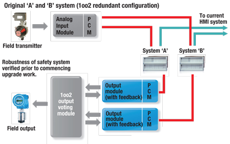
Evaluate the architecture. In order to execute a “live” migration from the legacy system to the new system, designers need to exploit the inherent redundancy built into the legacy safety system. Given that most legacy systems have an “A” and a “B” side (Fig. 1), each executing the same logic, one side can be switched off and removed without shutting down the system. It should be noted that while the system is in this degraded state, it is fully operational and, if designed that way, failsafe. However, by switching off one side, the system redundancy and fault-tolerant capabilities will no longer be available, the implications of which need to be understood through an appropriate risk review. This configuration will allow the new system to be installed and run in parallel to the legacy system, enabling a safe, quick and effective migration between the systems during live plant operations.
 |
|
Fig. 1. The original redundant safety system configuration.
|
|
Build, test and document. Once the new system is built, it is essential that it be fully tested against the defined and agreed-upon baseline before it is installed in the field. Testing the system before the live changeout in the field occurs helps to ensure that the functionality will meet the operational requirements. Any functional enhancements can only be implemented and tested after these tests are completed.
During this phase, it is also critical to get the buy-in from all interested parties, particularly the oil and gas company’s operators and the relevant certifying authority. Oil and gas producers will focus on safety concerns, the functionality of the new system, how it will be migrated and any operational constraints that will need to be addressed. The certifying authority will need to be assured that clear and demonstrable processes are in place to show that the system build, testing and—later —commissioning and operation are safe and comply with legislative and regulatory requirements, as well as local and international industry standards.
In addition to the build and test records that the system manufacturer produces, the engineering team should produce comprehensive and detailed work packs that include method statements, implementation details, reversionary plans and check sheets to verify the installation, commissioning and handover of the system. This is essential in recording, to the satisfaction of the certifying authority, the work undertaken in implementing the upgraded system.
INSTALLING AND MIGRATING TO THE NEW SYSTEM
Once the new system has been tested and shipped, it can be installed and commissioned. The following is an overview of the steps needed to migrate from the legacy system to the new system during live operations. It is at this phase of the project that the detailed planning and preparation already undertaken will prove critical to successful safety system migration.
1. Fully verify the functionality of the existing legacy system, including any standing inhibits commands or overrides retained from that system.
2. Install the new system in its final location. Once installed, carry out basic functional tests—often called “travel-well” tests—to help ensure that the system is fully operational ahead of the system migration.
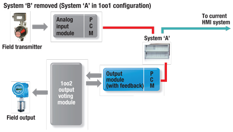
3. Remove one side of the legacy system, Fig. 2. This is one of the risk areas due to the possibility of inadvertent operation of the system, such as loose wiring disturbance. The system is now in the degraded state.
 |
|
Fig. 2. The original safety system during initial migration to the new safety system.
|
|
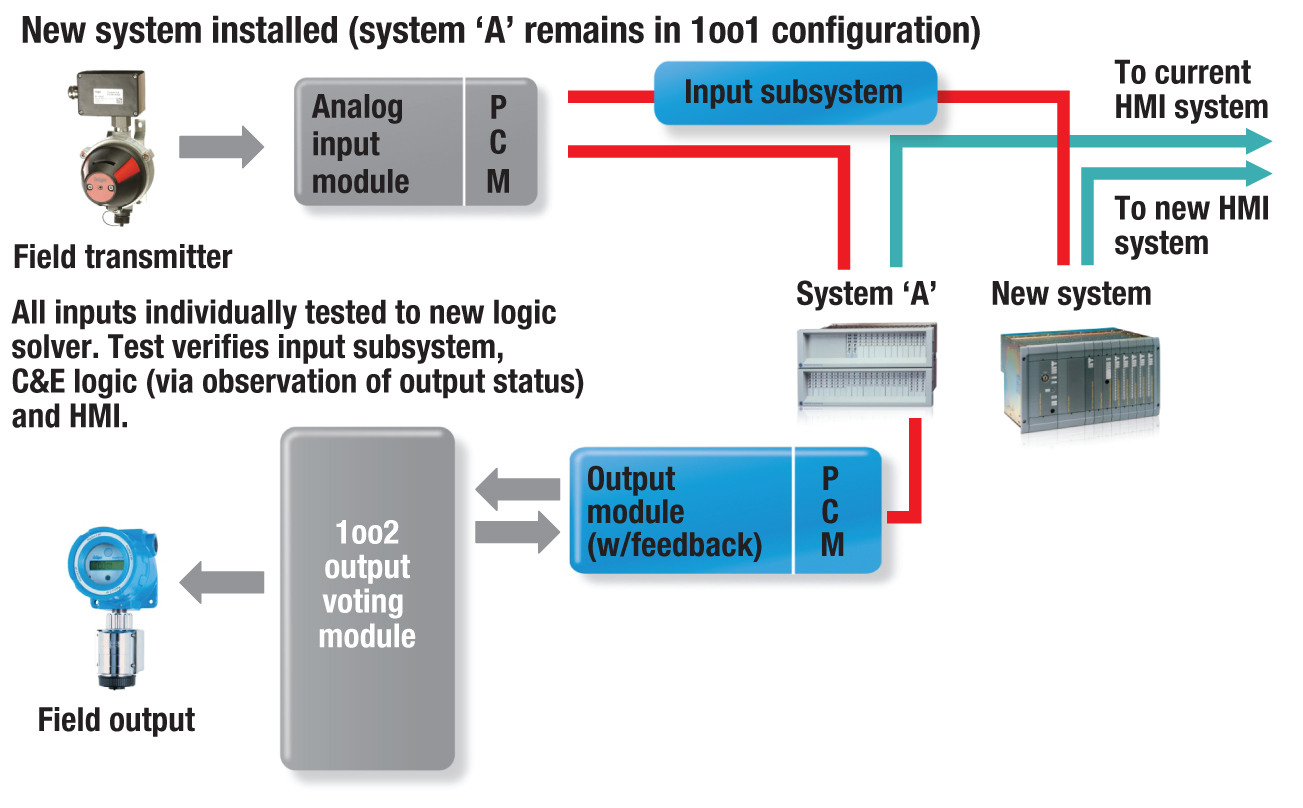
4, Hook up the field inputs, such as fire and gas detectors, to the new system, while retaining the inputs to the legacy system. The new system can now “see” the same inputs as the existing system can but, because the outputs are not hooked up, the new system is not carrying out any executive actions, Fig. 3.
 |
|
Fig. 3. Initial installation of the new safety system alongside the original safety system.
|
|
5. Fully test that both systems see all inputs and that the logic solver output actions implemented are identical to those of the legacy system. Unless otherwise specified, “like for like” functionality (meaning that both the old and new systems respond in exactly the same manner to field input conditions) is critical. This can be done by temporarily disabling the appropriate outputs, which can be time-consuming and may not be operationally acceptable, or by observation of the new logic solver against the design documentation.
6. Fully verify the human-machine interface (HMI) functionality for the new system.
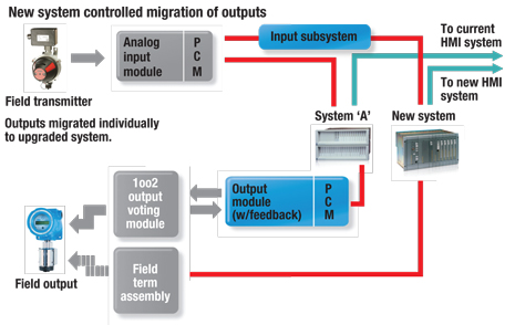
The safety system outputs can now be migrated from the legacy to the new system, Fig. 4. At this stage, the new system will assume control. This also is where the major difference between the migration of an F&G and that of an ESD system occurs. F&G outputs tend to be normally deenergized, or “energize to action,” whereas ESD outputs tend to be normally energized, and therefore “deenergize to action.” This is considered to be a failsafe design philosophy. Transferring the outputs without inadvertently tripping the plant or falsely tripping the F&G or ESD system can be challenging for system migrations of this nature.
 |
|
Fig. 4. Migration of outputs to the new safety system.
|
|
Migrating a normally deenergized output is relatively straightforward and is normally done in less than a minute per output. During this time, there is no protection for that output.
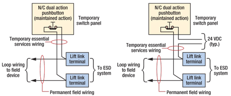
Migration of normally energized outputs present a different challenge that can be addressed either by electrically “holding up” the output using a temporary supply or by locking off the output device. This takes more planning and operational permits and is consequently more time consuming, taking typically one to two hours per output. Figure 5 shows schematically how a critical output circuit may need to be configured during an ESD system output migration.
 |
|
Fig. 5. Typical “essential services” overrides.
|
|
Once all safety system outputs have been migrated, full control of the safety functions will have passed from the legacy system to the new system.
The new system will now be subjected to full system tests. Since the facility is still live, the tests carried out may be an agreed-upon subset of the full functionality and are often guided by the requirements of the operators and the certifying authority. Any tests that cannot be carried out while the plant is live will need to be delayed until the next facility shutdown.
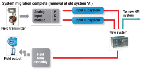
Once the upgraded system is fully operational, the legacy system can then be deconstructed. The final system, which has redundancy and fault tolerance built into its design, is shown in Fig. 6.
 |
|
Fig. 6. The new redundant safety system installed.
|
|
FINDING THE BEST APPROACH
Significant cost savings and productivity benefits can be gained from an intelligently designed and properly implemented safety system upgrade. It is important to remember that not all safety systems are created equal and that each project has different performance, risk and cost goals. Striking the right balance requires careful consideration of the specific capabilities, limitations and advantages of available technology options.
Live migration of safety systems during plant operations is possible with careful analysis of the system design and operational requirements and a thorough and detailed approach to the engineering and migration strategies. One of the best resources available is the system’s vendor. Many safety system providers can offer guidance, design recommendations and onsite assistance to help ease the migration, minimize downtime and optimize system performance.
For example, the strategy outlined in this article is based on an actual safety system upgrade of more than 3,000 input and output points on an operational production platform. The upgrade caused the end user minimal disruption to its operational requirements while providing the upgraded system needed to meet its functional safety requirements. 
|
THE AUTHORS
|
 |
Adam Howard has more than 25 years’ experience in the oil and gas, petrochemical and nuclear industries. He has worked as a Control and Safety Systems Engineer for end-user oil companies, major engineering, procurement and construction (EPC) companies and main automation contractors (MACs). Mr. Howard lives and works in Aberdeen UK, where he heads the MAC business for Rockwell Oil & Gas in Europe, the Middle East and Africa. |
|


