Uneven distribution of proppants in perf clusters
Simultaneous creation of multiple fractures through separate perforation clusters has long been a cost-effective method for stimulating vertical and horizontal wells.
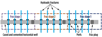
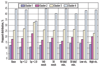
ALI DANESHY, Contributing Editor, Shale Simultaneous creation of multiple fractures through separate perforation clusters has long been a cost-effective method for stimulating vertical and horizontal wells. This limited-entry technique is based on distributing the fluid and proppant within different fractures by controlling the number of perforations in each cluster. While the limited-entry technique provides the planned fluid distribution within different fractures, the same is not true for the proppant. Numerical simulations reveal that the proppant distribution is heavily weighted toward the end clusters, with the initial clusters receiving much less proppant in comparison to their fluid share. The net effect of this behavior is uneven proppant distribution within different fractures and their uneven production contribution. By separating more fluid from the slurry, the initial perforations serve as a mechanism to increase proppant concentration within the rest of the wellbore. This mechanism is another reason why wellbore screen-outs are more frequent in horizontal wells than in vertical wells. Limited-entry horizontal fracturing. Many of the unconventional, low-permeability oil and gas reservoirs are produced by drilling long horizontal wells and creating multiple hydraulic fractures in the pay zone. To reduce the cost of fracturing, the limited- entry technique is used to create multiple fractures during each injection stage. In this process, several clusters of perforations are fractured during each injection stage, Fig. 1. Fluid injection rate is selected such that all perforation clusters are fractured during injection. Using this process, one can create many hydraulic fractures with fewer injection stages. For example, one can create 40 different fractures during 10 injection stages by placing four separate perforation clusters in each fractured interval and injecting the fluid at a sufficiently high rate to cover all perforations. The result is multiple fractures at a much lower cost. This process is commonly used in shale gas plays such as the Marcellus, Haynesville and Barnett. Limitations of limited-entry design. The fundamental assumption in the limited entry frac design is that the proppant distribution among the different perforations is the same as fluid distribution. Until now, this assumption has not been challenged or lab tested. However, there is reason to doubt that fluid and proppant will be moving together. For one thing, because of its higher density, the proppant moves with a greater momentum and consequently will have a harder time turning the corners to enter the perforations. Many fracturing fluids are also viscoelastic and generate forces normal to flow direction, which force the proppant into the middle of the slurry stream and reduce its ability to move outward toward the perforations. A series of numerical simulations were performed to explore the relative distribution of fracturing fluid and proppant while flowing through clusters of perforations. The simulations showed that, as expected, fluid distribution follows the computations and is proportioned on the basis of the number of perforations. However, proppant distribution was considerably different, Fig. 2.
In this example, four perforation clusters were created, each with four individual perforations with 0.42-in. perforation diameter. For the base case, the fluid is water and the proppant (sand) has a density of 2.65 g/cm3. The base injection rate is 60 bbl/min., together with two more rates of 30 bbl/min. and 90 bbl/min. The base viscosity is 1 cP (water) with two more values of 0.1 and 10 cP, for comparison. The data show that although there are differences for individual cases, the proppant distribution is highly distorted within the perforations, with most proppant entering the last perforation cluster. In fact, for the base case, the last cluster of four perforations receives almost four times the proppant amount in the first cluster of four. The only variable that seems to have a measureable effect on proppant distribution is proppant density, with the results getting better with lower-density proppant. This is to be expected, since the momentum difference between fluid and proppant is smaller. However, the large differences persist even for proppant that has a specific gravity of 2.0. These results show that, as speculated, the proppant distribution is very different from fluid distribution, and depends on variables such as proppant density, fluid viscosity and injection rate. The implications of this behavior are very important when trying to optimize production from unconventional shale gas and oil reservoirs. Since the production from these fractures is dependent on the amount of proppant placed inside each fracture, the aim of these multistage treatments should be to place equal amounts of proppant into various fractures. The simulations show that this objective is not being satisfied in the hydraulic fractures. As such, there is room for higher production if one can change the dynamics of proppant movement and get a better proppant distribution in these horizontal wells.
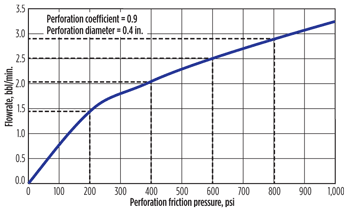
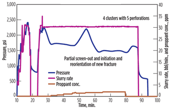
Proppant distribution is highly distorted within the perforations, with most proppant entering the last perforation cluster. The only variable that seems to have a measureable effect on proppant distribution is proppant density. However, the large differences persist even for proppant with specific gravity of 2.0.Implications for horizontal fracturing. Limited entry is a useful and cost-effective method of creating multiple fractures in a horizontal well, as evidenced by its frequent use. The exercise below is presented to enhance our understanding of the process. A common method of selecting the number of perforations is to assume a flowrate of 1.5–2 bbl/min. for each perforation. For example, to frac five intervals at 80 bbl/min., assuming 2 bbl/min. per perforation, will yield 40 perforations, or eight perforations per cluster. The computed friction pressure for this application will be about 380 psi. As perforations in a horizontal well are not likely to be equally linked to the created fracture (due to different distances from the fracture, and location around the wellbore) the actual perforation friction pressure will be higher than the ideal computation. Thus, for example, if the actual fluid pressure increases to 800 psi above the fracturing pressure, the best-connected perforation will accept fluid at a rate of 2.9 bbl/min., Fig. 3. Other perforations that experience additional friction pressures of 200 and 400 psi in the near-wellbore fracture can only admit rates of 2.05 and 1.45 bbl/min. Thus, because of the nature of their connection with the fracture, all perforations feeding the same fracture will not be taking fluid at the same rate. Although this rate difference between perforations in the same cluster also causes a difference in proppant distribution, the effect is not as large as the difference between different clusters. The actual field data occasionally shows limited screen-out during an injection period. An example of this situation is presented in Fig. 4. The pressure spike in the middle of this treatment indicates partial screen-out of some perforations. This condition reduces the effective number of perforations and causes an increase in the friction pressure of the remaining perforations—and thus at the wellbore. However, the subsequent pressure decline means breakdown of new perforations, resulting in an increase in the number of effective perforations and a decrease in their friction pressure. This data leads to an important conclusion: All perforations were not open and taking fluid at any time during the entire treatment. The occurrence of screen-out in this example may actually have helped cause the proppant to become more equally distributed among different fractures. Since perforations have an indirect effect of increasing proppant concentration, the likely location of the screen-out will be at the end perforations. Closing these perforations will move the remaining slurry toward the earlier clusters. Another point of operational importance is the use of ball sealers. These are occasionally used to seal the perforations taking higher fluid rates. However, since the density of many commercially available balls is very close to that of water, these are likely to move with the fluid and seal the early perforations. This outcome is contrary to the intended purpose and can further reduce the amount of proppant moving through the early clusters. Further lab testing. Numerical simulations confirm the theoretical expectation of unequal proppant distribution between different perforation clusters in limited-entry treatments. However, this recognition and the use of advanced numerical simulations do not lend themselves to easily applicable solutions to everyday operational issues. Establishing easy-to-use engineering relationships between the variables requires further laboratory testing of the process.
|
|||||||||||||||||||
- Prices and governmental policies combine to stymie Canadian upstream growth (February 2024)
- U.S. producing gas wells increase despite low prices (February 2024)
- U.S. drilling: More of the same expected (February 2024)
- U.S. oil and natural gas production hits record highs (February 2024)
- U.S. upstream muddles along, with an eye toward 2024 (September 2023)
- Canada's upstream soldiers on despite governmental interference (September 2023)


 ALI DANESHY is President of Daneshy Consultants International and an adjunct professor of chemical engineering at the University of Houston, where he teaches a graduate-level course on hydraulic fracturing. Dr. Daneshy provides consulting and training services on unconventional oil and gas completions using multiple fractures in horizontal wells. He has received an SPE Distinguished Service Award for his contributions to hydraulic fracturing. /
