New hydraulic lift system overcomes beam pump challenges in CBM wells
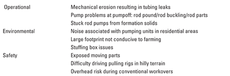
Technology incorporating a downhole diaphragm pump was found to eliminate mechanical wear and reduce maintenance, all with less noise and a smaller surface footprint than conventional lift methods in the Black Warrior Basin.Celeste Hagler, El Paso E&P Company; and Nicholas P. Boyaci, Smith Lift El Paso E&P Company operates coalbed methane (CBM) wells in Alabama’s Black Warrior Basin. Because of low reservoir pressure and low liquid rates, the majority of these wells require artificial lift to remove water from the wellbore in order to allow the coal seam to produce gas. The predominant lift method is the conventional beam pumping unit, which was first introduced in the basin around 1920. While various teams at El Paso have improved the operational efficiency of the beam pumps, the company embarked on a program in 2008 to evaluate and implement a new artificial lift technology that would address the operational, environmental and safety challenges associated with the current lift method. El Paso evaluated a number of alternative lift methods and then selected a new form of artificial lift using downhole diaphragm pumps developed by Smith Lift. A field trial demonstrated improved operational efficiency using the new design, as well as improved safety and environmental benefits. Based on lessons learned from the field trial, the operator is moving forward to deploy more diaphragm pumps in wells throughout its CBM assets. OPERATIONAL OVERVIEW The operator’s CBM wells in the Black Warrior Basin typically produce less than 100 bpd of water and 50–350 Mcfd of gas from a depth less than 2,500 ft. A typical completion uses 2⅜-in. or 2⅞-in. production tubing with a seating nipple about 30 ft below the lower perforations and about 150 ft of rat hole (the interval between the lower perforations and TD). This completion design enables the pumping system to draw the water completely off of the coal face to maximize gas rates while allowing formation solids produced with the well fluid to fall into the rat hole. Some wells are located in residential areas where safety and environmental concerns require special consideration. Other wells are located in hilly locations that present problems when trying to move larger pulling units in and out of the wellsite. The conventional beam pump is the primary artificial lift method in the Black Warrior Basin; other lift systems including progressive cavity pumps (PCPs) and electric submersible pumps (ESPs) have been used there to a lesser degree. A project was launched to improve the operational, environmental and safety aspects of the company’s artificial lift operations, by identifying challenges, evaluating lift alternatives, conducting a field trial of the selected alternative and identifying lessons learned. Frequent well reviews generated a list of recurring problems. By formalizing the project, the operator encourages field supervisors, lease operators, production engineers, electricians and service company personnel to share their experiences. Opportunities for improvement identified by personnel during the well review process are listed in Table 1.
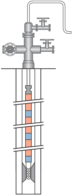
LIFT TECHNOLOGY SELECTION Other artificial lift methods already in use in the Black Warrior Basin, such as PCPs and ESPs, did not address all of the recurring challenges that were identified with conventional beam pumping in the area. Therefore, a new form of artificial lift was considered that featured downhole diaphragm technology to reduce the footprint, noise and environmental impact associated with the conventional beam pump. The Hydraulic Diaphragm Insert (HDI) pump, manufactured by Smith Lift, is designed for CBM, oil and conventional gas wells with low liquid rates at depths of less than 3,000 ft. The new pump design builds on Smith Lift’s established hydraulic diaphragm ESP technology, but eliminates the downhole electric motor and electric line to surface in order to reduce maintenance needs. Instead, an electrically powered variable-flow surface pump circulates hydraulic working fluid through one line of a twinned engineered thermoplastic hose to the downhole diaphragm pump and back through the other, Fig. 1.
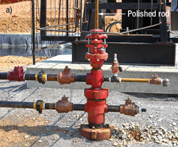
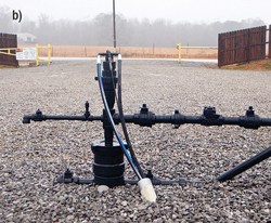
The list of recurring problems generated in the operator’s well review process was used to evaluate this new technology before embarking on a field trial test. The beam pump was used as a benchmark during the evaluation phase. Mechanical erosion. Beam pumps use mechanical energy to drive the downhole pump via a reciprocating rod string. This rod string may erode production tubing in deviated wells, causing tubing leaks. Even in supposedly “straight” holes, it is not uncommon to find localized deviations severe enough to create rod wear and tubing leaks. The new lift system eliminates the rod string and the motion that produces tubing erosion and leaks in beam pumping, because it uses hydraulic energy from the surface unit to drive the downhole pump rather than mechanical energy. Pump problems at pumpoff. A condition known as rod pound occurs when there is little or no fluid to support a downhole rod pump. The pounding action can harm the pump and cause the rod string to buckle and/or part, resulting in a costly fishing trip. In contrast, the diaphragm hydraulic system has the ability to pump off a well for a sustained period because the internal pump components are always immersed in hydraulic fluid and pump life is independent of whether there is fluid in the pumping chamber. In addition, since there are no rods, rod pound and resulting rod wear cannot occur. Stuck pumps. The rod pump depends on a tight tolerance between the plunger and barrel for good efficiency. However, when formation solids are present, either the tolerance must be relaxed, resulting in lower efficiency, or the operator must pull the pump frequently when solids interfere between the plunger and the barrel, causing the rod pump to stick. The hydraulic diaphragm method completely isolates well fluids from the internal pumping mechanism that actuates the diaphragm. The well fluid is pumped as a result of the continuous inflation and deflation of the diaphragm. Only the balls, seats and diaphragm are exposed to well fluids, thus eliminating problems associated with the plunger-to-barrel interface in a rod pump. Additionally, the hydraulic diaphragm system’s slow pump action mitigates solids production, thus reducing the frequency of wellbore cleanouts. Stuffing boxes. A beam pump uses a polished rod to connect the rod string to the surface unit, and the polished rod is partially sealed on the wellhead using a stuffing box, Fig. 2a. These stuffing boxes may leak, causing environmental damage; they also detract from location aesthetics. In the hydraulic diaphragm system, the twinned thermoplastic hose terminates at the wellhead, and surface hoses are used to connect the power unit to the wellhead. The sealed wellhead eliminates environmental hazards associated with leaking stuffing boxes, Fig. 2b. Furthermore, the system uses a benign water-based hydraulic fluid, of which about 200 gal is required for a 3,000-ft well.
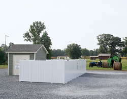
Noise. Several of the operator’s Black Warrior CBM wells are in residential areas. The noise from belts, bearings and rod pound associated with beam pumps can be a nuisance to neighbors. The hydraulic diaphragm system uses a quiet electric motor to convey hydraulic energy to a downhole pump. The low-profile surface equipment may be enclosed for additional noise suppression. Footprint. Some wells are located on farmland. The compact layout of the hydraulic diaphragm system’s surface equipment allows for a smaller well pad than that of a beam pumping unit, leaving more usable area for landowners, Fig. 3.
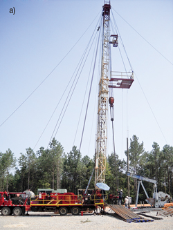
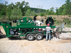
Safety issues. Several wells in the Black Warrior Basin are located in very hilly terrain. Conventional pulling rigs used to deploy beam pumping units have difficulty driving in this terrain and may require bulldozer assistance. By comparison, a truck- or trailer-mounted spooler used to deploy the downhole diaphragm pump on continuous flexible tubing is much lighter and safer to mobilize in hilly terrain, Fig. 4. The spooler also eliminates heavy objects overhead.
Another safety risk of conventional beam pumps eliminated in the new lift method is the use of belt-driven counterweights. The hydraulic diaphragm system has no exposed moving parts on the surface. FIELD TRIAL Based on the conceptual review, the operator embarked on an initial three-well field trial program in May 2008 using the new lift method. Among the wells selected for the trial, one had extremely low water production rates of less than 5 bpd; one had greater production of about 70 bwpd, near the upper limit of the hydraulic diaphragm pump’s capacity for that well’s depth; and a third well had a liquid rate between these two extremes, at about 30 bwpd. Several near-term benefits were realized during the trial period, many of which were predicted by the conceptual evaluation. These benefits included:
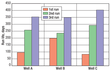
Because of the ease of deployment and retrieval, downtime due to these operations was also minimized. It was not unusual for a diaphragm pump change to take less than 3 hr for a 2,000-ft well. In addition to demonstrating the hydraulic diaphragm system’s advantages over beam pumping for this lift application, the field trial provided important information to continue evolving the new technology, resulting in increasing pump run life in all three wells, Fig. 5. After each pull, a root-cause analysis of the pump was conducted, leading to design iterations. The design continues to evolve, leading to increased run life.
CONCLUSIONS Several benefits identified during the conceptual review were realized during the initial three-well trial, leading the operator to purchase additional units to prove up the technology on a wider scale. One benefit still under evaluation is run life. Quarterly reviews are helpful to track continued progress. Current plans call for the continued use of hydraulic diaphragm technology in wells that make less than 70 bwpd in the Black Warrior Basin. In addition, the low-profile surface units will be beneficial for new drills or as replacement units in environmentally sensitive locations including residential areas and farms. ACKNOWLEDGMENT This article was prepared from “The geotechnical challenges of active geohazards in the design of deepwater facilities,” presented at the Society for Underwater Technology Annual Subsea Technical Conference held in Perth, Australia, Feb. 17–19, 2010.
|
||||||||||||||||||||||||||||||||||||||||||||||||||||||||
- Shale technology: Bayesian variable pressure decline-curve analysis for shale gas wells (March 2024)
- Prices and governmental policies combine to stymie Canadian upstream growth (February 2024)
- U.S. producing gas wells increase despite low prices (February 2024)
- U.S. drilling: More of the same expected (February 2024)
- U.S. oil and natural gas production hits record highs (February 2024)
- U.S. upstream muddles along, with an eye toward 2024 (September 2023)

